Graphical Notations for Rule Modeling
Sergey Lukichev1 Mustafa Jarrar 2 1University of Technology at Cottbus, Germany2 University of Cyprus, Cyprus
Published As: Sergey Lukichev and Mustafa Jarrar: Graphical Notations for Rule Modeling. Book chapter in "Handbook of Research on Emerging Rule-Based Languages and Technologies". Pages 76-98. IGI Global. ISBN:1-60566-402-2. (2009)
Abstract
This chapter describes various graphical notations for rule modeling. Rule modeling methodologies, empowered with graphical notations, play an important role in helping business experts and rule engineers to represent business rules formally for further deployment into a rule execution system. Rules, represented graphically, can be easier understood by business people and by technicians without intensive technical learning. In this chapter we mainly focus on three graphical notations for rules: UML/OCL, URML and ORM. UML/OCL is a mainstream modeling technology in software development, which is also accommodated by some business experts when modeling a system at the semi-formal, platform independent level. URML extends UML with additional graphical symbols and the concept of a rule, which allows visualization of different rule types on top of UML class diagrams. ORM is an alternative methodology with a rich graphical notation for modeling a domain at the conceptual level. The methodological power, graphical expressivity, and verbalization capabilities of ORM have made it the most popular language within the business rules community. This chapter introduces each of these graphical notations, explain how it can be used, and compare them against each other.
MOTIVATION
In order to deploy rules, initially communicated by business experts in natural language, into a software system, these rules have to be formalized and translated into a rule engine’s language. The process of rule translation from informal language into a technical language is usually performed by IT professionals, who might not be familiar enough with the original business domain. Therefore, the resulting rules may contain mistakes or unintended conceptions. To bridge this gap between IT and business experts, several rule modeling methodologies (empowered with graphical notations) have been proposed. The goal of such methodologies is that rules, represented graphically, can be easier understood by business people and by technicians without intensive technical learning. Through their set of well-defined graphical notations, these methodologies guide rule modelers not only on what to model, but also on validating what have been intended is exactly there.
Furthermore, while doing high-level, conceptual rule modeling and when technical details of a particular rule platform are not yet important, it is easier to work with rules, expressed graphically.
BACKGROUND
The idea of the graphical representation of knowledge is known for a long time and there are several methodologies for rule modeling. The mainstream technologies are the Unified Modeling Language (UML) (OMG, 1999) and the Object Role Modeling (ORM). Speaking about graphical representation of rules by means of UML, it is usually considered in conjunction with the Object Constraints Language (OCL) (OMG, 2003). There is a new upcoming methodology for rule modeling called UML-based Rule Modeling Language (URML) (URML, 2008), which is based on UML and can be used by rule modelers and business experts for graphical modeling of rules.
Before introducing these graphical notations in details, we classify rule types and then give an overview about the major rule modeling approaches, namely UML-based methodologies and the ORM methodology.
Rule classification
The main types of rules, which we shall consider in this chapter and which are the most used in practice, are integrity rules, derivation rules, production rules, and reaction rules (see Wagner et al., 2004). Rules are considered at three different modeling levels of the Model Driven Architecture (MDA) (MDA, 2008): the Computational Independent Model (CIM) level, which contains semi-formal models, the Platform Independent Model (PIM) level, which contains platform-independent models and Platform Specific Model (PSM) level, which contains implementation-specific aspects of a system. According to (Wagner et al., 2004), derivation rules, integrity constraints, and reaction rules are “meaningful both as (computation-independent) business rule categories and as (platform-independent) computational rule categories, whereas the concepts of production rules and transformation rules appear only to be meaningful as computational rule categories”. In this chapter we focus on derivation rules, integrity constraints, reaction rules, and production rules, however, transformation rules are not included, since they are a particular case of “technical” rules and from the perspective of a business expert such rules are less important.
Integrity constraints (integrity rules)
An integrity rule, also known as (integrity) constraint, consists of a constraint assertion, which is a sentence in a logical language such as first-order predicate logic or OCL. An example of an integrity rule is “If rental is a one way rental then its pickup branch is different from its return branch”. The well-known graphical notations for representation of such rules are UML/OCL and ORM. Representing such rules graphically is sometimes problematic for some languages because the general logical formula, which represents a constraint, may have a complex structure, which is not easy to visualize.
Derivation Rules
A derivation rule consists of “conditions” and a “conclusion”, which are logical formulae. For some types of derivation rules, the logical formula in conditions and conclusion is restricted. For instance, conclusions can be restricted to quantifier-free disjunctive normal forms without negation as failure. According to Wagner et al., 2004, “a derivation rule is rather a meta-logical expression that does not possess a truth-value”, but has the function to generate derived
sentences. This makes derivation rules different from the logical implications, which are “expressions of logical formula language (such as classical predicate logic or OCL)”.
An example of a derivation rule is “A car is available for rental if it is not assigned to any rental and is not scheduled for service”. Notice, how the concept of “available car" is derived in this rule.
Reaction Rules
A reaction rule is a statement of programming logic that specifies the execution of one or more actions in the case of a triggering event occurrence and if its conditions are satisfied. Optionally, after the action execution post-conditions may be required to be satisfied. Reaction rules therefore have an operational semantics (formalizing state changes, e.g., on the basis of a state transition system formalism). The execution effect of reaction rules may depend on the rules order, no matter whether the order is defined by the rule execution mechanism or by the rules representation.
Production Rules
A production rule consists of a condition and a produced action. A condition of a production rule is a logical formula. A production rule may execute an action. Production rules were used in the 1980s as a technique to implement “expert systems”. However, these rules do not have formal semantics and lack a precise theoretical foundation. Production rules can implement reaction rules in a production rule system by simulating events by externally asserting corresponding facts into the working memory. A derivation rule can be simulated by a production rule as well. The form of such production rule is if-Condition-then-assert-Conclusion, where the special action “assert” changes the state of the rule system by adding a new fact to the set of available facts. This type of rules is the most widely used in the rule industry. Examples of production rule systems are ILOG JRules, Oracle Business Rules, JBoss Rules, Jena 2.
Rule Modeling Methodologies
There exists a number of rule modeling methodologies with graphical notations. Before presenting the main three methodologies (ORM, UML, and URML) in details, we briefly overview three other methodologies that have some industrial importance.
The Ross Notation (Ross, 2003) for business rules is aimed at formalizing and visualizing constraints and derivation rules. Derivation rules in the Ross Notation can be used to derive attribute values by means of some mathematical functions. A business rule is defined as "a constraint or a test exercised for the purpose of maintaining the integrity (i.e., correctness) of data". According to Ross (1997), the purpose of a rule generally is to control the updating of persistent (i.e., stored) data - in other words, the state change of a data after rules are executed. A formal rule represents a business rule statement, which is an implementable expression of some business requirement, usually stated in textual form, using a natural language, for instance, structured English. The Ross Notation has a set of symbols for defining a data model (a vocabulary) for business rules and distinct symbols for integrity constraints and conditions. The notation for defining vocabularies in Ross Notation is in a sense similar to UML: it supports complex types (classes), associations and generalization relationship. The expressive power of the visual notation for data modeling is weaker than UML: there is no support for operations and different types of cardinality constraints (all constraints are expressed by means of rules).
The notation for visualizing integrity constraints is strong and suitable for modeling a large variety of business rules, which can be represented by means of integrity constraints. However, an integrity constraint in general is represented by means of a logical formula, which is difficult to visualize. The Ross Notation does not define a graphical notation for derivation rules and reaction rules. Derived attributes can be represented on the model itself, but the calculations are not shown on the drawing.
According to arguments in Taveter, (2001), the conceptual problem with Ross Notation is that the "condition" is defined as a rule, while it is actually only a left-hand side of a rule, or "precondition". The Ross Notation also calls a projection controller an "integrity constraint" while it really seems to be a kind of derivation rule.
Even if the notation can be used for modeling and formalization of a large class of business rules, it is not clear how modeled rules are represented in formal logic and, therefore, can be deployed into a rule system, when it is needed.
Agent-Oriented Business Modeling (Taveter, 2004) is aimed at defining business rules by means of an agent-oriented approach. Agent is understood as an active entity, processing the feature of autonomy, proactiveness, responsiveness, and social behavior in contrast to a passive entity meant for representing information - object. “Agents thus promote autonomous action and decision-making, which enables peer-to-peer interaction, while objects are better-suited to the more rigid client-server model” (Barbuceanu et al., 1999). Agent-oriented information systems (AOIS) represent an information system paradigm where communication between different (software-controlled) systems and between systems and humans is understood as communication between agents whose state consists of mental components (such as beliefs, perceptions, memory, goals, commitments, etc.).
In order to model agent-oriented information systems, some modeling techniques are required. Agent-Oriented Business Modeling defines a modeling approach, which is based on the combination of an Agent-Object-Relationship Modeling Language (AORML) and the Object Constraint Language (OCL) of UML.
The AORML has a graphical notation for rules, where reaction rules are denoted by circles, triggering events and invoking actions are denoted by different types of arrows. Using AORML it is possible to describe agent interaction patterns. The AORML can be viewed as an extension to UML. It means that AOR models can be notated using standard UML notation, which allows modelers to use different UML tools for creating AOR models.
We have to mention, that the UML-based Rule Modeling Language, which is considered in details in this chapter, can be considered as a more general extension of some parts of AORML, related to rule modeling. In particular, supports production rules according to the latest OMG production rules standardization activities (OMG PRR, 2007).
As a proposal for modeling rules for the Semantic Web, it is worth mentioning the UML profile for rule-extended OWL DL ontologies, introduced in Brockmans et al. (2006). It defines the UML profile for rule-extended OWL DL ontologies and the Semantic Web Rule Language (SWRL). The methodology has a graphical notation, based on UML, for representing SWRL rules. SWRL rules are "axioms", i.e. constraints, which are checked against OWL ontology. The proposed approach is also suitable for modeling derivation rules since SWRL includes a high-level abstract syntax for horn clause rules, which can be used to model derivation rules. Therefore, the approach helps to model integrity rules and derivation rules, but it is not suitable for modeling other types of rules such as production rules and reaction rules. In general, the
proposed methodology is an academic activity and we are not aware of any practical evaluation in industry.
As we see from the discussion above, the majorities of academic and industry approaches to graphical representation of rules are based on or are similar to UML. This is mainly due to the wide spread of UML among software engineers and data analysts. UML has a good tools support and methodologies for the code and database schemas generation. On the other hand, considering UML models at three levels of abstraction: CIM, PIM, and PSM makes it appropriate for people with different experience: business experts without the knowledge of a particular rule platform can model rules at the Computational Independent Model level, while software developers know how to transform a model from this level further via Platform Independent Model level into Computation Specific Model level and deploy it into the rule system.
The emergence of the Semantic Web has created a demand for qualified experts in rule engineering, and this demand is not yet satisfied. The adaptation of existing UML technologies and tools for needs of the Semantic Web may help companies to start using Semantic Web technologies.
The development of the Semantic Web Services, where rules in general and reaction rules in particular play an important role, also raises the need for visual representation of rules.
In the light of these new trends such as the Semantic Web and Semantic Web Services plus the growth of the business rule systems such as JBoss Rules, Jena 2 and Oracle Business Rules, the adaptation and extension of the existing modeling methodologies is natural.
In this chapter we shall consider the mainstream methodologies as UML/OCL and ORM, and an upcoming UML-based methodology URML for modeling derivation rules, production rules, and reaction rules.
Another argument in favor of these methodologies is that they have advanced graphical notations for representing rule vocabularies. Visual languages for knowledge representation simplify the modeling process and make it error-prone. This issue, in particular, is investigated in Kremer, 1998. In general, it is easier for non-experienced people to work with graphical notations than with purely textual syntax of a formal language.
As it is stated in the Business Rules Manifesto (Ross, 2003), rules are based on vocabularies of terms and any rule modeling should start with the modeling of a rule vocabulary. It means that rules are built on top of vocabularies, where business concepts and relations among them are described. UML and ORM are able to express vocabularies graphically: a rule modeler can see business concepts as boxes, lines, and ovals when defining rules.
OBJECT ROLE MODELING (ORM)
ORM is a conceptual modeling methodology that allows semantics of a universe of discourse to be modeled at a highly conceptual level and in a graphical manner. ORM has been used commercially for more than 30 years as a database modeling methodology, and has recently becoming popular not only for modeling business rules (Halpin, 2004; North, 1999; Demey 2002; Jarrar, 2006), but also as a graphical notation in other areas such as the ontology engineering (Jarrar, 2005; Jarrar, 2008), XML-Schemes (Bird, 1999), data warehouses (Baba, 2006), requirements engineering (Proper et al., 2004; Berztiss et al., 1995), web forms (Jarrar, 2005; Dumas et al., 2002), web engineering (De Troyer et al., 2005), among other application scenarios.
Many commercial and academic tools that support ORM solutions are available, including the ORM solution within Microsoft's Visio for Enterprise Architects (Halpin et al., 2003), VisioModeler (VisioModeler, 2006), NORMA (NORMA, 2006), CaseTalk (CaseTalk, 2006), Infagon (Infagon, 2006), and DogmaModeler (Halpin, 2005). DogmaModeler and its support for rule reasoning will be presented later in this section.
ORM has an expressive and stable graphical notation. It supports not only n-ary relations and reification, but also a fairly comprehensive treatment of many “practical” and “standard” business rules and constraint types. These include identity, mandatoriness, uniqueness, subsumption, totality, exclusivity, subset, equality, exclusion, value, frequency, symmetry, intransitivity, acyclicity, derivation rules, and several others.
Furthermore, ORM is considered to more stable (if compared with UML, as we shall explain later), because it is attribute-free. In other words, object types and value types (which are called Class and Attributes in UML, respectively) are both treated as concepts. This makes ORM immune to changes that cause attributes to be remodeled as object types or relationships (see section on Comparison below).
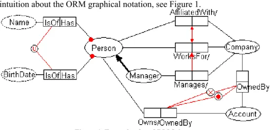
To get an intuition about the ORM graphical notation, see Figure 1.
Figure 1. Example of an ORM Schema
In Figure 1, concepts (also called object-types) are represented as ellipses, and relations are represented as rectangles. Each relation in ORM consists of one or more roles. For example, the relationship between the concepts Person and Account consists of the two co-roles, Owns and
OwnedBy. Notice that the notion of role in ORM means an argument of a relationship. This is unlike e.g. description logic languages, where the notion of role means a binary relation. Furthermore, relationships in ORM do not have names, but at least one of the roles in a relationship should have a linguistic label. In description logic, this relation can be formalized as (Person Owns.Account, Account OwnedBy.Person, OwnedBy Owns ).
In the following we explain each rule and its formalization:
Subsumption, is denoted by the thick arrow between Manager and Person (Manager Person).
Mandatory, is depicted as a dot on the line connecting Person and Name. It means each person should have at least one name (Person Has.Name).
Disjunctive mandatory, is depicted as a dot ( ) between the two OwnedBy roles. It means each account must be owned by at least a company or a person (Account
OwnedBy.Person OwnedBy.Company).
Exclusion, is depicted as between the two OwnedBy roles. It means that an account cannot be owned by a company and a person at the same time (OwnedBy.Person OwnedBy.Company).
Subset, is depicted as an arrow between the relationships WorksFor/ and Manages/;
which means that if a person manages a company then this person must be employed by that company (Manages WorksFor).
Equality, is depicted as a double-headed arrow between WorksFor/ and AffiliatedWith/;
which means that each person who works for a company is also affiliated with that company and vice versa (WorksFor AffiliatedWith).
External uniqueness, is depicted as (U) between Name and Birthdate; meaning that a person can be uniquely denoted by the combination of his Name and Birthdate.
ORM supports many other types of integrity rules graphically, which are not explained in this chapter for the sake of abbreviation. A complete list of ORM rules can be found in (Halpin, 2001) and their DL formalization in (Jarrar, 2007; Jarrar, 2007b). ORM also support derivation rules, which are not part of the graphical notation. ORM derivation rules are usually amended to the diagram in a textual language, called FORMAL (Halpin, 2005b). Similar to OCL for UML, FORMAL allows expressing complex rules that cannot be expressed in the ORM graphical notation.
We would like to remark also that ORM has recently been extended to allow business rules modalities, such as alethic and deontic rules. The typical ORM rules (as presented above) are used to restrict which data is possible and impossible (i.e. consistent or not). However, in some cases, these rules need to be deontic. In other words, deontic rules allow taking certain actions when rules are violated. These extensions to ORM have emerged from the usage of ORM rules within the business rules community, or especially during the finalizing of the OMG’s SBVR standard (Semantics of Business Vocabulary and Rules), where ORM concepts have been adopted. We chose not to include ORM’s deontic rules (as well as Dynamic rules) in this chapter as they are not yet implemented by any ORM tool, and they lack formal semantics. More about this extension to ORM can be found in (Halpin, 2005a).
Verbalization of ORM rules
It is indeed worthwhile to note that ORM is the historical successor of NIAM (Natural Language Information Analysis Method), which was explicitly designed (in the early 70’s) to play the role of a stepwise methodology, that is, to arrive at the “semantics'” of a business application’s data based on natural language communication.
Hence, ORM diagrams can be read easily by domain experts, and rules can be automatically verbalized into pseudo natural language sentences. All rules in a given ORM diagram can be easily translated into fixed-syntax sentences, which illustrates the verbalization capabilities of ORM and its closeness to natural language, if compared with other rule languages. For example, the rules presented in the previous example can be verbalized as the following:
Each Person Has at least one BirthDate. (Mandatory rule)
Each Account should be OwnedBy by Person or OwnBy a Company, or both. (Disjunctive Mandatory rule)
Same Account cannot be OwnedBy by Person and OwnBy a Company at the same time. (Exclusion rule)
If a Person Manages a Company then this Person WorksFor that Company. (Subset rule)
If a Person WorksFor a Company this Person is also AffiliatedWith that Company, and vice versa. (Equality rule)
Each Person can b identified by the combination of his Name and BirthDate. (External uniqueness rule)
One may notice that the underlined terms are originated from the ORM diagram and the other text is generated automatically. More sophisticated verbalizations are also possible. For example, (Jarrar et al., 2006) presents multilingual verbalization templates, which verbalizes ORM diagrams into many human languages including (English, German, Dutch, Italian, Spanish, Catalan, Arabic, Russian, Lithuanian, Chinese, and Vietnamese). See (Halpin et al., 2006) for other advanced verbalization of ORM. From a methodological viewpoint, this verbalization capability simplifies the communication with non-IT domain experts and allows them to better understand, validate, or build ORM diagrams.
ORM Formal Semantics and Reasoning
ORM's formal specification and semantics are well-defined. The most comprehensive formalization in first-order logic (FOL) was carried out in (Halpin, 1989). Furthermore, a complete formalization of ORM using the SHOIN description logic (i.e. OWL) can be found in (Jarrar, 2007b), and using the DLR description logic in (Jarrar, 2007).
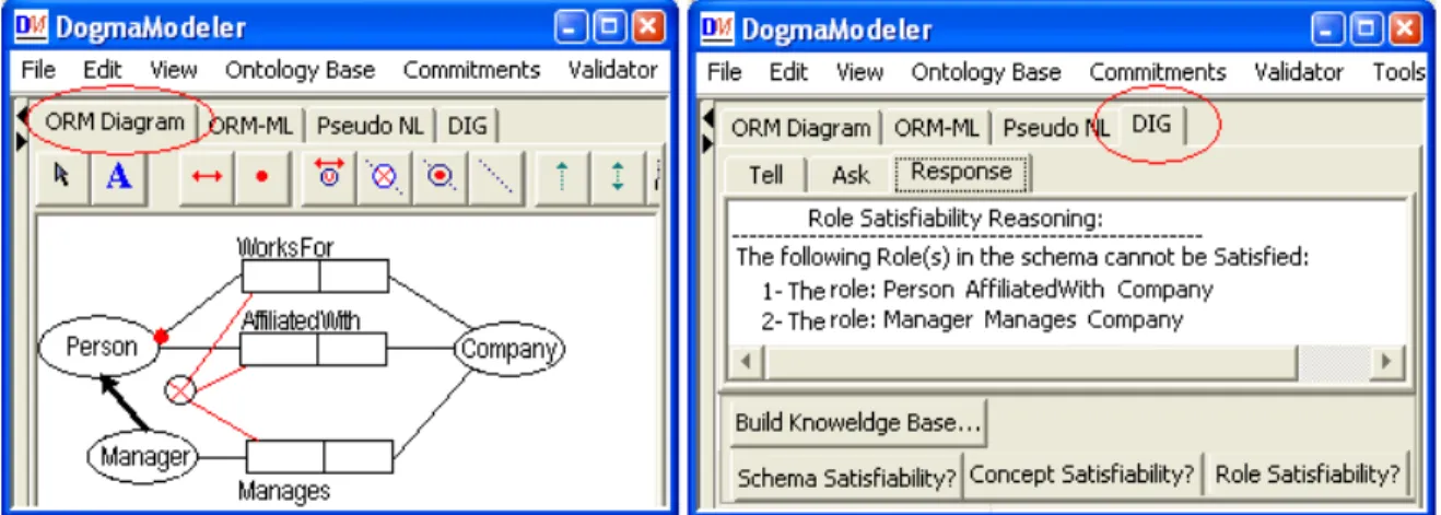
Based on these description logic formalizations, an ORM reasoner has been developed (as an extension to the DogmaModeler tool (Jarrar, 2005) in order to find rules that contradict each other. In DogmaModeler, ORM diagrams are mapped automatically into DIG, which is a description logic interface (XML-based language) that most reasoners (such as Racer, FaCT++, etc) support. DogmaModeler is integrated with the Racer description logic reasoning server which acts as a background reasoning engine. See a screenshot of DogmaModeler in Figure 2. The first window shows an ORM diagram, while the second window shows the reasoning results on this diagram. The results of the reasoning about the displayed ORM diagram indicate that the roles “AffiliatedWith” and “Manages” cannot be satisfied, because the mandatory and the exclusion constraints are conflicting each other. DogmaModeler currently implements three types of reasoning services: schema satisfiability, concept satisfiability, and role satisfiability.
When checking whether an ORM diagram contains rules that contradict each other, current description logic reasoners (including the approach presented above) can only provide a list of the unsatisfiable concepts. In other words, there is no way to tell users what causes a certain concept to be unsatisfiable, i.e. (which) rules are contradicting each other that cause this concept to be unsatisfiable. User have to debug and find contradictory rules themselves, which is indeed very difficult for people who are not familiar with logic.
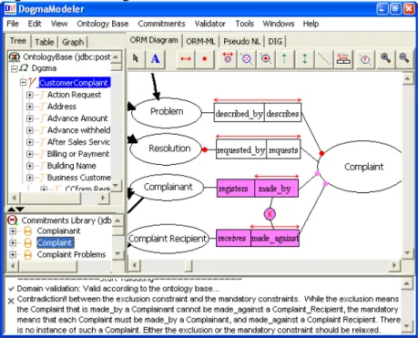
Another novel approach for reasoning about ORM rules has been developed, called Pattern-based reasoning (Jarrar et al, 2008). This approach is seen as a complementary to the above DL-based approach. This approach is designed to empower non-IT business rule modelers with a user-friendly reasoning and debugging mechanism. It does not only point out which concepts are unsatisfiable, but also which rules cause this unsatisfiability (i.e. which rules are contradicting each other), and how to resolve this contradiction. All of this is verbalized in a pseudo natural language message, generated automatically by DogmaModeler. The screenshot in Figure 3 illustrates DogmaModeler’s support of pattern-based reasoning, see the highlighted contradictions and generated message at the bottom.
Figure 3. DogmaModeler’s support of pattern-based reasoning
This example was taken from a real-life application (Jarrar, 2008), which happened during the development of the CContology (a regulatory ontology about e-commerce complaints). The CContology has been developed by about 50 lawyers and business experts. We found this way of reasoning/debugging rules is indeed very helpful for those non-IT people. More about our experience on using this approach can be found in (Jarrar et al, 2008). It is important to note that this pattern-based reasoning approach is not complete from a theoretical viewpoint, i.e. there is no guarantee that all contradictions will be caught. However, from a practical viewpoint, most of the contradictions can be caught indeed. DogmaModeler combines both the description logic approach (which is theoretically complete) with the pattern-based reasoning approaches (which is very practical) in a complementary way.
Not only verbalization and reasoning about ORM rules, but the art of ORM engineering is generally rich. From a research perspective, we would like to point to several lessons and
techniques in ORM that can be applied to enrich other rule approaches, such as abstractions (Vermeir, 1983; Campbell et al., 1996), evolution (Proper, 1997), transformation and optimization (Halpin et al, 1996), modularization and full automatic composition of rules (Jarrar, 2005), methodological elicitation of rules (Halpin, 2001), concept definition and glossaries (Jarrar, 2006b), conceptual queries (Bloesch et al, 1996), among others.
UML/OCL FOR RULE MODELING
The Unified Modeling Language (UML) (OMG, 1999) is a visual specification language for object modeling, widely used in software development for object-oriented modeling and analysis. It became an official standard adopted by the Object Management Group in November 1997. The UML modeling notation is developed by James Rumbaugh in 1994 and is strongly influenced by the Object Modeling Technique (OMT), the Booch method, and the Objectory method. The language is defined by means of Meta-Object Facility (MOF) (OMG MOF, 2008) metamodel and is extensible by means of profiles and stereotypes. It includes a graphical notation for creation of an abstract model of a system, called UML model. In order to represent a part of a system model, different graphical notations, called diagrams, are used. The UML 2.0 has 13 diagram types for modeling a system from different perspectives: structure diagrams, behavior diagrams, and interaction diagrams. In this chapter only UML class diagrams are considered, since they are used to define rule vocabularies in terms of classes, class attributes, and relationships between the classes.
A Business Vocabulary and Rule in UML
Figure 4 depicts a UML class diagram of a case study about car rental. It illustrates the graphical notation of UML and shows how it can be used for representing simple business rules.
startDate endDate /discount Rental dateOfBirth Person DrivingLicense OneWayRental Branch pickupBranch 1 * returnBranch 1 * * * hasRental 1 0..1 isAuthorizedWith AuthorizedDriver GoldCustomer BadExperienceRecord 1 * has
Classes in UML are denoted by rectangles with a class name, and compartments for attributes and operations. For instance, the main class in Figure 4 is Rental with attributes startDate and
endDate, and a derived attribute discount. The slash before the attribute name means that the value of this attribute is computed by means of a derivation rule. UML has several types of relationships for modeling logical connections. For instance, UML Link is the basic relationship between objects. It is represented as a line connecting two or more object rectangles.
An example of an association in Figure 4 is isAuthorizedWith, which connects rectangles, which represent classes Person and DrivingLicense. Association ends may also have names, called role names. An example of a role name in Figure 4 is pickupBranch.
The classes Rental and Branch with corresponding associations are read as “Every Rental has a
Branch as a returnBranch and as a pickupBranch”. Association ends can be annotated with multiplicities also called cardinality restrictions. For instance, multiplicities of the
isAuthorizedWith association are 1 and 0 or 1. This is read as “Every Person is authorized with at most one DrivingLicense” and “Every DrivingLicense has exactly one Person”. These two sentences, which verbalize cardinality restrictions, are examples of business rules, which can be expressed using the graphical notation of UML class diagrams. The semantics of cardinality restrictions is that they restrict a number of objects of a class, participating in an association. Other class diagram relationships like generalization can also express rules. For instance, the
OneWayRental class is a subclass of Rental. This means any instance of OneWayRental is also an instance of a Rental, which can be verbalized in more human-readable manner “Every OneWayRental is a Rental”.
Unlike the graphical expressivity of ORM, UML class diagrams are not expressive to capture more complex rules graphically. For this purpose OMG has released the Object Constraint Language (OCL), which is used to express sophisticated constraints on class diagrams. The language has textual syntax and rules can be placed on a diagram in comment boxes or listed separately. The syntax of OCL is very expressive and mainly designed for IT specialists and software developers. The full OCL specification (OMG, 2003) explains how to use the full power of the language. Here we introduce some OCL basics, give examples of business rules from the car rental case study.
Integrity rules in UML/OCL
We start with an example of a business rule “The start date of the rental must be before its end date”. This rule in OCL:
Context Rental inv:
self.startDate < self.endDate
Each OCL expression is written in the context of an instance of a specific class, which is also called a context classifier. If the constraint is put on the diagram, then the context class is connected with a dotted line to the rectangle, containing constraint text. Integrity rules in OCL are expressed by means of invariants. An invariant contains an OCL expression of type Boolean. This expression must be true for all instances of the context classifier. In our examples, the start date must be before the end date for all instances of the Rental class at any time. An instance of the context classifier is denoted by the word self, which can be considered as a variable of the class Rental. The self reference can be omitted.
OCL expressions can refer to properties, which are attributes, association ends, and side-effect-free operations. For instance, in our example the subexpression self.startDate is the value of the attribute startDate for each instance of the class Rental.
Using the opposite association end name it is possible to navigate from a specific object to other objects in order to access their properties, for instance, in the context of the class Rental we can navigate to the Branch by self.returnBranch. The type of such expression depends on the multiplicity of the association. In case of our example the multiplicity is 1, therefore the expression is of type Branch. If multiplicity is more than one, then the type of the expression is
Set or OrderedSet, which are special OCL types, like some others. These types have properties, which can be accessed using an arrow “->”. For instance, if we have a rule “An authorized driver must have no more than 3 bad experience records”, then we can write this in OCL:
Concext AuthorizedDriver inv: badExperience->size()<3
The size() operation is defined for the type Set and returns the amount of objects in the seti. If the name of the association is missing, then the name of the class, starting with the lowercase is used. Let us consider an integrity rule “Each Person who has a Rental must be authorized with a Driving License”. Multiplicities of the association “Person has Rental” and “Person is authorized with a Driving License” are greater than 1, therefore the value of the expression
self.rental is a Set. This rule in OCL: Context Person inv:
self.rental->exists(y:Rental) implies self.drivingLicense->exists(z:DrivingLicense)
The exists() operation is defined for sets. Its semantics is close to the semantics of the existentially quantified formula in the first order logic: there exists at least one rental for a personii. Another example of an integrity rule is “If the return branch of the rental is not the same as pickup branch, then it is a one way rental”. This rule in OCL:
Context Rental inv:
pickupBranch <> returnBranch implies self.oclIsKindOf(OneWayRental)
This invariant is expressed in the form of implication, using the “implies” operationiii. The expression self.oclIsKindOf(OneWayRental) has type Boolean. The operation
oclIsKindOf(T:OclType):Boolean is predefined in OCL and applies to all objects. It results in true if either T is the direct type or one of supertypes of self.
Derivation rules in OCL
An OCL expression can be used to calculate the derived value of an attribute or association end. For instance, the rule calculates the value of the attribute, such as “Gold customer gets 10 percent discount”. In OCL:
Context Rental::discount:Real
derive: if self.person.oclIsKindOf(GoldCustomer) then 10.0 endif
The type of the expression must conform to the type of the attribute (discount). In our example the if-then expression is of type real since then-part contains the real 10.0. It is also possible to derive an association end. The expression must conform to the classifier if the multiplicity at the association end is at most one, otherwise the expression should be of type Set or OrderedSet.
(URML) UML-BASED RULE MODELING LANGUAGE Introduction
UML-based Rule Modeling Language (URML, 2008) is developed as a part of the European research project REWERSE (www.rewerse.net) by the Working Group I1 (http://www.rewerse.net/I1). One of the main goals of this group was to provide a comprehensive graphical notation, which can be used for rule modeling in UML. For this purpose UML metamodel is extended with the concept of a rule, and some graphical symbols have been assigned to different rule parts: rules, conditions, conclusions, actions, and events (URML metamodel, 2008).
Derivation Rules in URML
Let us consider a sample business rule: “If the return branch of the rental is not the same as pickup branch, then it is a one way rental”. In the previous UML/OCL section, we have modeled this rule as an integrity constraint. However, it also can be modeled as a derivation rule, using URML. This duality comes from the ambiguity of the natural English language, which has been used initially for expressing the rule. It is important to know, that the decision about the rule type depends on the application, but not on the modeling language. If the intended business behavior of a rule is to check a constraint at run-time and to prohibit the existence of an object, which does not comply with the rule, then it can be modeled and executed as an integrity constraint. If the intended business requirement is to query the database for one way rentals, then the rule should be modeled as a derivation rule.
The rule on Figure 5 is depicted by the circle with the “DR” inside, which means “derivation rule”. The condition of the rule is depicted as an arrow with the annotation text “pickupBranch <> returnBranch”, which is called filter expression, because it filters out instances of the condition classifier Rental. The condition arrow is also annotated with the rule variable x.
Figure 5. Derivation rule with classification condition and conclusion
The semantics of this rule can be captured by the following expression in a logic programming language:
OneWayRental(x)<-Rental(x) and pickupBranch(x)<>returnBranch(x) URML has three types of conditions:
Classification condition is depicted as an arrow from a UML class to the rule circle. The arrow near the class is annotated with a rule variable of the class. In the example rule on Figure 5 the arrow from the class Rental to the rule circle is a classification condition (Rental(x)).
Role condition is depicted as an arrow from a UML association end to the rule circle and is annotated with a rule variable of the association end class.
Association condition is depicted as an arrow from a UML association to the rule circle and is annotated with two rule variables, each of the corresponding class at association ends (see Figure 6 for example).
Each condition arrow can be annotated with a filter expression, which is a Boolean expression in OCL, but an opaque filter may be used for some vendor-specific implementation (pickupBranch <> returnBranch on Figure 5). A filter is used to filter instances of a conditioned classifier, which is either a class, or an association end, or an association.
URML has four types of conclusions:
Classification conclusion, which is depicted as an arrow from the rule circle to the derived class. The arrow can be annotated with a variable of the derived class. In the example rule on Figure 5 the arrow from the rule circle to the class OneWayRental is a classification conclusion (OneWayRental(x)).
Role conclusion is depicted as an arrow from the rule circle to the derived association end and is annotated with a variable of the association end class.
Attribution conclusion is depicted as an arrow from the rule circle to the class, which contains the derived attribute. The arrow is annotated with the variable of the class and with the property-value statement, which specifies values for the class attributes.
Association conclusion is depicted as an arrow from the rule circle to the derived association and annotated with two variables, each of the corresponding class at association ends.
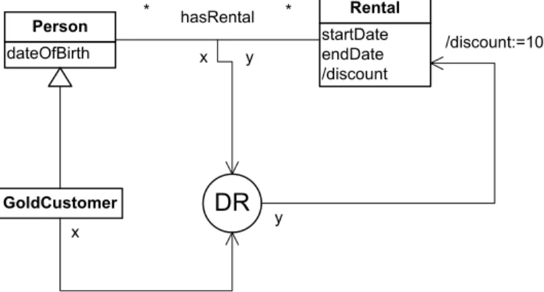
Let us consider another derivation rule, which calculates the rental discount, depending on the customer type “Gold customer gets 10% discount” (Figure 6).
dateOfBirth Person GoldCustomer startDate endDate /discount Rental * * hasRental DR x y y x /discount:=10
Figure 6. Derivation rule, which derives an attribute value
This rule has one classification condition (x is a GoldCustomer), one association condition (x hasRental y), and one attribution conclusion (the discount of Rental y is 10).
The semantics of this rule can be captured by the following expression in a logic programming language:
The difference between the rule diagram on Figure 6 and the initial rule expression “Gold customer gets 10% discount” is that: the latter does not have the verbal construct for the association condition. The rule on the diagram is so called safe rule, which means that all variables in the head of the rule must be universally quantified, i.e. appear in the condition part. If we drop the association condition, then the variable y does not appear in the condition part at all. Non-safe derivation rules cannot be deployed into the rule execution system: the Selective Linear Definite clause resolution algorithm (Kowalski, 1971), which is used for query resolution, does not necessarily stop if the rule base contains non-safe rules. Therefore, it is important to track the safety of rules when modeling. A graphical notation may help in avoiding such mistakes since variables, participating in the head of the rule are immediately visible, while the initial rule in English may be ambiguous or incomplete.
Production rules in URML
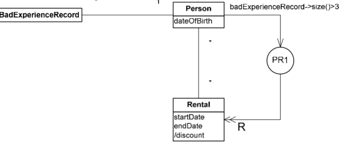
Production rules are the most widely used type of rules in industry. However, the lack of formal semantics for these rules and variety of implementations from different vendors make them difficult to model at the computational-independent level. In order to resolve this, recent OMG activities towards production rules standardization are about to become the standard for production rule actions (OMG PRR, 2007). URML is designed keeping OMG recommendations in mind. We explain URML facilities in modeling production rules and start with an example “If a person has more than 3 bad experience records then cancel his rental”. The rule diagram is depicted on the Figure 7.
Figure 7. Production rule with retract action
The condition part of the rule is the same as for derivation rules, but the action is depicted by the arrow with the double-head and annotated with the “R” character, which means Retract Action. URML is designed following the current OMG proposal (OMG PRR, 2007), which defines three action types:
Update action is used to update properties of an object, for instance, give 10% discount. The action is depicted by the arrow from the rule circle to the class, which instance has to be updated. The arrow is annotated with the property-value statement, which specifies new values for object properties. This action is similar to the attribution conclusion of derivation rules.
Assert action creates new instances in the working memory if conditions hold. It is depicted by the arrow from the rule circle to the class, which instance has to be created.
Retract action removes instances from the working memory if condition holds. It is depicted by the arrow from the rule circle to the class, which instances have to be retracted.
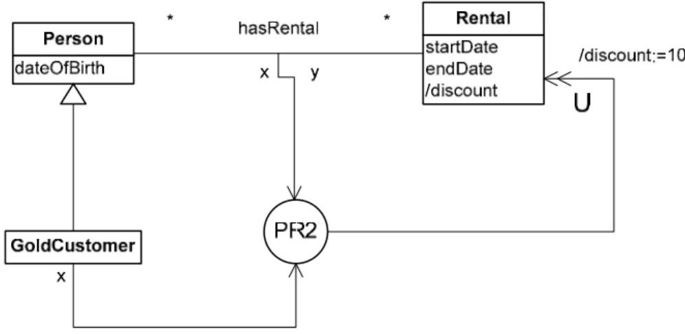
Note that the filter expression in the condition of the rule in Figure 7 uses OCL syntax. The next example shows how the derivation rule from Figure 6 is modeled using a production rule (Figure 8).
Figure 8. Production rule with update action
In this example (Figure 8), the action part is an update action, which assigns the new value to the
discount attribute. Since there is not yet a standard for production rules, its URML graphical notation is also in beta stage. However, it already can be used for rule modeling and there are case studies implemented with the help of URML (Wagner et al., 2007).
Reaction rules in URML
The modeling support for reaction rules in URML is still under development. However, it is possible to model reaction rules with one atomic triggering event, which is denoted by a class with the <<event>> stereotype.
Figure 9. Reaction rule in URML
An example of a reaction rule is in Figure 9. The rule is “On customer book item request, if the item is available, then decrease amount of items in stock”. Here “on customer book item request” is an event, which is depicted in Figure 9 as a class CustomerBookRequest with the stereotype <<event>>. This class is a part of the business domain, modeled in UML. The event class is
connected with the rule circle by means of the triggering event arrow (with the bold arrow head). The update action of this rule updates the quantity of book items in stock, an OCL expression is used to express the new quantity.
The graphical notation for composite events is not yet supported. Business rules, which can be modeled as reaction rules and further executed in a reaction rule engine, are not widely used at the moment. There are two issues, which are the subject for the current and forthcoming research: 1-the complexity of the event algebra, and 2-how to recognize composite events in the implementation of an engine.
URML tool support
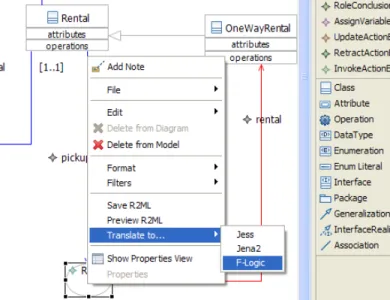
The URML is supported by the Strelka tool (REWERSE I1 Strelka tool, 2006; Lukichev & Wagner, 2006). The tool supports graphical notations for UML and URML and the created rule models can be translated into a specific rule language, for instance Jena 2 or F-Logic. Figure 10 depicts a screenshot of the tool, where a rule, represented graphically, is translated into Jena 2.
Figure 10. Translating rule into a rule language in Strelka The result of the translation is depicted in Figure 11.
Figure 11. The rule in Jena
Therefore, the tool can be used for development of rule-based applications, as in following the scenario: rules are modeled, using URML, then they are translated a particular rule language and acceptable by a rule engine. A real-life business case study has been implemented as such and can be found online (see Giurca, 2007).
COMPARISON OF DIFFERENT GRAPHICAL NOTATIONS
A full mapping between UML and ORM can be found in (Halpin, 2001). According to this mapping, “UML’s implementation concerns render it less suitable for developing and validating a conceptual model with domain experts”. And this “can be remedied by using fact-oriented approach for the conceptual modeling, from which class diagrams may be derived”. Indeed, ORM seems closer to the conceptual level, while UML is closer the technical level, as we shall explain shortly. This is natural because UML was originally designed to model object-oriented programs graphically, while ORM was originally designed to model information systems (facts and their rules) at the conceptual level. In other words, ORM is more suitable for modeling a domain starting from the communication between domain experts, while UML is more suitable starting from the communication between software engineers.
In the following, we discuss UML/OCL, URML, and ORM on the basis of these criteria, as used in (Halpin, 2001):
Expressiveness of a language is a measure of what it can be used to say;
Clarity of a language is a measure of how easily it can be understood and used;
Semantic stability is a measure of how well rule models retain their original intent when face changes in the rule base of in the rule vocabulary.
Validation mechanisms are ways in which domain expert can check whether the rule model matches the intended business rules.
Expressiveness. It is indeed difficult (or rather we believe it is nincorrect) to quantify the difference of what two modeling languages can express. This is because each language has its
own epistemology1 of structuring and expressing knowledge, and what can be expressed directly in a language might be emulated (or indirectly achieved somehow) by another. We found the three languages presented in this chapter are indeed expressive, but each within different communities of practice. An additional remark is that, what cannot be graphically expressed in UML, might be expressed by its OCL textual formal language. Similarly, what cannot be expressed by the ORM graphical notation might be expressed by its FORMAL textual language (Halpin, 2005b). Compared with the graphical notation of UML, we found the graphical notation of ORM is more expressive, because many rule types can be expressed graphically. For example, exclusive mandatory, external uniqueness, predicate subset, equality, exclusion, value, external frequency, symmetry, intransitivity, acyclicity, among other rule types that ORM supports graphically, do not have graphical support in UML. On the other side, the UML’s OCL seems more sophisticated compared the ORM’s FORMAL. Unlike OCL, which is widely used and supported by many tools, FORMAL has no tool support and it is not widely known even among the ORM community. The URML graphical notation supports production rules and reaction rules, which are not supported in UML/OCL and ORM. However, being an extension of the UML/OCL, URML inherits some of its drawbacks. For instance, it cannot visualize integrity constraints, since it is assumed they are expressed using non-intuitive OCL syntax.
Clarity. The clarity criterion depends not only on the language itself but also on the rule modeler qualification. Business experts may be confused with the complexity of the OCL syntax, while evaluations of ORM among domain experts have shown that its graphical notation can easily be understood by lawyers and business experts, see (Jarrar, 2008). It is not only the smoothness of ORM diagrams that makes it clearer, but more importantly, its closeness to natural language. As shown in the ORM section above, the verbalization capabilities of ORM (compared with UML and URML) make it easier to understand by non-IT people. On the other hand, software architects and developers prefer OCL in spite of its complexity. This is mainly due to its object-orientation and tools support for code generation. URML being up to now mainly evaluated in academia, however, on realistic case-studies, has demonstrated its clarity and easiness of adaptation among students. Majority of business rules are rather simple and if they do not require complex filter expressions in OCL syntax, they can easily be modeled using URML even by novice rule modelers.
Stability. After deploying a set of business rules, these rules might evolve or need to be changed. The more changes a modeler has to perform to cope with a change of business rule, the less stable the language is. For example, if an attribute of a class evolved to be an independent class, the process of changing this attribute into a class (or vice versa) might trigger several change on the whole diagram, and thus change on its underpinning implementations. Compared with UML, ORM is considered more stable and immune to changes. This is because ORM does not distinguish between class and attribute. Both are equally treated as independent concepts in ORM. Consider, for example, a fact type Employee-WasBornIn-Country, which corresponds to the UML class Person with an attribute birthplace. If we later decide to introduce the population of a birthplace country, then the new class Country has to be added to the model with two attributes: name and population and new association between class Person and class Country has
1 The epistemology of a language refers to its constructs and primitives that are to structure and
to be created. This is a significant change to the model, which is avoided in ORM since “wherever an attribute is used in UML, ORM uses a relationship instead”.
On the other hand, this UML duality in modeling relationships as attributes or as reference properties and associations is a conceptual part of the object-oriented approach (encapsulation) and fits the needs of software developers. There are many supplementary methodologies and software techniques for UML model refactoring and transformation, for instance, Query View Transformations, which allows transforming models and preserves the integrity.
Validation. All of the presented methodologies have validation mechanisms in order to check the conformance of rule models to the intended application. Notice that the notion of validation here does not refer to satisfiability reasoning (to know whether there are rules that contradict or imply each other), but we rather refer to the validation guide offered by the language to know whether the rules are exactly what a user intended to model. This kind of validation cannot be fully automated, as one would not know what users have in mind. In ORM the validation is performed by means of verbalization: representing rules in pseudo-natural human sentences. After modeling a rule graphically, one can see the corresponding verbalization of this rule, which helps him confirm that he did not misunderstand the semantics of that rule. In addition to these verbalization checks, most ORM tools support population checks, i.e. allowing users to insert correct and incorrect data facts and see whether these facts in consistent with rules or not. The validation of UML/OCL models by means of verbalization is a non-trivial task and to the best of our knowledge there are no established approaches to verbalization of OCL constraints. However, the verbalization is just one possible mean of validation. Software engineering methodologies, which employ UML, for instance, Rational Unified Process, propose guidelines for models validation. URML supports rule validation by means of verbalization. Although it is not sophisticated compared with ORM, but URML models can be serialized into a rule language with XML syntax. Rules, expressed in this XML language, can be unambiguously verbalized and made human-readable (R2ML Verbalizer, 2006; Lukichev & Wagner, 2006b).
CONCLUSION
In this chapter we have introduced graphical notations of two industrial rule modeling methodologies: UML and ORM, and the upcoming URML. While UML is aimed at software engineers and IT professionals, ORM is more intuitive and easy to use by business experts, who may not be familiar with or not willing to learn complex textual syntax of OCL. The conceptual ORM models, developed by communicating with business experts can be mapped into UML models, if needed, and then translated further to executable code or to some formal rule language for a specific rule platform. At the same time, URML provides a comprehensive graphical notation for various rule types, which makes it attractive not only to IT experts, but also for people without strong technical background.
Concerning the further development, URML graphical notation will be proposed as a (part of) OMG standard for rule modeling, in particular, for modeling production rules.
UML/OCL is already an OMG standard, which is widely adopted in the software engineering community. In spite of large amount of UML case tools, the support of OCL is still growing.
ORM is becoming more and more popular is several areas and communities. As mentioned earlier, the ORM graphical notation is being extended to include dynamic and deontic rules (called ORM 2). The ORM concepts including these extensions have been adopted by OMG in its recent SBVR standard (Semantics of Business Vocabulary and Rules).
REFERENCES
Baba, P. (2006). Using ORM-based Models as a Foundation for a Data Quality Firewall in an Advanced Generation Data Warehouse. Proceeding of ORM'06. Springer LNCS. 2006 Barbuceanu, M., Gray, T., Mankovksi, S. (1999) Roles of Obligations in Multiagent
Coordination, Applied Artificial Intelligence, 13(1), 11–38, 1999
Berztiss, A., Bubenko, J. (1995) A software process model for business reengineering.
Proceedings of ISDO’95. Chapman and Hall. 1995
Bird, L., Goodchild, A., Halpin, T. (1999). Object Role Modelling and XML-Schema. Proc. of the 19th Int. Conf. on Conceptual Modeling ER’02. Springer LNCS. 1999
Bloesch, A., Halpin, T. (1996). ConQuer, a conceptual query language, Proc. of ER’96. Springer LNCS 1157. 1996
Brockmans, S., Volz, R., Eberhart, A., Loeffler, P. (2004). Visual modeling of OWL DL ontologies using UML. Proceedings of the Third International Semantic Web Conference,
3298, 198-213.
Campbell, L., Halpin, T., Proper, H. (1996). Conceptual Schemas with Abstractions – Making flat conceptual schemas more comprehensible. Data & Knowledge Engineering, 20(1), 39– 85, 1996
CaseTalk website: http://www.casetalk.com/php/ (October 2006)
Demey, J., Jarrar, M., Meersman, R.(2002). A Conceptual Markup Language That Supports Interoperability between Business Rule Modeling Systems. Proc. of the 10th Int. Conf. on Cooperative Information Systems (CoopIS 02). Springer LNCS 2519. 2002
De Troyer, O., Casteleyn, S., Plessers, P. (2005). Using ORM to Model Web Systems.
Proceeding of ORM'05. Springer LNCS. 2005.
Dumas, M., Aldred, L., Heravizadeh, M., terHofstede, A. (2002). Ontology Markup for Web Forms Generation. WWW'02 Workshop on Real-World Applications of RDF and the Semantic Web. 2002.
Giurca, A. 2007. Using URML and R2ML in a Financial Services Use Case (implemented with JBoss Rules and JenaRules). Retrieved Thursday May 1, 2008, http://oxygen.informatik.tu-cottbus.de/rewerse-i1/?q=node/33
Halpin, T. (2001). Information Modeling and Relational Databases. 3rd edn. Morgan-Kaufmann. (2001)
Halpin, T. (1989). A logical analysis of information systems: static aspects of the data-oriented perspective. PhD thesis, University of Queensland, Brisbane. Australia. (1989)
Halpin, T., Proper, H. (1995). Subtyping and polymorphism in object-role modeling. Data & Knowledge Engineering 15(3). (1995) pp. 251–281
Halpin, T. (2004). Business Rule Verbalization. In Doroshenko, A., Halpin, T., Liddle, S., Mayr H. (eds): Information Systems Technology and its Applications, 3rd International Conference (ISTA'2004), LNI 48 GI ISBN 3-88579-377-6, (2004) pp:39-52.
Halpin, T., Evans, K., Hallock, P., MacLean, W. (2003). Database Modeling with Microsoft® Visio for Enterprise Architects. Microsoft® Visio. Morgan Kaufmann, San Francisco. 2003 Halpin, T. (2002). Join Constraints. Proceedings of the EMMSAD'02. 2002
Halpin, T. (2005). Objectification. Proceddings of the EMMSAD’05, at CAiSE 2005. 2005 Halpin, T. (2005a). ORM 2. Proceedings of the OTM Workshops 2005, Springer LNCS, 2005 Halpin, T. (2005b). FORML Position paper for W3C Workshop on Rule Languages for
Interoperability. Proceeding of the workshop Rule Languages for Interoperability. W3C. 2005
Halpin, T., Curland, M. (2006). Automated Verbalization for ORM 2. OTM'06 Workshops. Springer LNCS. 2006
Halpin, T., Proper, H. (1996). Database Schema Transformation & Optimization. Proceedings of the 14th International Conference on Conceptual Modeling, Springer LNCS, vol. 1021.1996 Infagon website: http://www.mattic.com/Infagon.html (October 2006)
Jarrar, M. (2005). Towards Methodological Principles for Ontology Engineering. PhD Thesis. Vrije Universiteit Brussel, Belgium. May 2005
Jarrar, M. (2006). ORM Markup Language, version 3. Technical Report. Vrije Universiteit Brussel, Belgium. August 2006
Jarrar, M. (2006b). Towards the notion of gloss, and the adoption of linguistic resources in formal ontology engineering. Proceedings of the WWW2006 conference. ACM Press. 2006 Jarrar, M., Keet, M., Dongilli, P. (2006). Multilingual verbalization of ORM conceptual models
and axiomatized ontologies. Technical Report. Vrije Universiteit Brussel, Belgium. 2006 Jarrar, M. (2007). Towards Automated Reasoning on ORM Schemes. -Mapping ORM into the
DLR_idf description logic. Proceedings of the 26th International Conference on Conceptual Modeling (ER 2007). Springer, LNCS, Volume 4801, Pages (181-197), 2007.
Jarrar, M. (2007b). Mapping ORM into the SHOIN/OWL Description Logic- Towards a Methodological and Expressive Graphical Notation for Ontology Engineering. In OTM workshops, proceeding of the International Workshop on Object-Role Modeling (ORM'07). Springer LNCS Volume 4805, , Pages (729-741), 2007
Jarrar, M. (2008). Towards Effectiveness and Transparency in e-Business Transactions, An Ontology for Customer Complaint Management. A book chapter in "Semantic Web Methodologies for E-Business Applications". IGI Global. ISBN: 978-1-60566-066-0. Chapter 7. (October 2008)
Jarrar, M., Heymans, S. (2008). Towards Pattern-based Reasoning for Friendly Ontology Debugging. Journal of Artificial Intelligence Tools. Volume 17. No.4. World Scientific Publishing. August 2008.
Kowalski, R., Kuehner, D. (1971). LinearResolution with Selection Function. Artificial Intelligence. Volume 2. pp. 227-260.
Kremer R. (1998). Visual Languages for Knowledge Representation. Eleventh Workshop on Knowledge Acquisition, Modeling and Management.Banff, Alberta, Canada. April 1998. Lukichev, S., Wagner, G. (2006). UML-Based Rule Modeling with Fujaba. Proceedings of the
4th International Fujaba Days 2006, University of Bayreuth, Germany. Pages: 31 – 35. Lukichev, S., Wagner, G. (2006b). Verbalization of the REWERSE I1 Rule Markup Language.
REWERSE IST 506779 Report I1-D6.
North, K. (1999). Modeling, Data Semantics, and Natural Language. New Architect magazine. 1999.
NORMA website http://sourceforge.net/projects/orm (October 2006)
OMG (1999). Unified Modeling Language Specification. http://www.omg.org/uml.
OMG (2003). Object Constraint Language (OCL), v2.0. http://www.omg.org/docs/ptc/03-10-14.pdf
OMG MOF (2008). OMG’s MetaObject Facility, Retrieved 2 May 2008, http://www.omg.org/mof/
OMG PRR (2007). Production Rule Representation (PRR), Beta 1, OMG Adopted Specification. http://www.omg.org/docs/dtc/07-11-04.pdf
MDA (2008). Model Driven Architecture, Retrieved 2 May 2008, http://www.omg.org/mda/ Proper, H. (1997). Data Schema Design as a Schema Evolution Process. Data & Knowledge
Engineering, 22(2), 159–189, 1997
Proper, H., van der Weide, T., ter Hofstede, A. (1993). Formal definition of a conceptual language for the description and manipulation of information models. Information Systems, 18(7):471–495, October 1993
Proper, H., Bleeker, A., Hoppenbrouwers, S. (2004). Object-role modelling as a domain.
Proceedings of the Workshop on Evaluating Modeling Methods for Systems Analysis and Design. Latvia. 2004.
R2ML verbalizer (2006). Website: http://oxygen.informatik.tu-cottbus.de/verbalization/index.jsp REWERSE I1 Strelka tool (2006). Strelka – A UML-based Rule Modeling Tool. Retrieved
Thursday May 1, 2008, http://oxygen.informatik.tu-cottbus.de/rewerse-i1/?q=Strelka Ross, R. (2003). Principles of the Business Rule Approach. Addison-Wesley.
Ross, R. (1997). {The Business Rule Book: Classifying, Defining and Modeling Rules, 2nd edition. Boston (MA): Database Research Group, Inc..
Taveter, K. (2001). Agent-Oriented Business Modeling and Simulation. PhD thesis, Tallinn Technical University.
URML (2008). UML-based Rule Modeling Language. Website http://oxygen.informatik.tu-cottbus.de/rewerse-i1/?q=URML
URML Metamodel (2008). Retrieved Thursday May 1, 2008, http://oxygen.informatik.tu-cottbus.de/strelka/URML-Metamodel.htm
Vermeir, D. (1983). Semantic Hierarchies and Abstraction in Conceptual Schemata. Journal of Information Systems. Vol. 8, No. 2. (1983) pp. 117–124
VisioModeler, (2006). download site: http://www.microsoft.com/downloads/ results.aspx?displaylang=en\&freeText=VisioModeler (October 2006)
Wagner, G., Antoniou, G., Tabet, S., Boley, H. (2004). The Abstract Syntax of RuleML - Towards a General Web Rule Language Framework. Proceedings of the IEEE/WIC/ACM International Conference on Web Intelligence (WI 2004), 628-631.
Wagner, G., Giurca, A., Lukichev, S., Nicolae, O., Daconescu, M. (2007). Case Study 1: Userv product Derby 2005. REWERSE IST 506779 Report I1-D9.
i Such a rule can be graphically expressed in ORM, which is called frequency constraint. A cardinality of 3 can be placed on the relationship between Person and BadExperience (see Jarrar 2007).
ii This rule is called Subset in ORM, and can be represented graphically, as an arrow between roles: the person’s role connected to Rental, the perosn’s role connected to DrivingLicense, See a similar example in (Jarrar 2007, 2007b) iii This rule can be similarly expressed in ORM using FORMAL. However it can also be achieved graphically, but requires some remodeling.