Verifying Dynamic Aspects of UML Models
Mathias Soeken
Robert Wille
Rolf Drechsler
Institute of Computer Science, University of Bremen
28359 Bremen, Germany
{
msoeken,rwille,drechsle
}
@informatik.uni-bremen.de
Abstract—The Unified Modeling Language (UML) as a de-facto standard for software development finds more and more application in the design of systems which also contain hardware components. Guaranteeing the correctness of a system specified in UML is thereby an important as well as challenging task. In recent years, first approaches for this purpose have been introduced. However, most of them focus only on the static view of a UML model.
In this paper, an automatic approach is presented which checks verification tasks for dynamic aspects of a UML model. That is, given a UML model as well as an initial system state, the approach proves whether a sequence of operation calls exists so that a desired behavior is invoked. The underlying verification problem is encoded as an instance of the satisfiability problem and subsequently solved using a SAT Modulo Theory solver. An experimental evaluation confirms the applicability of the proposed approach.
I. INTRODUCTION
The Unified Modeling Language(UML) is considered as a de-facto standard for software development [1]. By providing several diagram types, it enables the specification of com-plex systems on different levels of abstraction. This includes the global view on the system as a whole as well as the detailed description of one particular component. With in-creasing complexity of today’s hardware systems, researchers also investigated the integration of UML in the design of hardware, e.g. embedded systems [2], [3]. In the context of hardware/software co-design, systems are specified first on a high level of abstraction, before partitioned into respective hardware- and software-components in a later step.
A UML model includes constructs such as classes, associ-ations, attributes, or operations in order to specify a system. Moreover, theObject Constraint Language(OCL) [4] is used to extend a UML model by additional textual constraints that define further properties and relations between the respective parts of the model. Analogously, pre- and post-conditions can be added to an operation specifying (1) the requirements in which an operation can be called and (2) the desired system state after the execution of the operation. As a result, static system states and dynamic sequences of operations can be modeled.
A crucial requirement in the design process of a complex system is its verification aimed to ensure the correctness. However, with increasing design complexity, it is decisive how and when verification is firstly being employed. Due to shortening time-to-market demands, design flaws need to be detected as early as possible. Being an abstract methodology for specifying systems, UML serves as a good starting point. First verification approaches considering the static view of a UML model have already been introduced in the recent past.
978-3-9810801-7-9/DATE11/ c2011 EDAA
These approaches consider verification tasks such as consis-tency, independence, and consequences [5]. Amongst others, enumerative methods (e.g. [6]), theorem provers (e.g. [7]),
Constraint-Satisfaction-Problem (CSP) solvers (e.g [8]), and
Boolean satisfiability (SAT) (e.g. [9]) have been applied for this purpose. However, in all these approaches, operations in the UML model (i.e. the dynamic view of a specification) are not considered. In contrast, [10] and [11] present approaches for the validation of dynamic aspects in UML models. But here, only the consistency between both, a given class diagram and a given sequence diagram, have been considered. Hence, verification tasks in the absence of a concrete instantiation can-not be checked. Acan-nother approach based on CSP is presented in [12]. This approach considers the behavioral aspects of a UML model by automatically checking properties on opera-tions such as executability or determinism. However, only a single operation call is considered in at most two consecutive system states. That is, only the (static) system states before and after an operation call are checked, respectively.
In this paper, we introduce an approach that automatically addresses verification tasks for the dynamic view of a given specification. In contrast to previous methods, sequences of operation calls can be handled. Therefore, starting from an initial system state these sequences of operations are deter-mined automatically in order to prove certain verification tasks such as the reachability of an operation or the generation of a particular system state. In contrast to similar techniques such as Bounded Model Checking [13], where the actual imple-mentation of the operations is required, our approach implies the behavior using its respective pre- and post-conditions. That allows the detection of critical design flaws in the specification before a concrete implementation of the model is generated.
The respective verification tasks are encoded as an instance of the satisfiability problem. This satisfiability problem is then formulated as a SAT Modulo Theory (SMT) instance and subsequently solved by an SMT solver.
The resulting solution space of the respective problem instances is too large to efficiently apply enumerative ap-proaches and, therefore, making a manual consideration of these verification tasks infeasible. In contrast, we demonstrate in an experimental evaluation that the verification tasks can be solved within reasonable run-time when applying the proposed method.
The remainder of the paper is structured as follows. Once the needed background is provided in Section II, the problem formulation is given in Section III. Section IV presents the proposed approach. Initially the general idea is introduced followed by a more detailed description of the respective encoding. Experiments in Section V show the applicability of the proposed approach. Finally, the paper is concluded in Section VI.
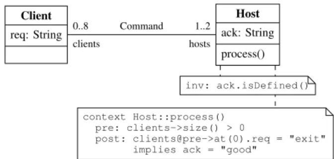
Host ack: String process() Client req: String 0..8 clients 1..2 hosts Command context Host::process() pre: clients->size() > 0
post: clients@pre->at(0).req = "exit" implies ack = "good"
inv: ack.isDefined()
Fig. 1. UML class diagram
II. PRELIMINARIES
To keep the paper self contained, definitions used in the remainder of this paper are detailed in this section. First, the notion of different UML concepts and diagram types is introduced. Then, the satisfiability problem is reviewed in Section II-B.
A. UML Models and OCL Expressions
In the most recent version of the UML standard, several concepts and respective diagram types are provided. However, in this paper we focus on three diagram types, namely the
class diagram, theobject diagram, and thesequence diagram. A class diagram comprises a UML model, which can be used e.g. to describe the structure of a system. An instantiation of a UML model is called asystem stateand is visualized by an object diagram. A system state provides a static view on the model. In addition, a sequence diagram provides the dynamic view on the model. It illustrates possible transitions between different system states, which can be reached by invoking the operations specified in the UML model.
Definition 1 (Class Diagrams): The main constructs in a class diagram are classesandattributes. Classes describe the kind of information in a system and how this information is structured. Attributes define the single data elements out of which a class is composed. Besides attributes, a class can contain operations, which process the information by usually modifying the values of the attributes. Classes can be con-nected usingassociationsto describe a relation between them. Each class connected to the association is called association-end, and each association-end is annotated with a role-name
and amultiplicity. The multiplicities classify the relation, e.g. a 1-to-1, a1-to-many, or a many-to-many relation.
Example 1: A UML class diagram is depicted in Fig. 1. It consists of the classes Client and Host. Each class consists of one attribute,req (request) andack (acknowledge), respec-tively, which can be assigned a string value. Further, the class
Host contains the operationprocess.
Both classes are related by an association calledCommand. Given its multiplicities, this association establishes that each host is connected to at most eight clients, and that each client has to be connected to at least one, but at most two hosts.
Definition 2 (OCL expressions): Using OCL expressions, textual constraints as invariants as well as pre- and post-conditions can be added to a class diagram. Invariants restrict the set of valid system states by enforcing specific system properties. On the other hand, pre- and post-conditions can be added to an operation to constrain the circumstances in which it can be called and to describe the system state after the execution, respectively.
client1: Client req = “date” host: Host ack = “good” client2: Client req = “exit” Command Command
Fig. 2. UML object diagram
Example 2: In the class diagram in Fig. 1, an invariant is used to express that the attribute ack of theHost class must always be defined. Furthermore, a pre-condition requires a host to be connected to at least one client before the operation
processcan be called. After this operation has been called, it has to be assured that the attribute ack is set to “good” in case the previous command was“exit”.
Definition 3 (Object Diagrams): Object diagrams represent a concrete system state of a UML model. The main construct in an object diagram is anobject, which is an instantiation of a class given in the class diagram. The attributes of the object are determined from the class and assigned concrete values. Finally, links in an object diagram represent instantiations of an association.
Example 3: An object diagram can be seen in Fig. 2. It represents a valid system state with respect to the UML model defined by the class diagram in Fig. 1, wherebyhostis connected to two clients, i.e. client1andclient2.
Definition 4 (Sequence Diagrams): A sequence diagram models the dynamic behavior of a UML model. It expresses the invocation of operation calls by objects and, thus, model interactivity between them. Since each operation call may affect the values of the attributes in the objects as well as the links between them, each sequence diagram captures several system states.
The set OP denotes all possible operations which can be invoked in a sequence diagram, i.e. all possible operations for each instantiated object. In this work, we model sequence diagrams in which each object calls its operations by itself.
B. Boolean Satisfiability and SAT Modulo Theories
Thesatisfiability problem(SAT) is the problem of determin-ing whether there exists a satisfydetermin-ing assignment for a given function.
Definition 5 (Boolean Satisfiability): Given a function f : Bn →
B with B = {0,1}, the function f is satisfiable, if and only if there exists an assignment α ∈ Bn such that f(α) = 1. In this case, α is called a satisfying assignment. Otherwise, f isunsatisfiable. Usually, the satisfiability check is conducted on a function in conjunctive normal form. Although the SAT problem is N P-complete [14], much re-search was dedicated to the investigation of SAT solvers in the recent decades [15], [16], [17]. Thus, many hard instances of practical problems are transformed into SAT problems and afterwards solved efficiently [18]. Furthermore, researchers combined Boolean satisfiability with problem descriptions on higher levels of abstraction, for example arithmetic or bit-vector logic, resulting in a technique called SAT Modulo Theories(SMT) [19]. Instead of having the function given in its conjunctive normal form, SMT allow complex expressions e.g. composed of arithmetic operations. In [20], it has been demonstrated that problems having a more complex structure tend to be solved more efficiently when retaining the level of abstraction in the solving process.
In this work, we transform the considered problem into an
SMT instanceconsisting of bit-vector expressions calledSMT constraints. This instance is afterwards solved by an SMT solver.
TrafficLight pedLight: Boolean carLight: Boolean request: Boolean switchPedLight() switchCarLight() Button counter: Integer requesting() button 2 light 1 context requesting() pre: tl.pedLight = false post: tl.request = true
post: counter = counter@pre + 1
context switchPedLight() pre: request = true
post: pedLight != pedLight@pre post: request = false
context switchCarLight() post: carLight != carLight@pre inv: not(pedLight = true and
carLight = true)
(a) UML class diagram b1: Button counter: 0 b2: Button counter: 0 tl: TrafficLight pedLight = false carLight = true request = false (b) Initial system state
b1: Button counter: 1 b2: Button counter: 0 tl: TrafficLight pedLight = true carLight = false request = false (c) Derived system state Fig. 3. Sample scenario
III. PROBLEMFORMULATION
This section briefly illustrates the problem considered in this paper. Given a class diagram together with an initial system state, the invocation of operations leads to different sequences of operation calls and system states, respectively. Pre- and post-conditions related to each operation define the effect of operation calls employing the design by contract -approach [21]. More precisely, in order to invoke a certain operation, the respective pre-conditions have to be satisfied. Further, after an operation call, the following system state is assumed to fulfill the post-conditions of the respective operation.
However, it is not trivial to generate sequence diagrams (i.e. sequences of operation calls) confirming the correct behavior of certain corner-case scenarios. Moreover, to ensure that a desired behavior is possible (or not) with the UML model at hand is a cumbersome verification task.
Example 4: Consider the class diagram given in Fig. 3(a), which is used to illustrate possible verification tasks in the remainder of this paper. The diagram specifies a simple traffic light preemption. If the attribute carLight (pedLight) is assigned to True, cars (pedestrians) are allowed to go. Otherwise, they are supposed to wait. By the invariant in the class diagram (denoted by inv), it should be ensured that the traffic lights for both, cars and pedestrians, are never “green” at the same time. Finally, cars are allowed to pass as long as no pedestrian requests to cross the street (i.e. no pedestrian invokes therequestingoperation). This is specified in the respective pre- and post-conditions of the operations1.
Fig. 3(b) shows an initial system state.
A serious design flaw is evident in this example. In order to reach a system state where pedestrians get a “green” light, first requestinghas to be invoked (assigning request to
True). Due to the invariant,switchCarLighthas to be executed next in order to set carLight to False. Finally, the call of
switchPedLightleads to the desired system state (also depicted
1The OCL keyword @pre is referring to the value of the respective
expression before the operation call takes place.
in Fig. 3(c)). However, no further operation calls can be per-formed in this state since (1) the pre-conditions ofrequesting
and switchPedLight fail and (2) the call of switchCarLight
would lead to a system state which contradicts the invariant. Thus, the system got stuck in a deadlock situation. In order to provide a correct specification for a system to be implemented, it is essential to detect such unwanted behavior prior to the implementation.
Besides that, other important verification tasks might be:
• Are all operations reachable (i.e. is it possible to invoke
each operation at least once within a period of time)?
• Can a certain system state be generated (e.g. is it possible
to get a “green” light for the pedestrians)?
• Is the system safe (e.g. is there a sequence of operation
calls leading to a system state where both lights are “green”)?
In summary, having a class diagram along with an initial state, it is important to check whether the specified system exhibits certain behaviors. While these checks can be performed prior to the implementation of the system, often this is a manual and therefore time-consuming process – in particular for larger models. Thus, in this paper we address the following problem:
How can we automatically check whether a wanted or unwanted behavior for a given UML class dia-gram and a given initial state exists?
IV. CHECKING THECORRECTBEHAVIOR USINGSATISFIABILITYSOLVERS
In order to automatically solve verification tasks as the ones sketched in the previous section, we suggest the usage of satisfiability solvers. In the following, the proposed approach is described. The general idea is sketched first, followed by a description of the concrete encoding.
A. General Idea
To automatically check the correctness of a specification with respect to certain corner-cases or behaviors (e.g. deadlock situations and reachability of operations), all possible execu-tion scenarios (i.e. all possible sequence diagrams) have to be considered. However, due to the infinite number of such scenarios, this is obviously not feasible. Thus, we suggest an iterative approach instead, whereby the number of considered operation calls is limited by a valuek. As a result, given a class diagram, an initial system state, and the respective verification task, we check whether the desired behavior can be obtained within k steps (i.e. within k operation calls). If that is the case, a sequence diagram confirming the correct behavior can be constructed. Otherwise, the designer may increase the value ofkto solve the task considering a longer period of time. Note that in previous work considering the consistency of operation calls verification tasks fork= 1have been conducted.
However, checking the verification task with such a restric-tion is expensive. In the worst case,|OP|kpossibilities have to
be considered, whereOP is the number of possible operations to be called in a certain system state. Thus, in order to solve the problem, we make use of satisfiability solvers, for which efficient and sophisticated solving engines are available.
The main flow is shown in Fig. 4. Given the above men-tioned inputs, we construct the problem of obtaining a desired behavior within k steps as a satisfiability instance. If the resulting instance is determined satisfiable by a respective
Class Diagram Object Diagram Verification Task Depthk Satisfiability Problem Sequence Diagram unsat +1 sat
Fig. 4. General flow
solver, a valid sequence diagram demonstrating the behavior can be derived from the solution. If in contrast the instance is unsatisfiable, it has been proven that no such scenario withink steps exists.
B. Structure of the Satisfiability Instance
Given the main flow as a basis, the open question is how to encode the satisfiability problem. In the following, the proposed encoding is described by means of Example 4 from Section III. Fig. 5 shows the components, which are already available for this purpose, independently of the considered verification task. These components include
• the initial system state (denoted by σ0) including the values for all attributes,
• the k operation calls to be defined (denoted by op0, op1, . . . , opk−1∈OP), and
• the k system states (denoted by σ1, σ2, . . . , σk) derived
from the respective operation calls.
Besides these components, the OCL expressions in a class diagram have to be considered. OCL expressions appear in terms of the invariantsIas well as the pre- and post-conditions of the chosen operations. Therefore, the following syntax is applied:
Definition 6 (Evaluation of OCL expression): For a system state σand an OCL expressionϕ, the evaluation ofϕinσis denoted by σ(ϕ). Furthermore, σ(Φ) :=V
ϕ∈Φσ(ϕ)denotes the evaluation of all expressions in Φ.
Definition 7: For an operation op defined in the class dia-gram, the pre- and post-conditions of opare denoted by Cop
and Bop, respectively. Furthermore, the invariants in a class
diagram are denoted by I.
Given these definitions, the problem mentioned above can be reduced to the question of whether it is possible to choose the operation callsop0, . . . , opk−1∈OP, such that (1) all system states satisfy the invariants, (2) the respective pre- and post-conditions match with the respective system states, and (3) the considered behavior is obtained. Formally, is it possible to choose the operation calls op0, . . . , opk−1, such that
f = k ^ t=0 σt(I)∧ k−1 ^ t=0 (σt(Copt)∧σt+1(Bopt))∧τ
is satisfiable, whereby τ denotes the respective verification task to be proven. If this is the case, a sequence diagram can be obtained from the assignments to op0, op1, . . . , opk−1.
Otherwise, it has been proven that no such behavior is possible considering the given class diagram with its invariants and pre-and post-conditions.
However, in order to solve this satisfiability problem, f has to be encoded so that it can be handled by an SMT solver. In the following sections, the concrete encodings of the needed components, i.e. system states (including invariants), the selection of the operations (including the restrictions implied by the pre- and post conditions), as well as the actual verification task, are described in detail.
C. Encoding of System States and their OCL Invariants
The encoding of the system states is inspired by [9], where Boolean satisfiability has been applied in order to determine a valid system state (in terms of an object diagram) from a given class diagram. To this end, an encoding of objects (and their attribute assignments) as well as of links between them has been introduced, respectively.
Encoding 1 (Attributes): Letcbe a class in a UML model, for which the system state σt with 0 ≤ t ≤ k should be
generated. Then, for each attribute a and for each object o inσt, a bit-vectorα~oa,t∈Bdld(n)e is created. The assignment
to α~o
a,t represents the assignment to the respective attribute
of the object o in the system state σt. The value of n is
the number of possible values that the attribute a can be assigned to (including ⊥, representing the undefined value). To ensure that ~αo
a,t can only be assigned to legal values, the
constraint ~αo
a,t < bv(n) is added to the instance, whereby
bv :N0 →Bk returns the bit-vector expansion of an integer value.
Links are encoded in a similar way. Therefore, new variables~λ are introduced, whereby the bits of ~λ represent the possible links in an object diagram. The assignment to these bits defines whether a link does exist or does not exist.
Example 5: Fig. 6(a) shows the variables and the con-straints needed to encode a system state σt which is
de-rived from the class diagram introduced in Example 4. In this object diagram, one object for the class TrafficLight
and two objects for the class Button are instantiated2. A
satisfying assignment of this instance is shown in Fig. 6(b). This assignment represents the system state depicted in Fig. 6(c).
Besides the basic structure, also the additional OCL invariants have to be considered. To this end, all specified invariants have
2Note that the Boolean attributes are encoded by anα~-variable of size 2
in order to encode the Boolean valuesFalse(represented by002) andTrue (represented by012), as well as the undefined value⊥(represented by102). As a result, the constraints~α <112are added to exclude the forth possible assignment112, which does not represent a valid value.
b1: Button counter = 0 b2: Button counter = 0 tl: TrafficLight pedLight = false carLight = true request = false σ0 b1: Button counter = ? b2: Button counter = ? tl: TrafficLight pedLight = ? carLight = ? request = ? σ1 b1: Button counter = ? b2: Button counter = ? tl: TrafficLight pedLight = ? carLight = ? request = ? σk op0=? op1=? opk−1=? . . .
~ αtl pedLight,t∈B2 ~αb1counter,t∈B32 ~ αtl carLight,t∈B2 ~αb2counter,t∈B32 ~ αtlrequest,t∈B2 ~λb1light,t∈B1 ~ λtlbutton,t∈B2 ~λb2light,t∈B1 ~ αtl pedLight,t<112 ~αtlcarLight,t<112 ~ αtl request,t<112
(a) Bit-vector variables and constraints ~ αtl pedLight,t= 012 ~ αtl carLight,t= 012 ~ αtlrequest,t= 002 ~ αb1counter,t= 102 ~ αb2counter,t= 10102 ~ λtlbutton,t= 112 ~ λb1 light,t= 12 ~ λb2 light,t= 12 (b) Satisfying assignment b1: Button counter = 2 b2: Button counter = 10 tl: TrafficLight pedLight =True carLight =True request =False
(c) Derived object diagram Fig. 6. Encoding of a system state
to be encoded into a logical equivalent using the introduced variablesα~ and~λ.
Example 6: In case of the traffic light preemption, the OCL invariant
not(pedLight = true and carLight = true)
has to be considered. This can be encoded by adding the constraint
¬ ~αtlpedLight,t= 012∧~αtlcarLight,t= 012
to the instance. Therewith, the assignment from Fig. 6(b) is not satisfiable any longer and the solver has to determine another solu-tion (e.g. with ~αtlpedLight,t= 002 and~αtlcarLight,t= 012). Analogously, other OCL constraints (e.g. further logical and arithmetic expressions, collections such as sets, bags, se-quences, or ordered sets, as well as statements like forAll
andincludes) can be encoded.
D. Encoding of Operation Calls
With the encoding of the system states, the respective operation calls can be encoded. Therefore, new variables and further constraints are introduced:
Encoding 2 (Operation Calls): For each step t with 0≤t < k, a bit-vector ~ωt∈Bdld(|OP|)e is created, representing the operation call at this step. Depending on the assignment toω~t, the respective pre-conditions (for the system
state σt) and post-conditions (for the system stateσt+1) have
to be enforced. Therefore, the constraint
k−1 ^
t=0 ^
op∈OP
(~ωt= enc(op))⇒(enc(σt(Cop))∧enc(σt+1(Bop)))
is added to the instance, whereby enc(op) represents a dis-tinct binary representation of the operation op, i.e. a number from0 to|OP| −1. Further,enc(σt(Cop))(enc(σt+1(Bop)))
represents the encoding of the respective pre-condition (post-condition). The latter encoding is analogously to the encoding of the invariants outlined above. Finally, to ensure that only le-gal values can be assigned to~ωt, the constraint~ωt<bv(|OP|)
is added to the instance.
Example 7: Reconsider the traffic light example from Fig. 3(a) and the ~α-variables shown in Fig. 6(a) intro-duced to encode the respective system states. Furthermore,
let enc(requesting) = 102 be the binary encoding of the operation requesting of object b1. To encode the respective pre- and post-conditions for that operation in step t, the constraint
(~ωt= 102) ⇒ ~αtlpedLight,t= 002 (tl.pedLight = false)
∧ ~αtlrequest,t+1= 012 (tl.request = true) ∧ ~αb1
counter,t+1=α~b1counter,t+ 12
(counter = counter@pre + 1) is added to the instance.
In other words, depending on the assignment to~ωt, constraints
derived from the respective pre- and post-conditions of the considered operation are implied. Similar constraints are added for the remaining operations.
E. Encoding of the Verification Task
Finally, the desired verification task has to be encoded. This can be done in various ways depending on the respective goal. The general procedure is hereby to pre-define the respective variables in order to enforce the desired behavior. For example:
• To check whether a certain operationop∈OP is reach-able, the constraintWk−1
t=0(~ωt= enc (op))(enforcing that
in at least one stepopis called) is added to the instance.
• To check whether a certain system state can be generated, the assignments to the respective ~α-variables have to be enforced for at least one system state. In the traffic light example, to ensure that it is possible to get a “green” light for the pedestrians, the constraint Wk
t=0(~α tl
pedLight,t =
012)is added to the instance.
In combination with the encodings introduced above, a satis-fying assignment can then be determined only if the desired behavior is possible. More complex verification tasks can be defined analogously.
F. Solving the Instance
Given the encodings presented above, a satisfiability in-stance is being constructed, which can be handled by a solving engine, if respective variables and encodings are transformed into a proper format. In this paper, we applied an SMT solver using the bit-vector logic theory QF BV. The QF BV theory provides syntactical equivalences for the bit-vector operations used above.
Having the resulting instance available, the solver tries to determine an assignment to the ~ωt variables which satisfies
all constraints. If this is possible, the respective operation calls and the resulting system states (including values of attributes and links) can be obtained by the assignments to the respective~ω-,~α-, and~λ-variables. In contrast, if no satisfying assignment can be found, it has been proven that the desired behavior is not possible considering the underlying class diagram as well as the respective invariants and conditions.
V. EXPERIMENTALEVALUATION
In order to evaluate the proposed approach, all concepts introduced above have been implemented and applied to three UML models in different setups and with different verification tasks. The results of this experimental evaluation are described in the present section. The respective SMT instances were transformed to a file in the SMT-LIB format and solved with the SMT solver Boolector [22]. The experiments were carried
TABLE I CONSIDERED MODELS
Name #Cl #Attr # Assoc #Op #Pre #Post #Inv
Switch 2 4 3 4 7 25 3
Simple CPU 6 9 6 5 8 9 8
Traffic Control 3 6 1 5 13 46 7
TABLE II EXPERIMENTALRESULTS
Name Task #Obj Depth Status Run-time
Switch Reachability 25 23 sat 49.7
Switch Reachability 25 22 unsat 50.0
Switch Reachability 25 50 sat 621.7
Switch Reachability 9 103 sat 147.5
Switch Reachability 9 102 unsat 90.4
Simple CPU State Gen. 13 100 sat 1.3
Simple CPU State Gen. 13 100 unsat 0.4
Traffic Control Reachability 6 5 sat 0.0
Traffic Control Reachability 24 10 sat 1.6
Traffic Control State Gen. 9 30 unsat 0.1
Traffic Control State Gen. 9 100 unsat 0.4
out on a 2.26 GHz Intel Core2 Duo with 3 GB main memory running Linux 2.6.
Due to page limitations, the considered models are not described in detail but briefly summarized in Table I. In the columns, the name of the respective benchmarks as well as the number of classes, attributes, associations, operations, pre-conditons, post-conditions, and invariants are listed. The
Switchmodel specifies a protocol, where clients can exchange data between each other (controlled by a common host). Further, a simple CPU including a program counter, a control unit, and an arithmetic logic unit, is modeled in the benchmark denoted by Simple CPU. Finally, the Traffic Control is an extension of the traffic light example in Fig. 3(a) with a yellow phase and suitable for a crossing.
On these models (in different configurations), two verifica-tion tasks have been performed. First, it is checked whether a certain operation is reachable (referred to as Reachability). Next, it is checked whether a certain system state can be generated (referred to as State Gen.). The results are listed in Table II. In the first columns, the name and the respective verification task is given, followed by the number of objects, the depth, the result (i.e. satisfiable or unsatisfiable), and the required run-time in seconds.
As can be seen, the verification tasks can be solved within seconds, and no task needed more time than 650 seconds to complete. In the experiments, both the number of objects and the depth have been adjusted in order to evaluate the scalability of the proposed approach. Although the run-time increases as expected, verification tasks up to 100 steps can still be considered and solved with moderate computational effort.
VI. CONCLUSION
In this paper an approach has been presented that auto-matically solves verification tasks for the dynamic view of a UML class diagram including operations with pre- and post-conditions. Sequences of operation calls including their implications on successive system states have been considered. Therefore, the respective system states, operation calls, and the actual verification task have been encoded as an instance of
the satisfiability problem. The approach has been experimen-tally evaluated in a case study, which demonstrates that the considered verification tasks can be checked efficiently.
REFERENCES
[1] J. Rumbaugh, I. Jacobson, and G. Booch, Eds.,The Unified Modeling Language reference manual. Essex, UK: Addison-Wesley Longman Ltd., 1999.
[2] Y. Vanderperren, W. M¨uller, and W. Dehaene, “UML for electronic systems design: a comprehensive overview,” Design Automation for Embedded Systems, vol. 12, no. 4, pp. 261–292, 2008.
[3] G. Martin and W. M¨uller,UML for SOC Design. Secaucus, NJ, USA: Springer-Verlag New York, Inc., 2005.
[4] J. Warmer and A. Kleppe,The Object Constraint Language: Precise modeling with UML. Boston, MA, USA: Addison-Wesley Longman Publishing Co., Inc., 1999.
[5] M. Gogolla, M. Kuhlmann, and L. Hamann, “Consistency, Independence and Consequences in UML and OCL Models,” in TAP, ser. Lecture Notes in Computer Science, C. Dubois, Ed., vol. 5668. Springer, 2009, pp. 90–104.
[6] M. Gogolla, F. B¨uttner, and M. Richters, “USE: A UML-based specifi-cation environment for validating UML and OCL,”Science of Computer Programming, vol. 69, no. 1-3, pp. 27–34, 2007.
[7] M. Kyas, H. Fecher, F. S. de Boer, J. Jacob, J. Hooman, M. van der Zwaag, T. Arons, and H. Kugler, “Formalizing UML Models and OCL Constraints in PVS,”Electronic Notes in Theoretical Computer Science, vol. 115, pp. 39–47, 2005.
[8] J. Cabot, R. Claris´o, and D. Riera, “Verification of UML/OCL Class Diagrams using Constraint Programming,” Apr. 2008, pp. 73–80. [9] M. Soeken, R. Wille, M. Kuhlmann, M. Gogolla, and R. Drechsler,
“Verifying UML/OCL models using Boolean satisfiability,” inDesign, Automation and Test in Europe. IEEE Computer Society, 2010, pp. 1341–1344.
[10] A. Baruzzo and M. Comini, “Static Verification of UML Model Consis-tency,” inProc. 3rd Workshop Model Design and Validation, Oct. 2006, pp. 111–126.
[11] X. Li, Z. Liu, and J. He, “Consistency checking of UML requirements,” inICECCS. IEEE Computer Society, 2005, pp. 411–420.
[12] J. Cabot, R. Claris´o, and D. Riera, “Verifying UML/OCL Operation Con-tracts,” inIntegrated Formal Methods, ser. Lecture Notes in Computer Science, M. Leuschel and H. Wehrheim, Eds., vol. 5423. Springer, 2009, pp. 40–55.
[13] A. Biere, A. Cimatti, E. M. Clarke, and Y. Zhu, “Symbolic Model Checking without BDDs,” inTools and Algorithms for the Construction and Analysis of Systems, ser. Lecture Notes in Computer Science, R. Cleaveland, Ed., vol. 1579. Springer, 1999, pp. 193–207. [14] S. A. Cook, “The complexity of theorem-proving procedures,” in
STOC’71: Proceedings of the third annual ACM symposium on Theory of computing. New York, NY, USA: ACM, 1971, pp. 151–158. [15] M. W. Moskewicz, C. F. Madigan, Y. Zhao, L. Zhang, and S. Malik,
“Chaff: Engineering an Efficient SAT Solver,” in Design Automation Conference. ACM, 2001, pp. 530–535.
[16] E. I. Goldberg and Y. Novikov, “BerkMin: A Fast and Robust Sat-Solver,” inDesign, Automation and Test in Europe. IEEE Computer Society, 2002, pp. 142–149.
[17] N. E´en and N. S¨orensson, “An Extensible SAT-solver,” in SAT, ser. Lecture Notes in Computer Science, E. Giunchiglia and A. Tacchella, Eds., vol. 2919. Springer, 2003, pp. 502–518.
[18] M. Ganai and A. Gupta,SAT-Based Scalable Formal Verification Solu-tions (Series on Integrated Circuits and Systems). Secaucus, NJ, USA: Springer-Verlag New York, Inc., 2007.
[19] A. Armando, C. Castellini, and E. Giunchiglia, “Sat-based procedures for temporal reasoning,” in5th European Conference on Planning, ser. Lecture Notes in Computer Science, S. Biundo and M. Fox, Eds., vol. 1809. Springer, 1999, pp. 97–108.
[20] R. Wille, D. Große, M. Soeken, and R. Drechsler, “Using Higher Levels of Abstraction for Solving Optimization Problems by Boolean Satisfiability,” inIEEE Computer Society Annual Symposium on VLSI. IEEE Computer Society, 2008, pp. 411–416.
[21] R. Wieringa, “A Survey of Structured and Object-Oriented Soft-ware Specification Methods and Techniques,”ACM Computer Surveys, vol. 30, no. 4, pp. 459–527, 1998.
[22] R. Brummayer and A. Biere, “Boolector: An Efficient SMT Solver for Bit-Vectors and Arrays,” inTools and Algorithms for the Construction and Analysis of Systems, ser. Lecture Notes in Computer Science, S. Kowalewski and A. Philippou, Eds., vol. 5505. Springer, 2009, pp. 174–177.