ROBOTIC PLATFORM RABIT for CONDITION ASSESSMENT of
CONCRETE BRIDGE DECKS USING MULTIPLE
NDE TECHNOLOGIES
N. Gucunski 1, A. Maher 2, B. Basily1, H. La2, R. Lim2, H. Parvardeh2 and S.-H. Kee1 1 Department of Civil and Environmental Engineering,
Rutgers University, Piscataway, New Jersey, U.S.A. Email: [email protected] 2 Center for Advanced Infrastructure and Transportation,
Rutgers University, Piscataway, New Jersey, U.S.A
ABSTRACT - Current assessment of concrete bridge decks relies on visual inspection and use of simple nondestructive and destructive evaluations. More advanced, but still manual nondestructive evaluation (NDE) technologies provide more comprehensive assessment. Still, due to a lower speed of data collection and still not automated data analysis and inter -pretation, they are not used on a regular basis. The development and implementation of a fully autonomous robotic system for condition assessment of concrete bridge decks using multiple nondestructive evaluation (NDE) technologies is described. The system named RA -BIT (Robotics Assisted Bridge Inspection Tool) resolves issues related to the speed of data collection and analysis. The system concentrates on the characterization of internal deterio -ration and damage, in particular three most common deterio-ration types in concrete bridge decks: rebar corrosion, delamination, and concrete degradation. For those purposes, RABIT implements four NDE technologies: electrical resistivity (ER), impact echo (IE), ultrasonic surface waves (USW) and ground-penetrating radar (GPR). Because the system utilizes multiple probes or large sensor arrays for the four NDE technologies, the spatial resolution of the results is significantly improved. The technologies are used in a complementary way to enhance the overall condition assessment and certainty regarding the detected deteriora -tion. In addition, the system utilizes three high resolution cameras to image the surface of the deck for crack mapping and documentation of previous repairs, and to image larger areas of the bridge for inventory purposes. Finally, the robot’s data visualization platform facilitates an intuitive 3-dimensional presentation of the main three deterioration types and deck surface features.
Keywords: Concrete, bridge decks, corrosion, delamination NDE, automation, GPR, electri-cal resistivity, acoustics.
INTRODUCTION
Upkeep of concrete bridge decks is one of the biggest challenges for transportation agencies. The Federal Highway Administra -tion’s (FHWA’s) Long Term Bridge Perfor -mance (LTBP) Program team interviewed a number of state Departments of Transporta-tion (DOTs) regarding the expenditure lev -els for maintenance, rehabilitation, and re -placement of bridges. The conclusion of the interviews was that bridge decks constitute
between 50 and 80 percent of the overall expenditures for bridges. This high expense stems from three primary reasons. The first reason is that bridge decks, due to their di -rect exposure to traffic and environmental loads, deteriorate faster than other bridge components. The second reason is the in -spection practices that detect problems only once those have reached their last stage of progression. For example, the predominant practice of condition assessment of con-crete bridge decks in the United States is
ROBOTIC PLA
TFORM RABIT for CONDITION
ASSESSMENT of CONCRETE BRIDGE DECKS USING MUL
by visual inspection and use of simple NDE tools like chain drag and hammer sounding. While such approaches have its merits, they also have limitations in terms of the early problem detection and characterization of deterioration or defects with respect to their state of progression. The third reason is that rehabilitation practices rarely address early problem mitigation. For all these reasons, the performance of concrete bridge decks was identified as the most important bridge performance issue that needs to be ad -dressed.
The LTBP Program initiated periodical data collection on concrete bridge decks using multiple NDE technologies (Gucunski et al. 2012 and 2013). It was demonstrated dur-ing the initial phase of the program that: 1) NDE technologies can provide accurate condition assessment, 2) condition indices obtained from NDE survey results provide more objective condition assessment, and 3) NDE enables monitoring of deteriora-tion progression through periodical surveys. However, it was also recognized that such surveys require significant effort and time, and ultimately represent a significant ex -penditure. For example, a typical compre -hensive survey within the LTBP Program would require a team of five to six special -ists and technicians. To address the need for evaluation of hundreds of bridges in the next phase of the Program, the FHWA initiated in 2011 the development of a ro -botic system for the NDE of concrete bridge decks. The main goal of the development was to improve both the data collection and data analysis components. On the data col -lection side the concentration was on an in -crease of speed of data collection and its automation. On the data analysis side, the concentration was on its automation and the enhancement of the current data inter -pretation and presentation. During the first two years of the development, many of the stated objectives were achieved and RABIT is being deployed on a regular basis.
The paper provides an overview of current NDE of concrete bridge decks and their
evaluation using RABIT system. The first part of the paper concentrates on the de -scription of typical deterioration in concrete bridge decks. In the second part, a descrip -tion of the current practice of NDE of bridge decks, with the concentration on the NDE methods implemented in RABIT. Finally, the third part provides a description of the phys -ical components of the robotic system and their operation. The data collection process, and data analysis and presentation/visuali -zation are presented by sample results.
CONCRETE DECK DETERIORATION
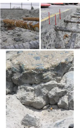
Deterioration in concrete bridge decks can be caused by a number of causes of chemi -cal, physical and even biological nature. Because of it, different NDE technologies will be more effective in their detection and characterization. The most common cause of deterioration is corrosion that will typically lead to concrete delamination and spalling, as shown in Figure 1.
Figure 1 Typical concrete bridge deck deterio-ration and damage: rebar corrosion (left), de-lamination (middle), and deck spalling (right).
ROBOTIC PLA
TFORM RABIT for CONDITION
ASSESSMENT of CONCRETE BRIDGE DECKS USING MUL
ROBOTIC PLA
TFORM RABIT for CONDITION
ASSESSMENT of CONCRETE BRIDGE DECKS USING MUL
TIPLE NDE TECHNOLOGIES
It should be also mentioned that delamina -tion can be induced by repeated overload -ing and fatigue of concrete (Gucunski et al. 2013). Corrosion and delamination are also the deterioration types of the highest interest to bridge owners, since the most of the repairs are related to those. However, some other deteriorations (e.g. alkali-silica reaction, delayed ettringite formation, car -bonation), will primarily cause
material alterations, in terms of a reduced elastic modulus or strength, or changed electrical and chemical properties. Dete -rioration of bridge decks is often accelerated by the lack of main -tenance, or use of improper pro-cedures during their construc -tion, especially during concrete curing. Therefore, information obtained from the data collected using multiple NDE technologies will be necessary to identify the primary causes of deterioration.
CURRENT PRACTICE OF NDE OF BRIDGE DECKS
Today, NDE technologies are most common -ly used to assess whether a deck requires and what type rehabilitation, or to identify areas that should be rehabilitated/repaired. However, for effective bridge management, bridge owners should develop strategies regarding the selection of NDE technolo -gies. Such strategies should enable captur -ing deterioration in concrete bridge decks at all stages of their development. For ex -ample, in a case where deterioration is pri -marily caused by corrosion, the process can be described as the one initiated by the de -velopment of a corrosive environment. One of the ways to detect and characterize cor -rosive environment is by using a electrical resistivity (ER) measurement. As the corro -sive environment becomes more severe, it will initiate corrosion activity in rebars. Fur -thermore, rebar corrosion will induce micro and macro cracking of concrete. This will be manifested in delamination of the deck, which can be detected and
characterized using impact echo (IE). It will also be reflected in the reduction of concrete elastic properties, which can be measured using the ultrasonic surface waves (USW) method. Implementation of the mentioned and additional NDE technologies is illus -trated in Figure 2, where measurements by all are being taken on a 0.6 m by 0.6 m test grid.
Figure 2 Most commonly used NDE technologies in detection of corrosion induced deterioration.
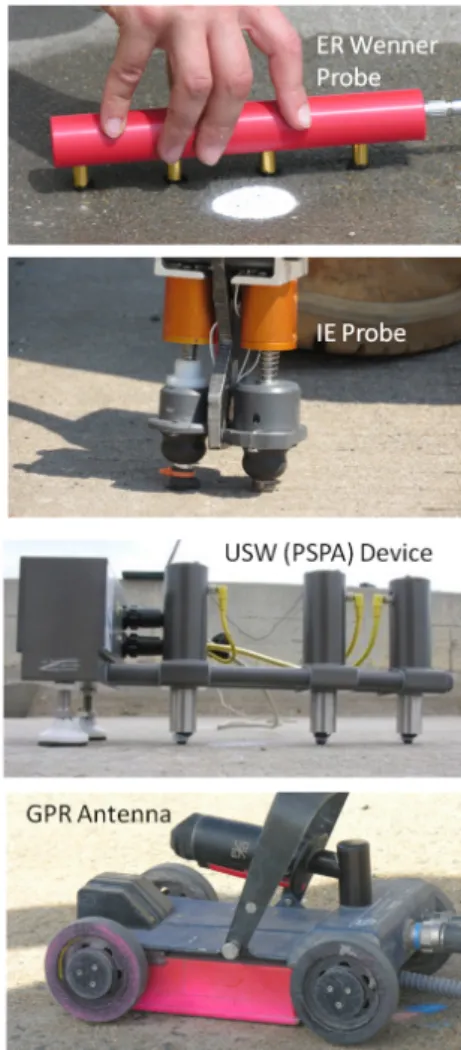
Figure 3 Samples of probes and devices of NDE technologies implemented in RABIT.
ROBOTIC PLA
TFORM RABIT for CONDITION
ASSESSMENT of CONCRETE BRIDGE DECKS USING MUL
TIPLE NDE TECHNOLOGIES
Manual equivalents of the probes and de -vices of NDE technologies implemented in RABIT are shown in Figure 3. Electrical resistivity is a descriptor of corrosive envi -ronment. Dry concrete will pose a high re -sistance to the passage of current, and thus will be enable to support ionic flow. On the other hand, presence of water and chlorides in concrete, and increased porosity due to damage and cracks, will increase ion flow, and thus reduce resistivity. Resistivity is typically measured using a four electrode Wenner probe, shown in the figure. The two outer probes are used to induce the current into concrete, while the inner two to meas -ure the potential of the generated electrical field. From the two the electrical resistivity of concrete is calculated (Brown 1980). An impact echo (IE) probe consists of a me -chanical impactor and a receiver. When an impact is applied, bridge deck resonances will be induced. The resonances represent “reflections” from the bottom of the deck or delamination, or flexural oscillations of the delaminated part of the deck (Sansalone, 1993).
Concrete modulus is measured using the USW method by devices similar to the one in the figure, called portable seismic prop -erty analyzer (PSPA) (Nazarian et al. 1993). The device has a single impact source and at least two receivers that measure the velocity of surface waves (phase ve -locity) generated by an impact. The phase velocity profile is used to assess the aver -age concrete modulus or modulus profile. Qualitative assessment of concrete deck can be made using ground penetrating ra-dar (GPR). Electromagnetic waves gener-ated by an emitting antenna are in part be -ing reflected from the objects and interfaces of materials of different dielectric properties and detected by a receiving antenna. The strength of the reflection from the top rebar, which is typically described as the attenu -ation of the signal, is used to characterize corrosive environment and possible delami-nation (Barnes and Trottier 2000). The at -tenuation of the GPR signal is primarily af -fected by the changes in concrete
conductivity and dielectric value. Concrete filled with moisture and chlorides is highly conductive and causes strong wave attenu-ation. Therefore, the GPR assessment of -ten provides a good description of corrosive environment. In addition, GPR surveys en -able rebar mapping and the measurement of concrete cover, which in some cases may point insufficient and variable cover as a contributing factor to accelerated deteriora-tion.
BRIDGE DECK INSPECTION USING RABIT
Description of Physical Components and Data Collection
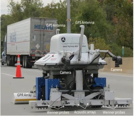
The robotic system with its main NDE and navigation components marked is shown in Figure 4. On the RABIT’s front end there are two acoustic arrays of the total width of 1.8 m, which matches the scanning width of the system. Each acoustic array contains four impact sources and seven receivers. They are used in different combinations to enable multiple impact echo and USW measure -ments. In particular, RABIT’s acoustic ar -rays can be considered to be equivalent to fourteen IE and eight or more USW devices. This large number of sources and receivers facilitates IE data collection at about 15 cm spatial resolution, and USW concrete mod -ulus measurements at a 25 cm resolution in the robot’s transverse direction. This is a much higher spatial resolution than a previ -ously described 60 cm resolution commonly used in deck testing, and identified in the current LTBP Program protocols for data collection. The resolution in the direction of the robot movement can be controlled by the robot movement and sampling. Four Proceq Resipod electrical resistivity (Wen -ner) probes are attached on the front side of the acoustic arrays. To establish electri -cal contacts between the deck surface and probes, the probe electrodes are being con -tinuously moistened using a spraying sys -tem. There are two high resolution cameras that are being used to capture the
ROBOTIC PLA
TFORM RABIT for CONDITION
ASSESSMENT of CONCRETE BRIDGE DECKS USING MUL
TIPLE NDE TECHNOLOGIES
deck surface for mapping of cracks, spalls, previous repairs and other surface anoma -lies. Each of the cameras, once the images are stitched, covers approximately a 60 by 90 cm area.
Figure 4 Front end of RABIT with NDE and nav-igation components.
Two IDS (Italy) Hi-Bright GPR arrays are at -tached on the rear side of the deployment mechanism (Figure 4). Each of the arrays has sixteen antennas, or two sets of eight antennas with dual polarization. The third camera (not visible in the figure) is placed on a pneumatic mast in the middle of the robot that can lift the camera up to a 4.5 m height. The camera has a 360 degree mirror that enables panoramic images of the sur -rounding of the tested area.
The robot’s movement can be controlled using a keyboard, joystick, Android type de -vice, or even Iphone. For a fully autono -mous movement, the robot uses three sys -tems or devices. The primary navigation system is a differential GPS, for which the robot uses two Novatel antennas mounted on the robot, and the third one on a tripod, the base station. In addition, RABIT has on board inertial measurement unit (IMU) and a wheel encoder. The information from the
three systems is fused using a Kalman fil -ter to facilitate movement with an accuracy of about 5 cm. High agility of the robotic platform is enabled by four omni-direction -al wheels, which -allow the robot to move
laterally and to turn at a zero ra -dius. These wheels also allow fast movement from one test location to the next one in any direction. With all the NDE sensors fully de -ployed, the robot is about 2.1 m long and 1.8 m wide.
The survey is conducted by mul -tiple sweeps of the robot in the longitudinal bridge direction. Each sweep covers a 1.8 m wide strip, equivalent to one half width of a typical traffic lane 3.6 m wide. At the end of a strip, RABIT trans -lates to the next strip and rotates 180 degrees before proceeding with another sweep. The survey starts with taking of the GPS co -ordinates of the GPS base station. This needs to be done only once for a particular bridge. Afterwards, the data collection path can be fully defined by taking GPS coordi -nates at three arbitrarily selected points on the bridge deck.
The data collection is fully autonomous. It can be done in either the full data collection mode, or the scanning mode. In the full data collection mode, the robot moves and stops at prescribed increments, typically 30 to 60 cm, and deploys the sensor arrays to collect the data. In the scanning mode, the system moves continuously and collects data using only the GPR arrays and digital surface im -aging.
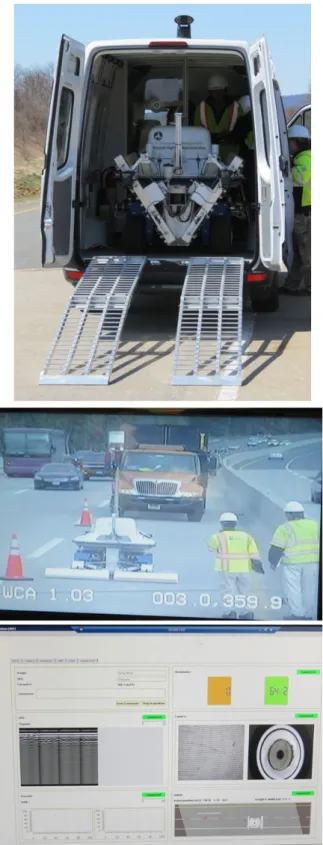
The data from the sensor arrays and probes, and digital cameras are wirelessly transmit -ted to the “command van” shown in Figure 5. RABIT can collect data on approximately 300 m2 of a bridge deck area per hour. In the continuous mode, the production rate is more than 1,000 m2 per hour.
ROBOTIC PLA
TFORM RABIT for CONDITION
ASSESSMENT of CONCRETE BRIDGE DECKS USING MUL
TIPLE NDE TECHNOLOGIES
Figure 5 Command van and data collection and robot monitoring displays.
The data collection process can be moni -tored in real time in the command van, as illustrated in Figure 5. Four main displays are used for that purpose, as well as for the display of real time, or near real time, con -struction of condition maps for some NDE technologies and stitched deck surface im -ages. The summary of all the functions that can be displayed, or will be available in the near future, on the four monitors are listed in Table 1. In addition, two smaller displays enable monitoring of the robot movement and survey progression.
Table 1 Display Functions in the Command Van
Data Analysis, Interpretation and Visualization
The most important results of RABIT sur -veys are condition maps. An example of those are a delamination map from impact echo and concrete modulus map from USW (Figure 6).
Figure 6 Delamination map (top) and concrete modulus map (bottom).
ROBOTIC PLA
TFORM RABIT for CONDITION
ASSESSMENT of CONCRETE BRIDGE DECKS USING MUL
TIPLE NDE TECHNOLOGIES
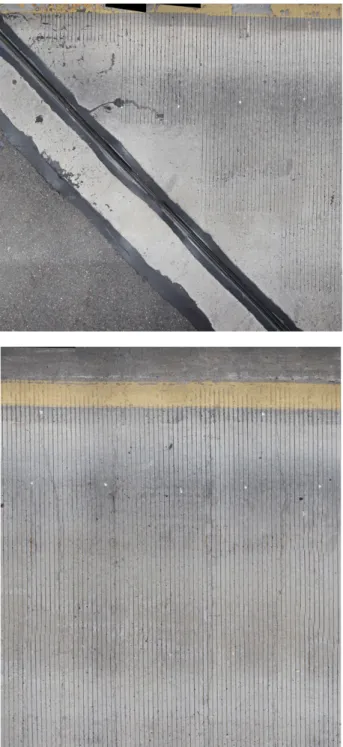
In addition, collected deck surface im-ages are stitched into a single or multiple large high resolution images of the bridge deck. The images are imported into an im -age viewer that allows review at different zoom levels, and identification of position and dimensions of identified features. Two high resolution images of two sections of the bridge are shown in Figure 7, the left one showing a joint, the second transverse cracking of the deck. Finally, a 3D visualiza -tion platform enables integra-tion and
Figure 7 High resolution images of the deck surface.
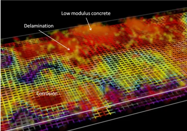
visualization of the NDE results and images in an intuitive way. The main internal dete -rioration types: corrosion, delamination, and concrete degradation (low quality concrete), and the deck surface defects are presented in a common 3D space. This data presenta -tion is illustrated in Figure 8. Zones of low concrete modulus concrete are described as clouds of different translucencies and color intensity. On the other hand, delaminations are presented as predominantly horizon -tal thin clouds at the depth and position as detected by the IE test. The severity of de -lamination is presented through the varia -tion of translucency and color of the image. Similarly, the corrosive environment is dis -played through coloring of the rebars. Hot colors (reds and yellows) are an indication of highly corrosive environment and, thus, expected high corrosion rates, while cold colors (blues and greens) are an indication of low corrosive environment and, thus, low corrosion rates. Finally, the surface of this 3D deck volume, not shown in the figure, is overlaid by a high-resolution image of the deck surface, as those shown in Figure 7.
CONCLUSIONS
Implementation of NDE in condition assess-ment of bridge deck will be essential for ef-fective management of bridges. RABIT with its integrated multiple NDE technologies and vision, fully autonomous and rapid data collection, and near real time data analysis and interpretation, overcomes the past ob -stacles related to slow data collection and interpretation. In addition, rapid and fully autonomous data collection will significantly reduce the required workforce and expo -sure of the bridge inspection crews to the passing traffic. It will also in long term re -duce costs of comprehensive bridge decks inspections, and make the assessment of a large population of bridges feasible.
ROBOTIC PLA
TFORM RABIT for CONDITION
ASSESSMENT of CONCRETE BRIDGE DECKS USING MUL
TIPLE NDE TECHNOLOGIES
ACKNOWLEDGMENTS
RABIT was developed under DTFH61-08-C-00005 contract from the U.S. Depart -ment of Transportation – Federal Highway Administration (USDOT-FHWA). The au -thors gratefully acknowledge contributions of: Professors Jingang Yi and Kristin Dana, and former graduate students Parneet Kaur and Prateek Prasanna.
REFERENCES
[1] Barnes, L. and Trottier, J.-F. (2000). “Ground penetrating radar for network level concrete deck repair management”, Jour -nal of Transportation Engineering, ASCE, 126(3), 257-262.
[2] Brown, R. D. (1980). “Mechanisms of corrosion of steel in concrete in relation to design, inspection, and repair of offshore and coastal structures”, ACI SP-65: Perfor -mance of Concrete in Marine Environments, 169-204.
[3] G ucunski, N., Romero, F., Imani, A. and Fetrat, F.A. (2013). “Nondestructive
evaluation-based assessment of deteriora-tion progression in concrete bridge decks”, Proceedings of 92nd Annual Transportation Board Meeting, Washington, D.C., January 13-17, on CD.
[4] Gucunski, N., Maher, A., Ghasemi, H. and Ibrahim, F. (2012). “Segmentation and condition rating of concrete bridge decks us-ing NDE for more objective inspection and rehabilitation planning”, Proceedings of 6th Intl. Conference on Bridge Maintenance, Safety and Management-IABMAS 2012. Stresa, Lake Maggiore, Italy, July 8-12, on CD.
[5] Nazarian, S., Baker, M.R. and Crain, K. (1993). Development and Testing of a Seismic Pavement Analyzer. Report SHRP-H-375, Strategic Highway Research Pro -gram, NRC, Washington, D.C.
[6] Sansalone, M. J. (1993). “Detecting de -laminations in concrete bridge decks with and without asphalt overlays using an au -tomated impact-echo field system”, NDT in Civil Engineering, Proceedings of Intl. Con-ference of British Institute of Non-Destruc -tive Testing, Liverpool, U.K., April 14-16, 807-820.
Figure 8 3D visualization of the detected deterioration and defects.