LWT-CLAHE Based Color Image Enhancement Technique: An
Improved Design
Oluwakemi Marufat Gazal*, Adewale Emmanuel Adedokun, Imeh Jarlath. Umoh, Muyideen Omuya Momoh
Department of Computer Engineering Ahmadu Bello University, Nigeria
Zaria, Nigeria *[email protected]
ABSTRACT
Color image enhancement is one of important process and actually a vital precursory stage to other stages in the field of digital image processing. This is d u e to th e f act that the effectiveness of processes in this stage on the output determ ines the success of other stages for a quality overall performance. This paper presents a colo r im age enhancement technique using lifting wavelet transform (LWT) and contrast limited adaptive histogram equalization (CLAHE) to overcome the issue of noise amplification, over and under-enhancement in exiting enhancement techniques. Test images from Computer Vision Database were used for the proposed tech niq ue an d the performance was evaluated using PSNR and SSIM. Result obtained shows an average improvement of 56.4% and 20.98% in terms of PSNR and SSIM respectively.
Keywords: Color Image, Enhancement, LWT, CLAHE, HSV, PSNR, SSIM.
1. INTRODUCTION
Image enhancement can be defined as the process of manipulating an input digital image such that the resulting output is more suitable for a specific task [1]. The task may be for more appealing visual appearance or to prepare it to be suitab le for further analysis. Image enhancement techniques are common ly used in areas such as satellite imaging, Medical Imaging (Computerized Tomography (CT) Scan s and Magnetic Resonance Imaging (MRI)), Remote observation and sensing, Subaquatic Imaging, Forensic, Digital Camera Applications, among others [2].
Enhancement of image can be done both in the spatial and f req uency d omain. Enhancement techniques in the spatial domain involves direct manipulation of pix el values based on their topological arrangement and neighborhood this includes global histogram equalization and its different variance and contrast stretching. Spatial domain techniques are usually characterized by inherent noise amplificatio n, o v er - or under-enhancement, color distortion [3] and sometimes unnatural appearan ce o f the resulting output [4]. However, frequency domain techniques are able to avoid some of these limitations due to their characteristics to distinguish image pix el in to smooth and detail region of the image [5] and this can then be enhanced accordingly. There are different techniques used in the frequency domain, this includ es d iscrete cosine transform (DCT), Dual Tree-Complex wavelet (DT-CW), Discrete wavelet Transform (DWT), Fast Fourier Transform (FFT), Lifting wavelet Transform
Oluwakemi Marufat Gazal, Adewale Emmanuel Adedokun, Imeh Jarlath. Umoh, Muyideen Omuya Momoh LWT-CLAHE Based Color Image Enhancement Technique: An Improved Design (LWT) nonetheless these methods may cause blurriness in the resulting output image and noise emphasis towards the edges [6].
2. RELATEDWORKS
There has been several techniques and combination of techniques used for image enhancement but most of it suffers from either over or under-enhancement and most especially noise amplification which prevent the enhanced image to sufficiently perform the intended task. In [7] the authors introduced an image enhancement method for satellite low contrast color image using Discrete Wavelet Transform (DWT) to decompose the input image into four different sub bands namely Low -Low (LL), -Low-High (LH), High--Low(HL) and High-High(HH). This was do n e o n each of the three-color spectrum of the input low contrast image (ie RED-, Blue- and GREEN-spectrum of the RGB) separately. The LL sub band of each of the color specs is then decomposed into series of binary levels, each of which was p ro cessed separately. The method was able to remove blurriness in the image however, the resulting image details was not effectively highlighted and noise amplificatio n was observed towards the edges.
Authors in [3] combined spatial- and frequency-domain technique to elim in ate the contrast over-stretching and noise amplification problem of spatial domain technique by enhancing only the low frequency component of the image by CLAHE previously split by DWT and introduced a weighted average of the original and enhanced image using a predefined weighting factor to adaptively control the enhancement level of regions with different luminance to get the fin al o u tp u t. Th e technique was tested only on grayscale images although it succeeded in bring out details in a low contrast image, however the details were not efficiently enhanced as some details in the image are lost to blurriness and suffers from noise amplification. Satellite image enhancement using single value decomposition was proposed in [8], the image was first equalized using GHE and simultaneously decomp osed in to four sub-bands using DWT, the equalized image was later decomposed also. The singular value matrix was estimated for the two LL sub -bands (the equalized and non-equalized and the SVD values are used to calculate the new LL su b -b and , th is new LL is added to the equalized high frequency components and the inverse is taken to reconstruct the enhanced image. However, the resulting output suffers fro m noise amplification.
A color image enhancement technique was proposed in [9] using Lap lacian filter and CLAHE. They converted the input image to HSV and the S and V components are filtered using Laplacian, output from this was used to calculate local correlation, variance and luminance to get an enhanced V component which is further enhanced using CLAHE, the Laplacian Filtered S component was further enhanced by stretching using a fixed stretching factor value of 0.77, the final im age is then obtain by converting the combination of the H, enhanced S and V components back to RGB. Then, [10] proposed an enhancemen t tech niq ue wh ich decomposes the input image into low and high frequency using LWT an d en h an ce
test images and several performance metrics like the AMBE, Average in f o rmatio n content, contrast improvement index, degree of entropy unpreserved, SSIM and universal quality index was used to evaluate the result obtained and compared with some exiting technique like GHE, BBHE, DSIHE, MMBEBHE, DQHEPL, BHEPLD, NPMHE and CLAHE. The result obtained was observed to outperform all of these techniques on most of the metrics except the CLAHE with wh ich it h as comparable results. Although this technique is robust considering it high performance in all the metrics used however, it only focuses on the im age co n trast and no consideration was given to image details which needs special focus to efficiently enhance an image. Also, the weighting factor process will further add noise to the enhanced image. To efficiently enhance an image the improv ed d esign LWT-CLAHE based technique is proposed where different image co mpo nents are distinct and enhanced independently to avoid over-enhanced and effectively eliminate inherent noise.
3. PROPOSED TECHNIQUE
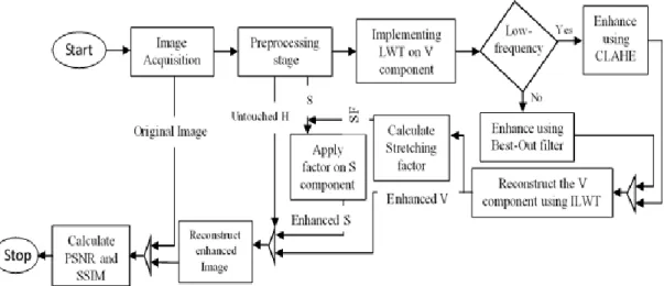
The proposed technique of color image enhancement using LWT and CLAHE is made up three main stages namely; the pre-processing stage where image where separation of image into color, color intensity and luminance using HSV model and noise removal from the S and V occurs, secondly the detail enhancemen t stage where the V component is converted to transform domain using LWT an d th e low and high-frequency is enhanced using CLAHE and developed best-out filter and the last stage involves the contrast enhancement where a stretching factor is calculated and applied on the S component. Figure 1 shows the flow chart of the proposed technique.
Oluwakemi Marufat Gazal, Adewale Emmanuel Adedokun, Imeh Jarlath. Umoh, Muyideen Omuya Momoh LWT-CLAHE Based Color Image Enhancement Technique: An Improved Design 3.1 PRE-PROCESSING STAGE
The input image used in the experiment are standard test images obtained from the computer Vision Database [11]. The input image was converted from its original color format of RGB to HSV so as to effectively separate the color, color intensity and luminance content of the image before enhancement. The S and V component are filtered using median filter to reduce the inherent noise the image must have acquired during acquisition. This denoised com ponents then serves as input to the succeeding stages. The formula for converting RGB to HSV is giv en in equations (1 to 6).
Value (V) =Value = max(R, G, B) (1) Det = Value – min(R, G, B) (2)
Saturation = Det /Value (3)
If R = Value, Hue(H) = 1/6((G – B)/Det) (4) G=Value, Hue(H ) = 1/6 (2 +(B – R)/Det) (5) B=Value, Hue(H) = 1/6 (4 + (R – G)/Det) (6)
where R, G, B is the Red, Green and Blue channel.respectively.
3.2 IMAGE DETAILS ENHANCEMENT
Structures that make up the outline of details in an image are mostly presented in the luminance (V) component of the HSV model. In order to m ak e th e details in the image more pronounced and highlighted the V component has to be effectively enhanced. The LWT, CLAHE and Best-out filter is employed to enhance the image details.
3.3 LWT-CLAHE IMPLEMENTATION
The de-noised V component is transformed into transform domain using LWT. The LWT computational complexity is more effective and speed is faster [12] unlike other transform or frequency domain techniques in enhancement which suffer from computational complexity and expenses(memory) [13], due to the issue of optimal parameters selection [14]. LWT transform parameters (coefficients) are integers which eliminate quantization error that arise from other wavelet transforms.
image. The high-frequency is subjected to the best-out filter. The image details enhancement procedure is given as follows;
Step 1: Decomposed the de-noised V component by 2-level LWT using haar wavelet into low- and high-frequency components
Step 2: Enhance the low-frequency component using CLAHE
Step 3: Enhance the high-frequency component using the developed Best-out filter. Step 4: Inverse transform the enhanced low- and high-frequency using ILWT to obtain the enhanced V component (𝑉𝑒𝑛ℎ).
3.4 CONTRAST LIMITED ADAPTIVE HISTOGRAM EQUALIZATION Since its introduction in 2013, CLAHE has proven to be an effectiv e image local details enhancement technique as stated earlier. There are two important parameters that needs to be defined when using CLAHE. The parameters are the block size to choose the contextual region to avoid over or under-enhancemen t an d clip limit to reduce noise amplification. The whole image is divided into sub -image of non-overlapping contextual region based on the block size while over enhancement is controlled using the clip limit. In this paper a block size o f 3 X3 to ensure close region equalization and clip limit of 0.01 (to reduce amplification of noise to the barest minimum) is predefined. The procedural step in im plementing CLAHE on the low-frequency component of V is given in Figure 2.
Oluwakemi Marufat Gazal, Adewale Emmanuel Adedokun, Imeh Jarlath. Umoh, Muyideen Omuya Momoh LWT-CLAHE Based Color Image Enhancement Technique: An Improved Design 3.5 BEST-OUT FILTER
Due to the sensitivity of noise in the image which in most cases is more pronounced in the detail part of the image (high frequency), a filter is dev elo ped to manipulate the pixel values but only keep the changes only if the new value is better than the original. This filter circumvents amplification of noise in the noisy parts and enable enhancement in the less noisy or noise-free part. The images considered here are assumed to be 8-bits and the highest intensity level considered is 255. The procedure of the best-out filter is highlighted as follows;
Step 1: Import the high-frequency (HF) component of the transformed V component Step 2: Find the size of HF component in rows and column, store as r and c
Step 3: Calculate probability density function (pdf) of each value of the HF component and store in an array.
Step 4: Calculate cumulative density function (cdf) of each of the PDF v alu e f ro m step 3
Step 5: Calculate modified CDF by multiplying each CDF value from step 4 b y th e highest intensity level in the image (256), add 0.5 and round up to the nearest integer Step 6: Perform conventional Histogram equalization on the values from step 5 Step 7: Compare each of the original image pixel values with the results from step 6 and keep the best of the two.
3.6 CONTRAST ENHANCEMENT
The enhanced V component is used to calculate the stretching factor to be applied on the contrast of the image. This is calculated adaptively (to elimin ate th e problem of over- or under-stretching) by histogram analysis of V and intro du cin g a weighted function. The stretching factor (sf) formula is given by below;
𝑠𝑡𝑟𝑒𝑡𝑐ℎ𝑖𝑛𝑔 𝑓𝑎𝑐𝑡𝑜𝑟 = 1 − 𝑐𝑑𝑓𝑤 (7) where 𝑐𝑑𝑓𝑤 is the weighted cdf from the histogram analysis which is dep end ent o n the 𝑝𝑑𝑓𝑤 by the equation i and ii;
𝑐𝑑𝑓𝑤(𝑖) = ∑ ( 𝑝𝑑𝑓𝑤(𝑖) ∑ 𝑝𝑑𝑓𝑤) 𝑖𝑚𝑎𝑥 𝑖=0 (8) 𝑝𝑑𝑓𝑤(𝑖) = 𝑝𝑑𝑓𝑚𝑎𝑥( 𝑝𝑑𝑓(𝑖)−𝑝𝑑𝑓𝑚𝑖𝑛 𝑝𝑑𝑓𝑚𝑎𝑥−𝑝𝑑𝑓𝑚𝑖𝑛) 𝛼 (9)
The enhanced contrast is calculated using the stretching factor as given in equation below;
𝑆𝑒𝑛ℎ= 𝑆𝑑𝑠𝑡𝑟𝑒𝑡𝑐ℎ𝑖𝑛𝑔 𝑓𝑎𝑐𝑡𝑜𝑟 (10) where 𝑆𝑒𝑛ℎ is the enhanced S and 𝑆𝑑 is denoised S.
The enhanced V (𝑉𝑒𝑛ℎ) and S (𝑆𝑒𝑛ℎ) components are added to the unaltered H and converted back to RGB to get the final enhanced image.
4. EXPERIMENTAL RESULTS AND DISCUSSION
The proposed algorithm was implemented in MATLAB 2018a and executed on a computer with Intel® Core(TM) i5-7500 CPU @3.40GHz processor with a 8Gb RAM 64-bits Operating system. Standard color test mages used for the developed algorithm were obtained from Computer Vision Database and the results obtained are evaluated using Peak Signal-to-Noise Ratio (PSNR) and structural similarity index (SSIM) given by the following formula.
(11) where maxIntensity is the maximum intensity level in the image which is 2 5 5 f or a 8-bits image and MSE is the mean square error given as;
(12) here r, c is the number row and column in the image respectively, is the output image and is the input image.
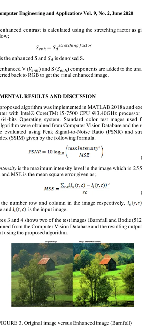
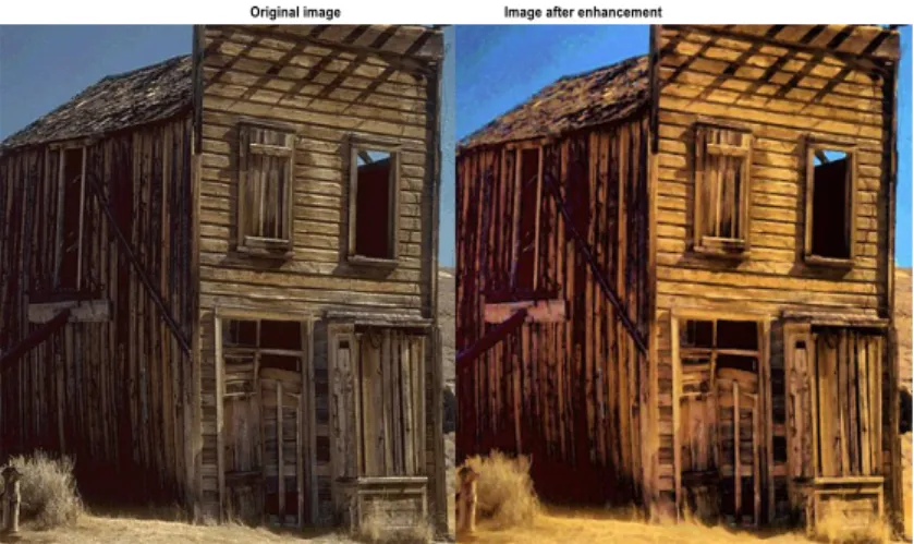
Figures 3 and 4 shows two of the test images (Barnfall and Bodie (512 X 512 pixels)) obtained from the Computer Vision Database and the resulting outputs after enhancement using the proposed algorithm.
Oluwakemi Marufat Gazal, Adewale Emmanuel Adedokun, Imeh Jarlath. Umoh, Muyideen Omuya Momoh LWT-CLAHE Based Color Image Enhancement Technique: An Improved Design
FIGURE 4. Original image versus Enhanced image (Bodie)
In Figure 3 the effective image details enhancement can be observed from the variation of color intensity of green grasses in different area, th e ro o fin g sh eet rusty color and clearer presentation of details of wire fence at the bottom of the image this can also be observed in Figure 4 on clearer appearance of d etails o f th e whole plank house frame, the dimension of the planks use for support of the window by the side and blue color intensity of the sky.
Generally, it can be observed that both the image details as well as the intensity of colors in the image were effectively enhanced using the proposed algorithm and natural visual appearance is retained. It can also be observed th at th e inherent noise perceived in the original image is less conspicuous in th e en h an ced image.
The result obtained for PSNR and SSIM using different test images from Computer Vision Database is compared with the work of [9] where the authors used Laplacian filter to enhance V component and fixed value 0.77 of gamma for co ntrast stretching unlike the proposed algorithm where the contrast of the image is adaptively stretched based on the image luminance composition. Tables 1 and 2 presents the PSNR and SSIM results respectively. From table 1 and 2, it can be observed that the images are enhanced better than the Laplacian-CLAHE algo rith m and also image structure are better preserved.
TABLE 1.
Comparison of PNSM Values of Test Images
Sn Image Na me PSNR of proposed a lgorithm (dB) PSNR of La placian +CLAHE (dB) Improvement (%) 1 Ba rnfall 76.2062 29.3227 61.52 2 Bodie 66.1031 30.7823 53.43 3 Butterfly 66.4998 28.3227 57.41 4 Clinmill 72.1240 29.5946 58.97 5 Flower 84.8102 29.6242 65.07 6 Tulips 57.6032 27.5110 52.24 7 Voit 57.4301 28.3812 50.58 8 Peppers 62.4275 29.9763 51.98 TABLE 2.
Comparison of SSIM Values of Test Images
Sn Image Na me PSNR of proposed a lgorithm (dB) PSNR of La placian +CLAHE (dB) Improvement (%) 1 Ba rnfall 0.6628 0.5219 21.26 2 Bodie 0.8164 0.5677 30.46 3 Butterfly 0.7840 0.6636 15.36 4 Clinmill 0.6690 0.6311 5.67 5 Flower 0.8408 0.5466 34.99 6 Tulips 0.7105 0.4976 29.96 7 Voit 0.8519 0.7245 14.95 8 Peppers 0.8558 0.7261 15.15 5. CONCLUSION
This paper presented an improved design of LWT-CLAHE image enhancement technique. The technique enhances image details an d co n trast wh ile reducing noise amplification and retain its natural appearance to overcome issu e o f under and over enhancement associated with conventional techniques. The o rigi n al color image is converted to HSV, the luminance (V) component was decomposed to transform domain to separate the low- and high frequency using LWT and enhanced independently. The lowfrequency is then enhanced using CLAHE and high -frequency using Best-out filter. The contrast or color intensity is adaptively enhanced by a stretching factor calculated using the enhanced luminance. The enhanced luminance and contrast are then combined with the unaltered color content (Hue) and converted from HSV to RGB to obtain the final output. The result of proposed algorithm is evaluated using PSNR and SSIM.
REFERENCES
[1] R. Dorothy, J. R M, J. Rathish, S. Prabha, S. Rajendran, and S. Joseph, “Image enhancement by Histogram equalizationNo Title,” Int. J. Nano
Oluwakemi Marufat Gazal, Adewale Emmanuel Adedokun, Imeh Jarlath. Umoh, Muyideen Omuya Momoh LWT-CLAHE Based Color Image Enhancement Technique: An Improved Design
Corros. Sci. Eng., pp. 21–30, 2015.
[2] R. C. Gonzalez and R. E. Woods, Digital Image Processing, 3rd Editio ., n o. September. Pearson Prentice Hall Pearson Education, Inc. Upper Saddle River, New Jersey 07458, 2008.
[3] Z. Wei, W. Jun, H. Lidong, and S. Zebin, “Combination of contrast limited adaptive histogram equalisation and discrete wavelet transform for image enhancement,” IET Image Process., vol. 9, no. 10, pp. 908–915, 2015.
[4] R. Mishra and U. Sharma, “Review of Image Enhancement Technique,” In t.
J. Eng. Technol., vol. 2, no. 8, 2013.
[5] J. Cherian, Mereena, and A. Thomas, “A Survey on DWT and LWT based Digital Image Watermarking,” Int. J. Res. Comput. Appl. Inf. Technol., vol. 4, no. 3, pp. 27–32, 2016.
[6] R. Dhanda and k k Paliwal, “Hybrid method for iamge watermarking using 2 level LWT-Walsh Transform-SVD in YCbCr Color Space,” Int. J. Recent
Innov. Trends Comput. Commun., vol. 5, no. 11, 2017.
[7] R. Thriveni and Ramashri, “Satellite Image Enhancement Using Discrete Wavelet Transform and Threshold Decomposition Driven Morphological Filter,” IEEE, pp. 4–7, 2013.
[8] K. Sugamya, S. Pabboju, and A. Vinayababu, “Image enhancement using singular value decomposition,” Int. Conf. Res. Adv. Integr. Navig. Syst.
RAINS 2016, pp. 0–4, 2016.
[9] S. Bhairannawar, A. Patil, A. Janmane, and M. Huilgo l, “Color image enhancement using Laplacian filter and contrast limited adaptive histogram equalization,” 2017 Innov. Power Adv. Comput. Technol. i-PACT 2 0 1 7, v o l. 2017–Janua, pp. 1–5, 2018.
[10] M. Goyal, B. Bhushan, S. Gupta, and R. Chawla, “Contrast Enh ancement Technique Based on Lifting Wavelet Transform,” 3D Res. Center,
Kwangwoon Univ. Springer-Verlag GmbH Ger. part Springer Nat. 2018, vol.
9, no. 50, 2018.
[11] “http://decsai.ugr.es/cvg/dbimags/.” .
[12] A. Tun and Y. Thein, “Digital Image Watermarking Scheme Based o n LWT and DCT,” Int. J. Eng. Technol., vol. 5, no. 2, 2013.
[13] A. V. Kumari, “A Review of Image Enhancement Techniques,” Int. J. Tren d
Res. Dev., 2015.
[14] J. Xia, K. Panetta, and S. Agaian, “Color Image Enhancement Algorithms Based on the DCT domain,” J. Electron. Imaging, vol. 21, no. 1117, 2012.