Toward a Fully Cloudified Mobile
Network Infrastructure
Bruno Sousa, Luis Cordeiro, Paulo Simões, Andy Edmonds, Santiago Ruiz, Giuseppe A. Carella, Marius Corici,
Navid Nikaein, Andre S. Gomes, Eryk Schiller, Torsten Braun, and Thomas Michael Bohnert
Abstract—Cloud computing enables the on-demand delivery of
resources for a multitude of services and gives the opportunity for small agile companies to compete with large industries. In the telco world, cloud computing is currently mostly used by mobile network operators (MNO) for hosting non-critical sup-port services and selling cloud services such as applications and data storage. MNOs are investigating the use of cloud comput-ing to deliver key telecommunication services in the access and core networks. Without this, MNOs lose the opportunities of both combining this with over-the-top (OTT) and value-added services to their fundamental service offerings and leveraging cost-effective commodity hardware. Being able to leverage cloud computing technology effectively for the telco world is the focus of mobile cloud networking (MCN). This paper presents the key results of MCN integrated project that includes its architecture advancements, prototype implementation, and evaluation. Results show the efficiency and the simplicity that a MNO can deploy and manage the complete service lifecycle of fully cloudified, composed services that combine OTT/IT- and mobile-network-based services running on commodity hardware. The extensive performance evaluation of MCN using two key proof-of-concept scenarios that compose together many services to deliver novel converged elastic, on-demand mobile-based but innovative OTT services proves the feasibility of such fully virtualized deploy-ments. Results show that it is beneficial to extend cloud computing to telco usage and run fully cloudified mobile-network-based sys-tems with clear advantages and new service opportunities for MNOs and end-users.
Manuscript received February 22, 2016; revised June 28, 2016 and August 1, 2016; accepted August 1, 2016. Date of publication August 5, 2016; date of current version September 30, 2016. The research leading to these results was funded by the European Union’s FP7 Programme Mobile Cloud Networking project (FP7-ICT-318109). The associate editor coordinating the review of this paper and approving it for publication was F. De Turck.
B. Sousa and L. Cordeiro are with OneSource, 3030-384 Coimbra, Portugal (e-mail:[email protected];[email protected]).
P. Simões is with the University of Coimbra, 3030-290 Coimbra, Portugal (e-mail:[email protected]).
A. Edmonds and T. M. Bohnert are with the Zurcher Hochschule fur Angewandte Wissenschaften, 8401 Winterthur, Switzerland (e-mail: [email protected];[email protected]).
S. Ruiz is with Soft Telecom, 28223 Madrid, Spain (e-mail: [email protected]).
G. A. Carella is with the Technische Universitat Berlin Zentrum Technik und Gesellschaft, 10587 Berlin, Germany (e-mail: [email protected]).
M. Corici is with the Fraunhofer-Institut fur Offene Kommunikationssysteme, 10589 Berlin, Germany (e-mail: marius-iulian.corici@ fokus.fraunhofer.de).
N. Nikaein is with EURECOM, Campus SophiaTech, 06410 Biot, France (e-mail:[email protected]).
A. S. Gomes is with the University of Bern, 3012 Bern, Switzerland, and also with the University of Coimbra, 3030-290 Coimbra, Portugal (e-mail: [email protected]).
E. Schiller and T. Braun are with the University of Bern, Bern, Switzerland (e-mail:[email protected];[email protected]).
Digital Object Identifier 10.1109/TNSM.2016.2598354
Index Terms—Cloud computing, mobile cloud, performance
management, RAN, NFV, SOA, service, interoperability, OCCI, standards, composition.
I. INTRODUCTION
C
LOUD computing enables on-demand, programmatic, scalable and elastic provisioning of services and resources over the Internet. This is based on, generally, their pay-per-use business model that enables the reduction of capital and optimizes operational expenditures [1] through automation. Cloud systems are being increasingly adopted by many different businesses and application fields, includ-ing Mobile Network Operators (MNO). However, up to now the adoption of cloud systems by MNOs has been limited to IT business support services and the provisioning of cloud ser-vices to their customers. The MNO telco serser-vices network is still regarded as a challenge for cloud computing: it is com-plex; it includes highly specialized services/components; it has very stringent capacity, performance and latency requirements; and it needs to run in a highly-reliable manner in all situa-tions [2]. Such reasons makes MNOs rely on well-understood, traditional approaches when building and delivering their core services. This includes the use of statically planned and pro-visioned resources and expensive tailor-made infrastructures. This specialized hardware is traditionally provided for verti-cal sverti-calability and reliability but is less flexible in capacity planning.Nevertheless, as cloud technologies evolve and mature, many of the reasons for not adopting cloud technologies (such as OpenStack1 or CloudStack2) on the MNO core network are decreasing. The evolution of cloud technolo-gies, including orchestration mechanisms and programmatic approaches such as Software Defined Networks (SDN) are reaching a point where such approaches, leveraging cloud technologies, become viable [3]–[5]. MNOs want automation and programmability from cloud technologies, resulting in cost optimization and improvements of scalability, manageability and resilience, nonetheless such optimization for core telecom services and infrastructure are still not easily automated.
The best example of this drive is the ETSI Network Function Virtualization (NFV) standardization initiative [6], which bridges the telco and the cloud perspectives. The Mobile
1http://openstack.org 2https://cloudstack.apache.org
1932-4537 c2016 IEEE. Personal use is permitted, but republication/redistribution requires IEEE permission. Seehttp://www.ieee.org/publications_standards/publications/rights/index.htmlfor more information.
Cloud Networking (MCN) project,3which began before NFV activity, however compliant and mappable to NFV paradigm (see Table I). MCN is one of the first concerted efforts to design, build and evaluate a complete, end-to-end cloudified infrastructure for MNOs. The MCN focus is delivering telco capabilities as services and the composition of a multitude of those such services within a larger service offering using cloud technology. Through this, MCN opens a wide range of busi-ness and technical opportunities for both traditional MNOs and Mobile Virtual Network Operators (MVNO). In a “nutshell”, MCN seeks to extend cloud computing to the telco and MVNO worlds.
This paper presents the MCN architecture, which enables fully cloudified services to be deployed and ran using a service delivery model on virtualised infrastructure. Key to this is the proof-of-concept implementations and the perfor-mance evaluation results obtained using two distinct scenarios concentrating on complex service composition. The first deliv-ers an OTT service, Digital Signage System (DSS), and the second, a more traditional, the delivery of IP Multimedia Subsystem (IMS) as a Service (one of the key NFV use cases “Use Case #5: Virtualisation of Mobile Core Network and IMS” [7]). Both of these scenarios are delivered as on-demand, tenant-based and service-oriented compositions and each include core telco service requirements, namely the Radio Access Network (RAN) and virtualized Evolved Packet Core (EPC) services.
The DSS scenario is an OTT service composition that enables media content distribution and media playback across geographically distributed electronic displays (known as play-ers). The scope of the DSS PoC, within the MCN framework, is to showcase an easy-to-use, reliable, elastic and cost-optimized Digital Signage Network (DSN) [8]. For such, its service composition includes, besides the core telco services, services like Information Centric Networking (ICN) and AAA to allow content to be provided according to the geographi-cal location of players and their authentication in the network, respectively. The IMS scenario includes IMS (or VoiCe Over LTE (VoLTE) [9]) as the overlay-architecture for session control in all-IP Next Generation Networks (NGNs), aim-ing at openness and interoperability by adoptaim-ing a separated application-layer approach based on the Session Initiation Protocol (SIP) signaling. The composition of the IMS scenario, includes IMS closely integrated with RANaaS and EPCaaS, and support services like Monitoring (MaaS) and DNS.
The main contributions of this paper are: (i) a Mobile Cloud Network architecture that is based on Service Oriented Architecture (SOA). It provides a common service-based model, defining key entities following a common service life-cycle to enable the cloud-based, scalable delivery of atomic and composed IT/OTT and telco-specific services; (ii) an extensive evaluation of the implemented architecture using the DSS and IMS PoC scenarios, considering functional and non-functional aspects and (iii) key innovations required to enable cloud-native delivery of key telco services such as Cloud RAN and virtualized Evolved Packet Core (EPC).
3http://mobile-cloud-networking.eu
The rest of the paper is organized as follows. Next sec-tion describes the MCN architecture. Secsec-tion III introduces the reference scenarios and the involved testbeds followed by the presentation of the cloud-native architecture deploy-ment model for core networks. The evaluation methodology is presented in Section IV. SectionVpresents and analyses the achieved results followed by a review of related activities in SectionVI. Conclusions are drawn in SectionVII.
II. MOBILECLOUDNETWORKINGARCHITECTURE The MCN architecture has used SOA as it guiding princi-ples, with this the architecture is service-based and allows the definition of key architectural entities and a common service life cycle used by all the services within the MCN frame-work. This architecture aims at optimizing CAPEX/OPEX by offering the same service at a lower cost or with greater profit through automation and according the demanded load. It encourages the use and combination of new and innovative services by efficiently leveraging the vast amounts of cloud infrastructure and services available. The approach in MCN is not dependent on whether the deployment is a public or private one, both can be used separately or in combination. A. MCNs Principle Foundations
The most common flaw related to cloudification of systems is that these are moved onto IaaS/PaaS without adapting their software architecture. That is, non-cloud-native applications are migrated to a cloud infrastructure without application of cloud-native design principles. With cloudification of network functions at the very heart of MCN, the question presented is “What cloud-nativeness or cloudification truly means?” The process of (re)architecting an application or service, the target, to take advantage of cloud principles is known as cloudification. With this process applications/services exhibit common behaviors and characteristics such as loosely coupled architectures and asynchronous, non-blocking communication patterns. Key to a successful cloud-native design is accom-modating features like resource pooling, multi-tenancy, on-demand and self-provisioning, and scaling behavior. A cloud-native target must also respect the basic cloud computing principles [5].
B. MCN Service-Orientation and Service Life-Cycle
One important set of principles inherent to cloud comput-ing are those of SOA. Full adoption of other SOA aspects are not directly addressed by MCN but, rather, the princi-ples [10] of architecting SOA-based systems are adopted. Based on this, the MCN architecture is designed to provide ser-vices the characteristics of: autonomy, formal-contract-based programmability, loose coupling, composability. The charac-teristic of composition reflects the notion of an ‘end-to-end’ MCN service - i.e., which composes all the necessary ser-vices to deliver service from the user equipment (UE) all the way through to the target value-delivering service, reusabil-ity, statelessness and discoverability. The network functions, delivered as services, require support by the entire MCN
Fig. 1. MCN Architecture – Technical Lifecycle.
service life-cycle, which has been divided into two dis-tinct phases: (1) the business phase and (2) the technical phase. The business phase, contains all activities related to the conceptualization of the service plus the agreements of contracts between partners, thus being largely a human- and manual-based process:
Design where the service is conceptualized, the services that cannot be supplied by the organization are sourced from other organizations, and requirements upon the external ser-vices to be combined are collected and studied. Agreement where items such as pricing, Service Level Agreement (SLA) are agreed between two or more organizations.
The technical phase is guided and governed by the business phase decisions and agreements between providers. At this phase, all steps related to the business phase have taken place: • Design: of the architecture, implementation, deployment, provisioning and operation solutions. Supports Service Owners to “design” their service.
• Implementation: of the designed architecture, functions, interfaces, controllers, APIs, among others.
• Deployment: creation of the required resources, such as creation of Virtual Machines (VMs) and artifacts such that the service can be used, but does not provide access to the service. For example placing a VM image on a IaaS and creating an instance from it.
• Provisioning: of the service environment (e.g., VNFs, interfaces, network). Activation of the service such that the End-User (EU) can actually use it.
• Operation and Runtime Management: Includes scaling and reconfiguration of service instance components. • Disposal: Release and destruction of service instance and
related components and resources.
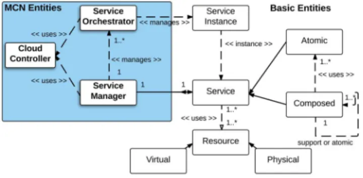
C. Basic Architectural Entities
There are some basic entities in the MCN architecture, which should be noted to further understand the architecture. A
Service is defined by OASIS [11] as “a mechanism to enable
access to one or more capabilities, where the access is provided using a prescribed interface and is exercised consistent with constraints and policies as specified by the service descrip-tion.” A service can be identified by its interface and type. A Service Instance (SI) is defined as a single instance of a service from a specific service type, while a Service Instance Component (SIC) is an integral, internal element of a SI. A Resource corresponds to any physical or virtual compo-nent of limited availability within a computer or information system, therefore a Physical Resource is any element of hard-ware, software or data that is part of a larger system, while
Fig. 2. MCN Architecture – Logical Entities.
a Virtual Resource is a temporal partitioned fraction of any physical resource.
Given that MCN delivers cloud-native services, which can be subdivided in two broad categories: Atomic Service that corresponds to an indivisible service that executes a par-ticular singular business or technical function. Thus, it is not subject to further decomposition. Composed Service that aggregates/combines services together with orchestration logic. Both Atomic and Composed Services can be used to create further composed services. MCN supports two types of composed services: Support Services that provide targeted, specific functionality for use by any other support or MCN service. These can be thought of being the platform services of MCN which other services use to carry out specific func-tions. MCN Services are services with their own domain specific orchestration logic and may use support and/or atomic services.
D. MCN Service Management Framework
When setting out on creating the MCN service manage-ment framework it was important that the existing standardised functional architectures and interfaces (e.g., those used in mobile telecom systems; EPC, IMS) be maintained and that only the software architecture (internal design) be modified. This ensures the interoperability of the delivered SI, even where a multi-stakeholder environment (aka a service sys-tem or service network [12]) is required. A big challenge for MCN was to present a consistent, common and standards based control/management interface. To achieve this all com-ponents are compliant to the Open Cloud Computing Interface (OCCI) standard [13]. The following key MCN architectural entities, illustrated in Fig.2, are now described in brief.
1) Service Manager (SM): provides an external interface that presents one or more service types that can be instanti-ated by a tenant. It is responsible for managing a collection of service orchestrators. The SM’s programmatic interface (north-bound interface, NBI) is designed to provide either a CLI and/or a UI. Through the NBI, the SM gives the a tenant or another upstream SO capabilities to create, list, detail, update and delete tenant service instance(s). Its “Service Catalogue” contains a list of the available service types offered by the provider. Its “Service Repository” is the component that pro-vides the functionality to access the “Service Catalogue”. The “SO Management” (SOM) component has the task of receiving requests from the NBI and overseeing, initially, the
deployment and provisioning of the service instance. Once the instantiation of a service is complete, the SOM component can oversee tasks related to the execution of the SO and its later disposal. SOs are tracked in the “SO Registry” component.
2) Service Orchestrator (SO): The SO oversees the end-to-end orchestration and composition of a SI. Once created and running, it manages the SI and its SICs and is isolated per-tenant. Generally, only one SO is instantiated per each SI, however for reliability and quorum more can be provided. The instantiated SO is always associated with the SM that created it. It is a domain specific component as it has all the specific orchestration logic encoded within it. In particular, it is responsible for SIC instantiation and configuration, triggering of scaling and migration of SICs according to metrics collected within or by the runtime component of the CC. When the SO is created by the SM, it is just a bundle of code resources, known as the SO bundle. What is contained in the SO bundle is domain specific, however these items are expressed as either the SO implementation (SO-I), the SO’s Service Template Graph (STG) or the Infrastructure Template Graph (ITG). The SO-I is the actual code implementation for the creation of a SI and implements methods mapped to the MCN lifecycle. The STG contains all the required supporting and atomic ser-vice needed by the SO. The ITG defines how resources should be composed to be able to host Service Instance Components (SIC). For example, the MCN Analytics service requires two virtual machines: one to handle compute execution and one to handle the storage backend. The SO has also interfaces with the SICs, to enable high availability features, to detect and recover faulty service instances, and with the monitoring ser-vice, to enable scaling mechanisms, by observing certain Key Performance Indicators (KPIs). In MCN, the SO is divided into two components, the SO Executor (SOE) and SO Decision (SOD) components. The Executor is responsible for imple-menting the main service life cycle, except for the runtime phase. Its only responsible for initiating the runtime phase. The runtime phase is provided by the SOD. The SOD is responsi-ble for receiving notifications and/or metrics from SICs (e.g., virtual machines).
3) Cloud Controller (CC): abstracts from specific technolo-gies that are used in the technical reference implementation. Indeed, the service bundle is created through the CC. This component plays a key role in the support of several infras-tructures (e.g., CloudSigma, OpenStack) and platform tech-nologies (e.g., Google App Engine, Azure, OpenShift). The CC’s OCCI-based API’s specification has been submitted to the OCCI group [14] and will figure in the upcoming 1.2 standard.
Fig. 3 details the MCN orchestration architecture and depicts the relation between the MCN components with Platform-as-a-Service (PaaS) and Infrastructure-as-a-Service.
E. MCN Service Platform and Interoperability
The MCN Service Platform is a collection of services that can be leveraged by developers. This set of services all exhibit the principles and architectural elements defined in the previous sections, as illustrated in Fig. 4.
Fig. 3. MCN Architecture – Orchestration Perspective.
Fig. 4. Available Services in the MCN Service Platform. TABLE I
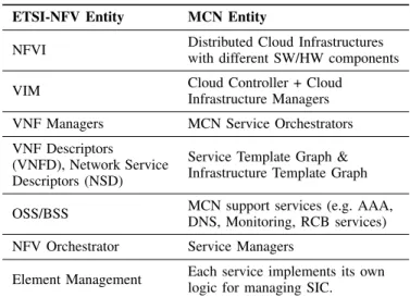
ETSI-NFVANDMCN MAPPING
There are many services all delivered as-a-Service supported in the platform, including EPCaaS and RANaaS with support-ing and operational services such as Monitorsupport-ing as a Service (MaaS) and Rating, Charging & Billing Service (RCBaaS), known as Cyclops.4 A challenge in all platforms is to ensure common and interoperable interfaces.
F. MCN and ETSI NFV
As shown in Table I, all the functionalities provided by the NFV entities part of the initial NFV architecture are
supported by the MCN architecture and its components. In particular, the NFV Infrastructure is provided by a distributed cloud infrastructure composed by heterogeneous software and hardware components. This NFVI is exposed to the MANO layers via the Cloud Controller and Cloud Infrastructure Manager, providing the VIM interface towards its consumers. As per the NFV approach, each different service (VNF in the ETSI NFV terminology) is managed by a specialized Service Orchestrator (VNFM) handling the Service Template Graph (VNFD) requesting the allocation of compute, storage, and networking resources via the Service Manager (NFVO) or directly to the Cloud Controller using an Infrastructure Template Graph. The management of each SIC is specific per Service, while the OSS/BSS functionalities are provided by the support services. Finally, the Service Managers are exposing APIs towards the EEU for allowing the on-demand deploy-ment of composed services (Network Services in the ETSI NFV terminology).
The entities of the MCN architecture implement the orches-tration function of the corresponding NFV entities. MCN SO is responsible to instantiate, scale, update, migrate and terminate SICs (i.e., NFVs). The MCN SO resides on each adminis-trative domain it manages, like the NFVM. Each Element Management (EM) with close orchestration of MCN SO assure FCAPS management. MCN SM assures the reference points functions, namely the NFVO - NFVM and NFVO-NFVI.
MCN began its architecture development before ETSI NFV, however other than terminology (see Table I), the two approaches to providing services or virtual network func-tions on-demand are largely the same. A common distinction between MCN and NFV relies in the fact that NFV considers multi-tenancy in multi-tenant hosting scenarios or only in the scope of Infrastructure as a Service (IaaS). MCN considers the tenant-based on-demand provisioning of services in dis-tributed cloud infrastructures. Typically, a NFV system is used for the internal purposes of an organisation (i.e., mapped to a Infrastructure) and does not expose these publicly as Amazon EC2 or Microsoft Azure would with their cloud resource systems.
G. MCN and Open Source
The MCN architecture was developed and deployed in the MCN testbeds as detailed in Section III and has now been released as the Hurtle project.5
III. EVALUATIONSCENARIOS ANDTESTBEDS This section describes scenarios, the testbeds and the cloud-native core network architecture.
A. Proof of Concept Scenarios
Two Proof of Concept (PoC) scenarios have been considered for assessing the effectiveness of the MCN architecture in sup-porting a fully cloudified mobile network: the IP Multimedia System (IMS) and the Digital Signage Service (DSS).
5http://hurtle.it
Fig. 5. DSS PoC Architecture.
1) DSS PoC: evaluates Over-the-Top (OTT) applications playing content through digital signage services. This scenario is based on a fictitious MVNO, that requires the deployment of a Digital Signage Service (DSS), that needs to integrate and orchestrate all service components required for a DSS sys-tem. Such systems allow the deployment of Digital Signage Network (DSN) composed by digital signs (such as LCD, LED, plasma displays) connected via wireless connections to content and digital player servers. Fig. 5 shows the compo-sition of the different services required for the DSS PoC. Besides the DSSaaS service, the deployment of the DSS system requires other “X-as-a-Service” components from the cloud infrastructure and network provider, such as AAAaaS for authentication and authorization, performance monitoring of services and instances (MaaS) and SLA assurance (SLAaaS). Information Centric Networking (ICNaaS) is also required to enhanced content distribution (e.g., based on the location of mobile users, or according to their preferences). The RCBaaS allows the charging for consumed resources (e.g., storage and compute resources). Once appropriately placed and instanti-ated, these service components are managed during runtime by appropriate and suitable algorithms (including horizontal scaling operations). DSSaaS also employs Load Balancing (LBaaS) to enable scaling and load sharing between Content Management Servers (CMS) that provide the content to DSS Players, according to the user profile and preferences that are managed by the Main Content Repository (MCR) interfacing with Databases (DBaaS) to store content and user data.
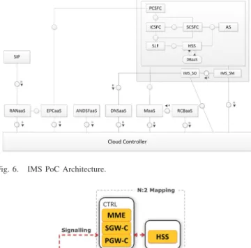
2) IMS PoC: enables IMS services for mobile users con-nected to 3GPP networks. This scenario is based on a fictitious MVNO requiring the deployment of a composed service con-taining all the service components required for offering video and voice over LTE as illustrated in Fig.6. Besides IMSaaS, the deployment of the IMS system requires other services from the cloud infrastructure and network provider, such as RANaaS and EPCaaS providing connectivity to the UE. In par-ticular, for enabling an efficient virtualization of the Evolved Packet Core (EPC), its architecture is re-designed in a cloud-native fashion, named N:2 deployment model. With the N:2 concept, the current N functions represented by each of the standard 3GPP EPC components are merged into two new
Fig. 6. IMS PoC Architecture.
Fig. 7. EPC N:2 deployment model.
ones aiming at better scalability and delay, while not losing the interoperability.
The EPC N:2 architecture, depicted in Fig.7, aims at reduc-ing the EPC service delay through mergreduc-ing of control entities such as Mobility Management (MME), Serving Gateway -Control (SGW-C) and Packet Data Network Gateway - -Control (PGW-C) on the same software in the same virtual machine, while the data plane handling is executed in a single Switch virtual machine. For efficiency reasons, the Home Subscriber Server (HSS) was also hosted separately. With this approach, the interfaces S11 and S5 are internal to the control vir-tual machine, allowing a lower delay for session control procedures. In addition, the architecture enables independent scaling mechanism for the switch at user plane. The proposed N:2 architecture deployment differs from 3GPP and related approaches [15], in the way of the functions are highly uniform and enable separate data and control plane scalability.
Apart from the IMS, EPC and the RAN, the proof of con-cept includes an additional set of services which provide added value to the architecture, including the Monitoring (MaaS), internal operator Domain Name Server (DNSaaS) as well as Access Network Discovery and Selection (ANDSFaaS) for providing subscribers with mobility related policies and Rating Charging and Billing (RCBaaS) for metering and providing billing information of the resources consumed by the service. B. Testbeds
The evaluation work uses five testbeds, as illustrated in Fig.8. Testbeds are interconnected through the deployment of
Fig. 8. MCN Testbeds Regions.
different regions, which rely on different IaaS solutions. All regions support at least the OpenStack Heat service, which is used to provide the basic resources that enable each ser-vice instance. All regions use the identity provider (OpenStack Keystone) of RegionOne (Bart). This allows users to consume services in all regions with a single set of credentials, as well as ensuring that MCN composed services can be supported across multiple data centres, some using different technol-ogy to OpenStack such as Joyent Trident or CloudSigma’s proprietary, albeit based on open source, technology stack.
The Service Managers (SM) are located on the ZurichCloudSigma region, which is based on CloudSigma IaaS. The Cloud Controller is located on RegionOne of Bart testbed. Service Orchestrators, deployed in the PaaS, are executed on OpenShift at RegionOne (Bart). Services are spread throughout all testbeds according to the service requirements.
The RegionOne (Bart) is located in Winterthur, being oper-ated by ICCLab, and includes OpenStack Kilo, which has the role of Identity Provider, based on keystone. The installation of OpenStack runs on CentOS and is based on the packstack tool.6 This region also hosts the OpenShift v3.
The region EURE (EURECOM) is located at Sophia Antipolis, and is managed by Eurecom. It includes OpenStack Juno in a single-host all-in-one setup, which is connected to a NI/ETTUS USRB B210 radio frontend (2x2 MIMO). This region uses Linux Containers (LXCs) to provide appro-priate performance to RANaaS with OpenAirInterface sup-port. The host runs a Linux low-latency kernel with the SCHED_DEADLINE real-time scheduler.
The UBern region is operated by the CDS group of the University of Bern. The OpenStack version is Kilo running on Ubuntu 14.04.3 LTS and has been deployed using the Mirantis Fuel tool.7 Ubern consists of a cloud controller, a computing node, and a Storage Area Network.
The ZurichCloudSigma (CloudSigma) region employs a proprietary KVM-based cloud stack with a custom API. This region has available an Icehouse RDO deployment8 on a Ubuntu 14.04 system. Heat is configured with the CloudSigma Heat plugin [16], together with PyCloudSigma, a library for interacting with the CloudSigma API.9
6https://github.com/stackforge/packstack
7https://www.mirantis.com/products/mirantis-openstack-software 8https://www.rdoproject.org/
TABLE II
OPENSHIFTPLATFORMS FOREVALUATION(SETTINGS PERVM)
The WinterThurSDC (Burns) is located in Winterthur and is operated by the ICCLab. It offers a Joyent’s Triton IaaS platform (i.e., Smart Data Center, SDC)10 and an OpenStack Heat service for Juno and kilo (WinterThurSDCKilo) versions. The Infrastructure common to most of the testbeds is OpenStack, with different versions and specific configurations (e.g., in software defined networking components). The several IaaS are optimized for supporting configuration and updates of the Service Instance Components at runtime.
OpenShift v3 has been employed as the PaaS to enable effective means to run the workload of service orchestra-tors. The support for CloudFoundry has also been consid-ered during the project but has complexity issues associated when compared to OpenShift, namely on small scale deploy-ments. OpenShift v3 is based on docker images managed by Kubernetes runtime and offer great performance improvements in comparison to OpenShift v2, as presented in Section V-A, and in D6.2 [17].
IV. EVALUATIONMETHODOLOGY
This section describes the evaluation methodology employed in MCN to assess PaaS and service performance in the integrated DSS and IMS scenarios. The evaluation relies on a logging framework, based on graylog [18] for collecting performance indicators of service lifecycle (see Section II). Key Performance Indicators (KPIs) of the several services have been collected in MaaS, at domain and service/resource levels. PoCs include functional and non-functional evalu-ations of the MCN orchestration functions summarized in Section II-F, with exception of the migration function that is not evaluated.
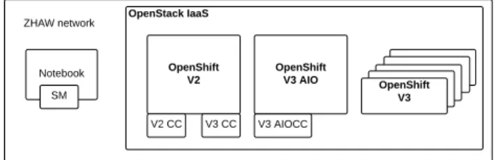
A. Evaluation of PaaS
The evaluation of PaaS aims to identify the PaaS per-formance with different versions and deployment options of OpenShift: v2, v3 and v3 all in One (AIO), as per Table II. The evaluation scenario, depicted in Fig. 9 includes different OpenShift Platforms deployed in the Bart testbed, with the notebook acting as an EEU. For accuracy, the cloud controller component has been configured for each PaaS, with the excep-tion of OpenShift v3 that employs the cloud controller hosted at OpenShift v2. The notebook is connected directly to the datacentre where all PaaS are running.
The evaluation methodology includes calls for service instantiation to the service manager that is configured to use
10http://www.joyent.com
Fig. 9. OpenShift PaaS Evaluation Scenario.
the specific cloud controller of the different PaaS. The test-ing includes ten runs. The key performance indicators include the time of the MCN service lifecycle phases, namely Init - creation of required resources to execute the SO; Activate - initialization of SO; Deploy - deployment of resources associated with service; and Provision - configuration of SICs [19].
B. Functional DSS and IMS PoC Evaluation
The evaluation includes indicators of the correct behavior of each service in the composed scenario and KPIs of the services in the DSS & IMS PoCs, as detailed in Table V.
The Bart testbed includes the deployment of AAAaaS, DSSaaS and SLAaaS. The CloudSigma testbed includes RCBaaS, the remaining services of DSS PoC are deployed in the UBern testbed.
The overall functional evaluation of the DSS PoC scenario includes the steps. An End User (EU) is involved with the per-spective of addressing the business perper-spective, which requires agreements in SLAaaS to provide/configure the necessary cre-dentials to authenticate DSS players in AAAaaS, as well as the media contents configuration in DSSaaS and ICNaaS. The sequence ends with an end user displaying the contents in the players, and generating the invoice in RCBaaS.
In the IMS PoC, EU also performs several steps, which include the configuration of the network selection policies in the ANDSFaaS, for instance, LTE interface has the high-est priority in equipments also Wi-Fi capable. A successful attachment procedure enabling the UE to connect to an access network is also included.
C. DSS PoC Evaluation
The purpose of the evaluation is to assess the suitability of the proposed architecture for an Over-the-Top DSS service that is composed of several individual services, namely DSSaaS, MaaS, DNSaaS, ICNaaS, AAAaaS, SLAaaS, RCBaaS.
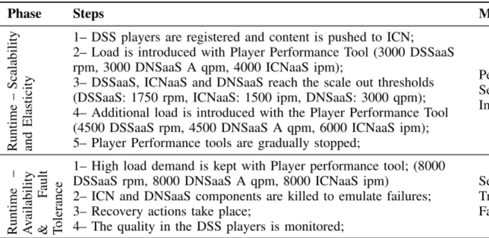
The Non-Functional evaluation of DSS PoC includes per-formance of service lifecycle phases, namely Deployment, Provisioning, Runtime & Operations, and Disposal. The met-rics evaluated in each phase are summarized in Table III. In the elasticity and fault-tolerance evaluation a specific perfor-mance tool is used to emulate the behavior of a high number of players requesting playlist updates to the DSS-CMS com-ponent, and also performs DNS A queries to DNSaaS and retrieves content from ICNaaS. Emulated player performance tool [20] disables all the caching mechanisms in player side, namely DNS cache and local media content cache. In addition, the tool specifies the load in DSSaaS in terms of requests per
TABLE III
DSS POC NON-FUNCTIONALKPIS
minute (rpm), in queries per minute (qpm) for DNSaaS and in interests per minute (ipm) for ICNaaS.
The measurement methodology includes the SM and SO built-in capabilities to identify the start and end of scaling out/in events, the aggregation of measurements in the logging service and the aggregation of performance data in the moni-toring service. In the availability and fault tolerance evaluation, the integrated service behaviour is also observed, mainly in terms of recovering from failures.
D. IMS PoC Evaluation
The purpose of this evaluation is three-fold: (i) to assess the suitability of the MCN architecture proposed towards a fully cloudified mobile network in a IMS scenario; Second, to determine the performance of key telecommunication ser-vices, namely RAN and EPC in a cloudified mobile network; Finally, to assess the performance of the N:2 deployment model of the virtualized EPC. The IMS PoC scenario is com-posed by several services, namely IMSaaS, EPCaaS, RANaaS, DNSaaS, MaaS, RCBaaS and ANDSFaaS. Differently from the DSS scenario, this IMS scenario chains three different main services: RANaaS, EPCaaS and IMSaaS for providing an end-to-end Mobile Network Infrastructure offering stan-dard telco services. Services are deployed in different testbeds geographically located in distinct cities, having the core net-work deployed in UBern (EPCaaS, IMSaaS), while RANaaS is deployed in EURE testbed. ANDSaaS, enabling network selection policies is deployed in Bart, the remaining services are deployed as in the DSS PoC.
Measurements between Eurecom and UBern testbeds report on an observed one-way delay that is in the order of 25-35 ms. In addition, the eNB is configured for a 5 MHz channel bandwidth in band 7 (2.5/2.6 GHz) operating with single antenna (SISO). A single UE is used for both the func-tional and non-funcfunc-tional evaluations. The UE is located at the distance of 5 meters from the eNB, and remains static.
1) EPCaaS Data Plane Performance: The assessment of the scaling support of EPC, includes the scale-out of switch nodes and the load transfer between the Switch entities, as depicted in Fig. 10. In this assessment, the switches hosts
Fig. 10. ECPaaS N:2 Scaling scenario. TABLE IV
EPCAAS NON-FUNCTIONALKPIS
are deployed as virtual machines with 4 vCPUs and 2 GB of RAM, using the benckmarking tool with metrics and steps detailed in Table IV, and with a duration of 40 s for each experiment.
2) RANaaS and EPCaaS Control Plane Performance: We use the LTE attachment to verify whether the RANaaS is successfully providing the required eNB functionality as well as to evaluate the proper integration with the EPCaaS. An attachment procedure is triggered by the UE resulting in a successful attachment to the OAI-based eNB of RANaaS and to the EPCaaS. In the functional tests measurements accounted the average delay of the overall attachment procedure.
V. EVALUATIONRESULTS
This section presents the results of the PaaS evaluation, of DSS and IMS PoC evaluations.
A. Evaluation of PaaS
The main difference between OpenShift v2 and OpenShift v3 in our context is where the build of the application takes
Fig. 11. OpenShift PaaS Performance data. TABLE V
DSS & IMS POC FUNCTIONALRESULTS
place. For OpenShift v3 this is done once by the user in advance, prior to deployment. For OpenShift v2 on the other side, the build is performed every single time during the deployment on the PaaS (the Activate phase).
The results of the evaluation depicted in Fig.11, show the advantages of OpenShift v3 over OpenShift v2. On average, the Init, Deploy and Provision phases take the same amount of time. The real difference is on the Activate phase where OpenShift v2 has to perform the build on every deployment.
The orchestration performance becomes ever more impor-tant as services are of composed architecture. First, every (composed) service has to be managed by a running orches-trator. Second, services often come in chains, in which one service requires input from others previously instantiated. Therefore, the performance gain between OpenShift v3 over OpenShift v2 is of a great importance.
Fig. 12. Deployment and Provisioning sequence in DSS PoC (run 5).
Fig. 13. Deployment and Provisioning duration in DSS PoC. B. Functional Results of DSS and IMS PoCs
Results of the functional evaluation of the services in the DSS and IMS PoCs are depicted in Table V. Based on the evaluation and results, it is concluded that services are well-integrated and functionalities leveraged from each other.
Based on the evaluation results, one may conclude that services are well-integrated and functionalities leverage from each other. In fact, there is a strong dependency between RANaaS and EPCaaS as well as with DNSaaS in order to have a fully operational IMS PoC scenario. These services are chained for both the data and control plane.
C. DSS PoC Results
DSS PoC non-functional results are discussed here. 1) Non-Functional–Service Lifecycle: The results of the service lifecycle rely on the execution of five runs in dis-tinct time periods from the deployment towards the disposal phase. The deployment and provisioning sequence of services in the DSS PoC are depicted in Fig.12for a specific run. The duration of the deployment and provisioning sequence in the DSS PoC are depicted in Fig.13and is based on the average duration in seconds.
The ability to automatically deploy and provision an on-demand composed OTT service in about 5 minutes, integrated in the MVNO infrastructure and connected to its support services (e.g., ICNaaS and CDNaaS) to improve the qual-ity of service experience and optimize latency, contrasts with the time required for deployment of a network of exter-nal digital signage where manual actuation that can take
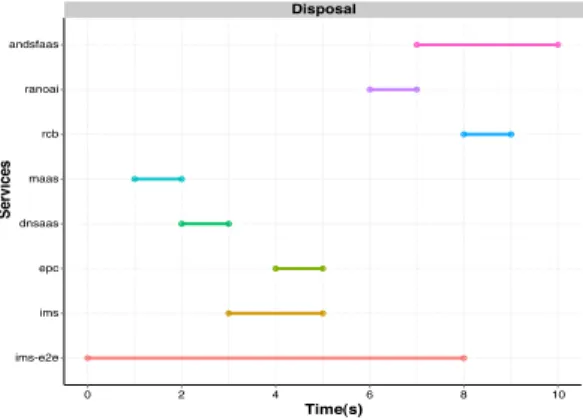
Fig. 14. Disposal sequence in DSS PoC (run 5).
Fig. 15. Disposal duration in DSS PoC.
hours or days given the number of services involved in this scenario, and their inherent complexity (number of ser-vices and virtual machines configured). The parallelization of operations contributes to this time, as depicted in Fig. 12, namely in the deployment phase, since resources are cre-ated simultaneously in the several testbeds. In the provision phase, the dependencies of services can be observed, for instance the endpoint of MaaS is configured in different ser-vices, ICNaaS, DSSaaS, AAAaaS and DNSaaS. Besides the employed testbeds, it should also be noticed that each service has its own specificities (e.g., different number of virtual machines and network configurations).
As in the deployment phase the parallelization of the disposal operation leads to deletion of resources in about 8 seconds, as depicted in Fig. 14, for a specific run, which is acceptable, given the fact that these resources are deleted from different testbeds. The main difference between services regarding disposal relies on the number of service instance components that need to be removed from the IaaS. In partic-ular, it can be observed that the dss-e2e service requires more time to dispose since it requires the successful disposal from other services, as depicted in Fig. 15.
Based on the results achieved in the deployment and dis-posal phases, we can argue that the proposed architecture provides enough flexibility to enable Over-the-Top services, such as DSS including a considerable number of composed services, with an acceptable performance from a business perspective (e.g., a full deployment is possible in minutes).
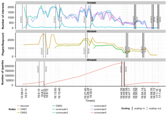
2) Non-Functional–Scaling and Elasticity: The scaling and elasticity results are depicted in Fig. 16, where it can be
Fig. 16. Scalability and Elasticity in DSS PoC.
observed the instants on which each individual service (DSS, DNS and ICN) has scaled out.
Based on the results obtained, we can analyse in detail the integrated scenario behaviour as being consistent with the services that scale. For instance, the number of scaling-in operations is followed by the same number of scalscaling-ing-out operations, when load decreases. Despite the specificities of each service, the scaling operations occur in a synchronized way, for instance when DSSaaS triggers the first scale-out at instant 16:08, DNSaaS also scales-out. This also applies to the second scale-out moment of DSSaaS that occurs coordinated with ICNaaS at instant 16:27.
This puts in evidence that the thresholds configured in DSSaaS, ICNaaS, and DNSaaS for scaling enables coordinated scaling operations in the cloudified mobile network. Such logic instrumented in the service orchestrator of each service, must be defined in the business phase (see SectionII), which lever-ages the potential of the proposed architecture in meeting the SLAs agreed initially.
DSSaaS includes the CPU KPI for triggering the scale-out operation. CPU is the only KPI being used because the results of the performance analysis of the component showed that the it was primarily CPU intensive. The scale-out operation occurs when the CPU utilization exceeds 60% for all CMS service instance components (around 2000 rps). The scale-in operation is triggered when CPU decreases to values under 10% usage for all CMS components. ICNaaS triggers the scale-out based on the CPU and Number of interests KPIs. The scale-out of a CCNx occurs when the number of interests exceeds a threshold of 6000 and/or CPU exceeds 75% of usage. The scaling-in operation is verified when such KPIs have a non usage in terms of CPU or when the number of interests decreases to a value bellow 1200. On the other hand, DNSaaS employs the number of Queries Per Second (QPS), to trigger the scale-out within two thresholds: 150 QPS to scale-out a second backend server; 300 QPS for a third backend server. The scaling-in operation for only two backend servers occurs when the QPS are in the range [150,300], and for only one server when bellow 150.
Load sharing between CMS components of DSSaaS relies on the LBaaS provided by OpenStack. In the employed testbed, bart, the Heat service does not fully support the update operation for LBaaS. Therefore, the performance loss verified
Fig. 17. Recovery Performance.
in DSS after each scaling out event is due to the recreation of the LB component and the detachment and reattachment of the CMS components on the update. After each scale out, load requests are properly shared between available CMS compo-nents. In this evaluation two scale out operations are triggered after the load introduced by the performance tool, followed by two scale in operations when the load is removed, thus reducing resource usage when no longer required.
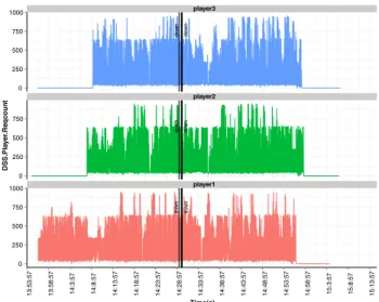
3) Non-Functional–Availability and Fault Tolerance: Fig.17depicts the availability and fault tolerance evaluation, it can be seen the recovery performance of ICNaaS and DNSaaS. There is no down time in a failure scenario, due to the com-ponents redundancy implemented in ICNaaS and DNSaaS for the core functionalities of the respective services.
The provided fault-tolerance mechanisms to increase avail-ability, proved to be efficient given the failures of internal components on the different services. Although the digital signage network is completely dependent on DNSaaS and ICNaaS, components failure does not cause an impact of the quality of service perceived from the players, as depicted on Fig.18. The fault-tolerance mechanisms, also denominated as High-Availability (HA) are specific to each service. DNSaaS employs a reachability metric to verify that a certain com-ponent (i.e., backend server) is not available. Therefore, the SO performs a reachability test for the instantiated backend server and if a successful reply is not received in a certain configurable threshold (20 s), the component is considered as unavailable and a recovery procedure is triggered. One may argue that the threshold of 20 s may introduce a considerable delay in the recovery process, nevertheless, this value is con-sidered to avoid detecting a server as unavailable due to the congestion in the network or other failure events related to net-work performance. ICNaaS uses the monitoring functionalities of MaaS. The SO of ICNaaS polls frequently MaaS to gather the status of CCNx routers, if a down/unreachable status is reported for a component, the recovery process is triggered to the component with failure(s).
The DSSaaS results show that players requests rate and players download rates are not affected after the failure events which means that the contents can be retrieved and requests can be resolved anytime during the tests. Player download
Fig. 18. Quality perceived by DSS players in terms of number of requests.
rates are slightly affected during a short time due to the load increase in the remaining ICN routers. This can be observed for all players around 14:30.
The ICNaaS results show that the service fault-tolerance mechanisms perform as expected even with the failure of three components, as illustrated in the three failure events, approx-imately at 14:29. In total, 3 edge routers (out of 5) were shutdown to simulate a datacentre failure. As there is a load balancing mechanism with link state detection in place, load was automatically distributed among the working routers, with no visible impact for DSS players during the recovery phase. However, load increased substantially and scaling out opera-tions were needed to ensure that performance would not be affected. Therefore, the same scaling mechanisms, thresholds and safeguards of previous tests were used and the service recovered completely to the defined bounds (within scale-out and scale-in thresholds) in about 20 minutes.
The DNSaaS results show that the service fault-tolerance mechanisms perform as expected with the failure of one com-ponent, as illustrated in the failure event, approximately at 14:29. The failure was introduced in the dns-server3, which after recovery (instance 14:34) starts to receive additional load. There is no down time during the recovery procedure, as dns-server1 is able to perform the query resolution. It can be observed that the recovery starts at 14:29:57 when the failure occurred at 14:29, these 32 seconds of difference are due to the recovery mechanism. The first step in the recovery process of DNSaaS includes disposing affected (e.g., failing) resources. If the load does not decrease, the service returns to the same state before failure after some minutes, at instant 14:34, due to the scale-in and scale-out.
D. IMS PoC Results
IMS PoC non-functional results are presented here. 1) Non-Functional–Service Lifecycle: The deployment and provisioning sequence of services in the IMS PoC are depicted in Fig. 19. The duration of the deployment and provisioning sequence in the IMS PoC are depicted in Fig.20.
Fig. 19. Deployment and Provisioning sequence in IMS PoC (run 5).
Fig. 20. Deployment and Provisioning duration in IMS PoC.
Fig. 21. Disposal duration in IMS PoC (run 5).
Inline with the results of the DSS PoC, we can argue that the proposed architecture is able to support an all-IP Next Generation Network in cloud infrastructures. In particular, and with a telco provider perspective, the overall deployment time is reduced to 4 minutes (255 seconds), having the core services distributed in testbeds located in distinct geographical loca-tions. These results include RANaaS with OAI support [21], EPCaaS based on Fraunhofer FOKUS Open5GCore [22] and IMSaaS based on OpenIMSCore [23]. Once again, the par-allelization in the deployment phase contributes greatly to such achievement. The support of the Pay-as-You-Go model is demonstrated with the disposal performance lying in times around 30 s, as depicted in Fig. 21 and22. Given the com-plexity associated with the composed services of the IMS PoC,
Fig. 22. Disposal duration in IMS PoC.
Fig. 23. Switch Scale Out and Load Balancing scenario.
such timings indicate that the proposed architecture enables an efficient resource reuse, which is relevant for cloud providers. 2) EPCaaS Data Plane Performance: The results for N:2 architecture data plane evaluation are illustrated in Fig.23. As input for the first 30 seconds the data traffic is linearly increas-ing from 10 Mbps to 200 Mbps and is split between the two switches. After that, the data traffic is linearly decreasing from 200 Mbps to 10 Mbps. One of the switches is removed from the system after 30 seconds. All the data traffic is forwarded to the remaining switch. As expected, the delay of the data packets remains in the limit of 10 ms for both of the data flows. When stopping the switch, the packet loss increases, however remaining into the normal limits of less than 1%. The evaluation results show that it is feasible to load balance the data traffic, even within the same data flow between multi-ple switches as well as to scale-in and scale-out the data path without any state related constraints. Further optimizations aim to reduce the average delay of 10 ms.
3) RANaaS and EPCaaS Control Plane Performance: Currently, the RANaaS does support scaling/flexibility as it is pre-dimensioned to constantly support its maximum capac-ity throughout the whole experiment. However, it adjusts the required runtime as a function of channel bandwidth, maximum modulation and coding scheme (MCS), number of antennas, and the execution platform. Other important non-functional measures are performance-based related to the control plane delay (e.g., measured through the UE attach-ment delay), and data-plane (e.g., throughput, delay, jitter, packet loss ratio). Here, we concentrate on the description of the signaling delay in the UE attachment procedure and uplink/downlink channel capacity. Other parameters such as
Fig. 24. Data Plane Evaluation.
data plane’s jitter and delay are heavily affected by the geo-graphical distance between EURE and UBern, which is around 600 km, and data transmission between eNB and EPC over publicly available Internet links (RTT of around 50 ms), which make them non-representative. The packet loss is close to 0 for the unsaturated air-interface. Initial attach procedure latency on the control plane was obtained by setting a tracing point at eNB as well as a large number of measurement points in the RAN and EPC. More particularly, Wireshark packet ana-lyzer is used to measure the control-plane latency between UE-eNB, eNB-EPC and in the EPC. In our setup, the total control-plane latency observed for the completion of initial attach procedure is 1113 ms. From the results we note that the main bottleneck impacting the control signaling latency resides on the radio access network. Indeed, the procedures involving only the core network take less than 40 ms, without considering the exchange of the messages over the network. This is because of the internal RAN signaling at the Radio Resource Control (RRC) layer, as well as the delay induced by the virtualization.
4) Combined RANaaS and EPCaaS Data Plane Performance: Fig. 24 depicts RTT results by varying the packet size (64, 768, 2048, 4096, 8192 in byte) and inter-departure time (1, 0.8, 0.4 , and 0.2 in second) reveal an average total data-plane latency of 50 to 120 millisecond. As expected, higher RTT values are observed as packet size and inter-departure time increase. However, RTT variations are observed as the inter-departure time and packet size, which is due to backhaul connection between eNB and EPC as well as virtual switching happening both at eNB and EPC.
VI. RELATEDWORK
This section analyzes related work, focusing on five of the large scale projects with most relevance for MCN: T-NOVA, iJOIN, MODAClouds, Coco Cloud and CloudScale. We also describe the most relevant software-based RAN implementations that may be leveraged to provide a fully cloudified RAN.
T-NOVA is probably the project with more similarities with MCN. It aims at designing and integrating an end-to-end archi-tecture for NFV services, targeting all the layers including applications and infrastructure components [24]. The eval-uation methodology includes several validation areas, such as functional and performance of NFVs, reliability of net-work services, portability and stability, and monitoring of
virtual network services. The evaluation methodology also encompasses system and service-level metrics, such as time to deploy, scale-out/scale-in delay, data plane performance such as maximum achievable throughput. Different testbeds are employed to evaluate the benefits of T-NOVA, but the Radio Access Network (RAN) service is not included in the evalua-tion methodology. Besides, T-NOVA is at an earlier stage, and the integrated evaluation work is still ongoing.
Following a different approach, iJOIN aims at enabling the concept of RAN-as-a-Service (RANaaS), for optimizing the access and backhaul in heterogeneous networks [25]. The main contributions of the iJOIN architecture are RANaaS (RAN-as-a-Service) and Joint Radio Access/Backhaul design and optimisation. The conducted evaluation is performed in three main testbeds: (i) RANaaS, (ii) joint access & back-haul (iii) and SDN [26]. Evaluation metrics are specified per testbed and include the decoding time for the performance of RANaaS, system throughput, block error rate and number of occupied CPUs. Data rate, latency and energy consump-tion metrics are considered for the backhaul testbed, while handover latency, signaling load are considered in the mobil-ity management of the SDN testbed relying on IPv6 and OpenFlow mechanisms. Despite the extensive evaluation cri-teria, the evaluation results are based on simulations and lack integration towards a fully cloudified network solution.
MODAClouds took the End User perspective in first place, developing a subset of tools to facilitate the portability of ser-vices and applications to the cloud, with a decision support system based on key performance indicators. One of such tools includes the SpaceOps 4Clouds [27] – able to model the resource cost of a service in multiple cloud environments. Evaluation included four testbeds with diverging requirements and the developed tools for different PaaS (Google App Engine, Azure) and IaaS (OpenStack, CloudSigma) [28].
Coco Cloud [30], [33] aims at improving the security over traditional cloud deployments, focusing on the automation of management mechanisms for data sharing agreements. This project included three pilots with distinct requirements, namely a Public Administration information exchange, Healthcare images and medical data access, and the corporate business data exchange using mobile devices. The performed evalu-ation considers a Goal, Question, Metric (GQM) approach, on which objectives are mapped into metrics for the specific pilots, with the drawback of being tied to pilots. It supports quantitative and qualitative metrics, such as successful rate of viewing medical reports or communication channel protection. CloudScale [31], [32] aims at enabling analysis and predic-tion and at solving scalability issues on software-based ser-vices, deployed on clouds. The evaluation focuses mainly an e-commerce application, according to multiple areas (capac-ity, elasticity and efficiency) in OpenStack and Amazon Web Services. In addition multiple stakeholders are included, such as service providers and system developers. The CloudScale evaluation methodology has the advantage of supporting new systems, not yet deployed and already running.
TableVIsummarizes the evaluation scope of each of these projects. Functional aspects include assessment on the func-tionalities of service(s), while non-functional aspects include
TABLE VI
RELATEDWORK ANDEVALUATIONSCOPE
evaluation of scalability, elasticity, cost, and performance regarding deployment, provisioning and disposal of service(s) in cloud infrastructures.
Considering the cloud RAN, the feasibility of LTE RAN software implementations over General Purpose Processors (GPPs), which are radically different from traditional approaches provided through Application-Specific Integrated Circuits (ASICs), Digital Signal Processors (DSPs), or Field-Programmable Gate Arrays), was successfully demon-strated in the recent works [34]. The existing software based implementations of the LTE evolved Node B (eNB) include: a) Amarisoft LTE solution, which is a pure-software fully-functional LTE eNB [35], b) Intel solu-tions featuring energy efficiency and high computing per-formance using a hybrid GPP-accelerator architecture and load-balance algorithms among a flexible IT platform [36] and c) OpenAirInterface (OAI) developed by EURECOM imple-menting eNB (a Software Defined Radio (SRD)) and EPC as open source [37].
A. MCN vs ETSI-NFV Implementations
Considering that MCN claims to be compliant with the ETSI NFV MANO specification it is also important to briefly list existing open source projects. At the time of writing this paper, several new projects provide an implementation of the ETSI NFV MANO specification. First of all, ETSI launched OpenSourceMANO (OSM) [38] initiative providing a refer-ence architectural framework that implements MANO func-tionalities. OSM Rel.0 integrated Rift.io [39], OpenMANO, and Juju [40] in a single platform. Open Baton [41], a frame-work implemented by Fraunhofer FOKUS and TU Berlin, launched in October 2015, provides a comprehensive reference implementation of ETSI NFV MANO. Open Baton is built from scratch upon the NFV information model, and provides a very modular architecture based on a messaging system. Open Baton has been further extended for supporting OCCI
as northbound interface and can be integrated within MCN as an additional service orchestrator. Open-O [42] represents a new initiative under the Linux Foundation providing an open source solution for service orchestration. Nonetheless, Open-O did not have any available releases. Juju is a very mature VNF Manager supported by Canonical. It provides manage-ment and orchestration of services which has to be defined and stored as charms in the Juju repository. Very recently AT&T announced the launch of their open source initiative Enhanced Control, Orchestration, Management & Policy (ECOMP) [43]. ECOMP aims to provide a comprehensive framework for the management of SDN and NFV functionalities.
Concluding, the MCN project encompasses a fully cloudi-fied mobile network infrastructure proposal that considers OAI in RANaaS and Open5GCore [22] for EPCaaS differentiating with all the solutions presented in terms of features provided. Furthermore, the underlying MCN architecture also distin-guishes from the related work in the area of ETSI NFV MANO by assessing the mobile network infrastructure in diverse IaaS using a hierarchical orchestration approach, via the OCCI interfaces exposed by each different domain.
VII. CONCLUSION
This paper provided complex PoC results in the direc-tion of the adopdirec-tion of cloud computing benefits by Mobile Network Operators (MNO) for key telecommunication ser-vices in the access and core networks, besides the current cloud services already exploited for non-critical services such as application and data storage. Towards this goal, we propose an architecture that includes a business lifecyle optimising CAPEX/OPEX and a technical lifecycle leveraging a deploy-ment model virtualizing MNO’s core network (i.e., EPC) and RAN elements.
The proposed architecture introduces logical entities that are compliant with the ETSI-NFV model, to enable an effi-cient service management, from the design till the deployment
phase, within different service delivery models (IaaS, PaaS and SaaS). The service orchestrator entity enables the defini-tion of the composidefini-tion between services, and the specificadefini-tion of computing resources (IaaS). The cloud controller abstracts the specificities of the platforms (PaaS). The service man-ager, in conjunction with the remaining entities, enables the concept of X-as-a-Service (SaaS). The proposed architecture also envisions foundations for the deployment of virtual-ized access and core networks, addressing the placement of specific network functions of EPC in several compo-nents (e.g., virtual machines) and compocompo-nents of RAN. The adherence to lifecycle allows a clear separation between the creation (deployment) and configuration (provisioning) of ser-vice instance components, promoting the parallelization of operations, which at the end reduces the time for service delivery.
The Mobile Cloud Network architecture has been evalu-ated in integrevalu-ated DSS and IMS PoCs scenarios in terms of functional and non-functional key performance indicators. The scalability and elasticity results in the IMS PoC validate the N:2 deployment model for the access and core network by enabling the load balancing between data path compo-nents of the EPC with delay of data packets in the range of 10 milliseconds with low packet loss ratios. The integration of RANaaS and EPCaaS, deployed in distinct and geograph-ically separated testbeds, lead to a data plane performance of 50 to 120 milliseconds, depending on the packet size and inter-departure time. From the perspective of the individual services, the following innovative items were developed and proven as feasible with the MCN testbed. For RAN, we have proven that the upper-bound of less than 3 ms for the eNB pro-cessing which has a serious impact on the user performance can be achieved in visualized environment based on LXC and KVM with almost the same performance as bear metal. The prototype was validated with control of OpenStack and Heat with both container and KVM virtualisation. For EPC, the architecture was engineered for a more performant one for the cloud deployments, as well as to consider the private network requirements specific to flexible parallel cloud deployment. For the IMS along with the basic virtualization, the testbed showcased seamless scalability of control plane components.
All the three services are integrated with a large number of platform support services including DNS and monitoring through this offloading functionality from the services them-selves. Through this we have proven that cloud infrastructures are able to provide the support services needed for cloud-native telecom services, and are able to scale with other services according to the configure scale-in and scale-out thresholds. In fact, such scaling when properly configured, does not impact the quality of end user applications, as shown in the DSS PoC scenario with the DSS Players in terms of download rates. From the perspective of deployment and provisioning of the service to be instantiated, the key optimisation that the MCN service lifecycle afforded was the parallelisation of the services required to deliver a full end-to-end service composition. Also given the split of deployment and provisioning phases this allowed for the reduction in managing service dependency res-olution as at the end of the deployment phase all services and
their details were well known to the end-to-end orchestrator, responsible for the composition.
The current telco operators are taking the direction of network function virtualization as the main paradigm for the evolution of the network components and cloud services. The proposed architecture provides a set of innovative features especially in regard to the composition of the end-to-end ser-vices, as well as in the area of bringing cloud-native features to the different network functions implementations.
REFERENCES
[1] J.-M. Bohli, N. Gruschka, M. Jensen, L. Lo Iacono, and N. Marnau, “Security and privacy-enhancing multicloud architectures,” IEEE Trans.
Depend. Secure Comput., vol. 10, no. 4, pp. 212–224, Jul./Aug. 2013.
[2] H. Hawilo, A. Shami, M. Mirahmadi, and R. Asal, “NFV: State of the art, challenges, and implementation in next generation mobile networks (vEPC),” IEEE Netw., vol. 28, no. 6, pp. 18–26, Nov./Dec. 2014. [3] R. Riggio, M. K. Marina, J. Schulz-Zander, S. Kuklinski, and
T. Rasheed, “Programming abstractions for software-defined wire-less networks,” IEEE Trans. Netw. Service Manag., vol. 12, no. 2, pp. 146–162, Jun. 2015.
[4] D. Tuncer, M. Charalambides, S. Clayman, and G. Pavlou, “Adaptive resource management and control in software defined networks,” IEEE
Trans. Netw. Service Manag., vol. 12, no. 1, pp. 18–33, Mar. 2015.
[5] P. Mell and T. Grance, “The NIST definition of cloud computing,” NIST
Spec. Publ., vol. 800, p. 145, Oct. 2011.
[6] J. Hwang, K. K. Ramakrishnan, and T. Wood, “NetVM: High per-formance and flexible networking using virtualization on commodity platforms,” IEEE Trans. Netw. Service Manag., vol. 12, no. 1, pp. 34–47, Mar. 2015.
[7] ETSI NFV Industry Specification Group, “Network functions virtualisa-tion (NFV); use cases,” Oct. 2013, version V1.1.1, Ref. DGS/NFV099, pp. 28–32, 2013. [Online]. Available:http://goo.gl/fShBc4
[8] F. Dudouet, P. Harsh, S. Ruiz, A. Gomes, and T. M. Bohnert, “A case for CDN-as-a-service in the cloud: A mobile cloud networking argument,” in Proc. IEEE ICACCI, New Delhi, India, Sep. 2014, pp. 651–657. [9] S. Sesia, I. Toufik, and M. Baker, LTE—The UMTS Long Term
Evolution: From Theory to Practice, 2nd ed. Chichester, U.K.: Wiley,
2009.
[10] T. Erl, SOA: Principles of Service Design, vol. 1. Upper Saddle River, NJ, USA: Prentice Hall, 2008.
[11] OASIS. (2012). Reference Architecture Foundation for
Service-Oriented Architecture. [Online]. Available: http://docs.oasis-open.org/ soa-rm/soa-ra/v1.0/soa-ra-cd-02.pdf
[12] U. Riss, M. Villinger, M. Sprenger, S. Haase, and V. Milanova, “MCN D2.3 market analysis and impact of mobile cloud concepts,” Nov. 2013. [Online]. Available:http://goo.gl/5majTh
[13] A. Edmonds, T. Metsch, A. Papaspyrou, and A. Richardson, “Toward an open cloud standard,” IEEE Internet Comput., vol. 16, no. 4, pp. 15–25, Jul./Aug. 2012.
[14] OCCI. (2016). Open Cloud Computing Interface. [Online]. Available: http://occi-wg.org
[15] J. Kempf, B. Johansson, S. Pettersson, H. Lüning, and T. Nilsson, “Moving the mobile evolved packet core to the cloud,” in Proc. IEEE
WiMob, Barcelona, Spain, Oct. 2012, pp. 784–791.
[16] MobileCloudNetworking. (2016). MCN CloudSigma Heat Plugin. [Online]. Available: https://github.com/MobileCloudNetworking/cs-heat-plugin
[17] D. Palma and P. Simões (Oct. 2014). D6.2: Initial Report on Testbeds, Experimentation, and Evaluation. [Online]. Available:
http://goo.gl/LHbRKF
[18] I. Graylog. (2016). Graylog—Open Source Log Management That
Actually Works. [Online]. Available:https://www.graylog.org [19] T. Metsch et al., “D3.2: Infrastructure management foundations
compo-nents first release,” Apr. 2014. [Online]. Available:http://goo.gl/wFqEfG [20] S. Ruiz and M. Vallipor. (2016). DSS Performance Tool. [Online].
Available:https://github.com/MobileCloudNetworking/dssaas/ [21] OpenAirInterface. (2016). 5G Software Alliance for
Democratising Wireless Innovation. [Online]. Available: http://www.openairinterface.org
[22] F. Fokus. (2016). Open5GCore—The Next Mobile Core Network Testbed