04 August 2020
Repository ISTITUZIONALE
Designing for Additive Manufacturing - Product and Process Driven Design for Metals and Polymers / Pakkanen, JUKKA ANTERO. - (2018 Oct 04).
Original
Designing for Additive Manufacturing - Product and Process Driven Design for Metals and Polymers
Publisher:
Published
DOI:10.6092/polito/porto/2714732
Terms of use:
Altro tipo di accesso
Publisher copyright
(Article begins on next page)
This article is made available under terms and conditions as specified in the corresponding bibliographic description in the repository
Availability:
This version is available at: 11583/2714732 since: 2018-10-04T17:56:31Z Politecnico di Torino
Doctoral Dissertation
Doctoral Program in Materials Science and Technology (XXX Cycle)
Designing for Additive Manufacturing
-
Product and Process Driven Design for
Metals and Polymers
By
Jukka Antero
Pakkanen
Supervisor(s):
Prof. Paolo Fino Prof. Matteo Pavese Prof. Paolo Minetola Dr. Diego Manfredi
Doctoral Examination Committee:
Prof. Matthew Gilbert, Referee, University of Sheffield, UK
Prof. Andrea Gatto, Referee, University of Modena and Emilia Romana, Italy Politecnico di Torino
Declaration
I hereby declare that, the contents and organization of this dissertation constitute my own original work and does not compromise in any way the rights of third parties, including those relating to the security of personal data.
Jukka Pakkanen 19.09.2018
* This dissertation is presented in partial fulfillment of the requirements for
I would like to dedicate this thesis to the search for new and continuous technological advancements of humankind that will make lives better and safer
Acknowledgment
I would like to acknowledge all the people who have worked in collaboration with me for compiling the PhD thesis and the career leading to this point. Special thank you for the different universities that have hosted me and Politecnico di Torino for this ride. I would like to thank my team in Politecnico di Torino and the team leaders professor Paolo Fino, Dr. Diego Manfredi for guiding me in additive manufacturing. Also thanks to professors Luca Iuliano, Paolo Minetola and Matteo Pavese. Team members in AMMLab at Istituto Italiano di Tecnologia: Dr. Elisa Ambrosio, Dr. Flaviana Calignano, Dr. Massimo Lorusso, Dr. Riccardo Canali, Dr. Abdollah Saboori, Dr. Alberta Aversa, Francesco Trevisan, Giulio Marchese, Giulio Cattano, Simone Parizia and Aresh Mazdai. Additional thank you for the numerical simulation group in University of California San Diego with professor Alicia Hyunsun Kim. She and her group for providing a direction to topology optimization.
The last acknowledge is for my family and wife Dr. Anna Wołczyk, who shared the PhD ride with me until the end and helped me in the difficult times when the road is not so clear to make it until finish...
There are times when rough shapes take different forms in our imagination as this AlSi10Mg cylinder shows us. Thank you for everyone who was left unmentioned. You are the unknown heroes.
Abstract
Additive Manufacturing (AM) has broken through to common awareness and to wider industrial utilization in the past decade. The advance of this young technology is still rapid. In spoken language additive manufacturing is referred as 3D printing for plastic material and additive manufacturing is left as an umbrella term for other materials i.e. metallic materials and ceramics. As the utilization of AM becomes more widespread, the design for additive manufacturing becomes more crucial as well as its standardization.
Additive manufacturing provides new set of rules with different design freedom in comparison with subtractive manufacturing methods. This is thought to empower product driven designs. However, in the AM methods there are process driven variables that limit the designs functions to what could be manufactured. There are often extra steps after production to finalize the design. Topology optimization utilizes product driven design where material is only where it is needed to be. The design is computed without taking into account any manufacturing constrains and only the design in the final application stage is achieved. Topology optimization algorithm is explored in detail for two algorithms. Then these algorithms are compared in case study I to gain better understanding of the algorithms functions. Case study I consists of 2D and 3D algorithms where a 3D level set method algorithm was written for this purpose.
The concept of designing for additive manufacturing is examined for polymeric materials in case study II with a help of topology optimization design software tailored for additive manufacturing market. The parts are manufactured with different AM methods, examined and results are explained. The results show an interesting effect of anisotropy and the manufacture methods effect in the part mechanical properties.
On the other hand, process driven design and its concepts important as the manufacturing method dictates, what can and should be done economically. Metal AM process constraints are explored in case study III through accuracy studies in metal additive manufacturing at laser powder bed fusion (LPBF) technology. Accuracy and surface studies are concluded to gain a better understanding of the process and manufacturability of metal parts. The gain knowledge is explaned and examples are shown how these are utilized to make metal parts with tailored properties and with minimal post processing needs.
Contents
Declaration ... I Acknowledgment ... III Abstract ... IV Contents ... V List of Publications ... VII List of Figures ... VIII List of Tables ... XIV List of Equations ... XV Abbreviations ... XVI1. Introduction ... 1
2. Literature Review ... 3
2.1. History of Additive Manufacturing ... 4
2.2. Standardization of Additive Manufacturing ... 5
2.2.1. Terminology ... 7
2.2.2. AM Methods ... 10
2.2.3. List of Published AM Standards ... 13
2.2.4. Outlook ... 14
2.3. Manufacturing Methods Used Experimentally ... 15
2.3.1. Material Extrusion ... 15
2.3.2. Selective Laser Sintering ... 20
2.3.3. Laser Powder Bed Fusion (LPBF) ... 22
2.3.4. Post Processing in AM ... 29
2.4. Product Driven Design ... 30
2.4.1. Topology Optimization ... 30
2.4.2. Solid Isotropic Material with Penalization (SIMP) ... 31
2.4.4. Other Topology Optimization Algorithms ... 40
2.4.5. Commercial Software ... 40
2.4.6. Using Topology Optimization ... 41
2.5. Process Driven Design ... 43
2.5.1. Polymeric Materials ... 43
2.5.2. Metallic Materials ... 49
3. Case Studies ... 53
3.1. Case Study I: Product driven design ... 53
3.1.1. 2D Comparison: SIMP and LSM Algorithms ... 53
3.1.2. 3D Comparison: SIMP and LSM Algorithms ... 55
3.1.3. Summary ... 59
3.2. Case Study II: Application of Product Design ... 60
3.2.1. Topology optimization and design ... 60
3.2.2. Manufacture and Testing ... 64
3.2.3. Selective Laser Sintered Material ... 66
3.2.4. Material Extrusion Material ... 74
3.2.5. Summary ... 80
3.3. Case Study III: Metal Application of Process Design ... 81
3.3.1. Manufacture Equipment ... 81
3.3.2. Design of holes ... 83
3.3.3. Design of tubes ... 91
3.3.4. Design of Hydraulic Components ... 99
3.3.5. Summary ... 105
4. Conclusions ... 107
5. Recommendations for Future Work ... 110
References ... 112
Appendix I – Finite Element Analysis ... 123
List of Publications
2015
C. Semini, J. Goldsmith, D. Manfredi, F. Calignano, E.P. Ambrosio, J. Pakkanen, D.G. Caldwell. “Additive manufacturing for agile legged robots with hydraulic actuation”, Advanced Robotics (ICAR), (2015)
2016
J. Pakkanen, R. Vallant, M. Kičin. ”Experimental investigation and numerical simulation of resistance spot welding for residual stress evaluation of DP1000 steel”, Welding in the World, Vol. 60, Iss. 3, pp 393-402, (2016)
J. Pakkanen, F. Calignano, F. Trevisan, M. Lorusso, E.P. Ambrosio, D. Manfredi, P. Fino. “Study of Internal Channel Surface Roughness Manufactured by Selective Laser Melting in Aluminum and Titanium Alloys”, Metallurgical and Materials Transactions A, Vol 47, Iss. 8, pp. 3837–3844 , (2016)
2017
F. Calignano, M. Lorusso, J. Pakkanen, F. Trevisan, E. P. Ambrosio, D. Manfredi, P. Fino. “Investigation of accuracy and dimensional limits of part produced in aluminum alloy by selective laser melting”, The International Journal of Advanced Manufacturing Technology, Vol 88, Num 1 – 4, pp. 451–458, (2017)
F. Trevisan, F. Calignano, M. Lorusso, J. Pakkanen, A. Aversa, E.P. Ambrosio, M. Lombardi, P. Fino, D. Manfredi. “On the Selective Laser Melting (SLM) of the AlSi10Mg Alloy: Process, Microstructure, and Mechanical Properties”, Materials, 10, 76, (2017)
J. Pakkanen, D. Manfredi, P. Minetola, L. Iuliano. ”About the Use of Recycled or Biodegradable Filaments for Sustainability of 3D Printing. State of the Art and Research Opportunities”, Smart Innovation, Systems and Technologies, Vol. 68, pp. 776 – 785, (2017)
List of Figures
Figure 1. Structure of AM Standards [8]... 6
Figure 2. Binder jetting ... 10
Figure 3. Direct energy depositing process in wire or powder base method. . 11
Figure 4. Material jetting process ... 11
Figure 5. Sheet lamination process. ... 12
Figure 6. Vat photopolymerization process. ... 12
Figure 7. Roadmap for Standardization. SASAM [8] ... 15
Figure 8. Schematic of material extrusion. ... 16
Figure 9. Porosity between extrusion layers [20] ... 17
Figure 10. Tensile strength and elongation of fabricated parts with material extrusion. ... 18
Figure 11. Laser sintering process. [38] ... 21
Figure 12. Laser Powder Bed Fusion [39] ... 22
Figure 13. Gas atomized powder [42] ... 24
Figure 14. Water atomized powder [42] ... 24
Figure 15. Spheroidized powder [42] ... 25
Figure 16. Direction of the scan. ... 25
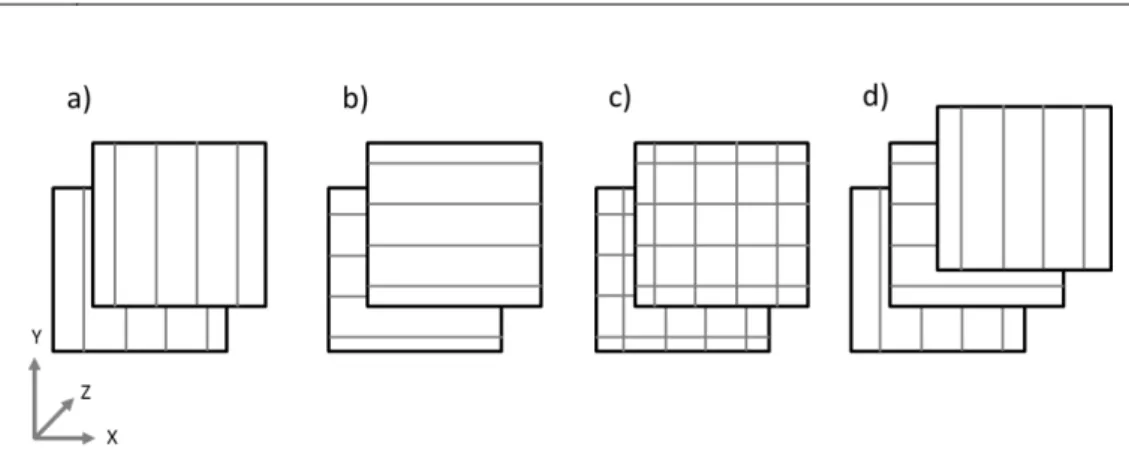
Figure 17. Scanning strategies: a) and b) linear and parallel, c) perpendicular and d) alternative scanning ... 26
Figure 18. Stripe pattern ... 26
Figure 19. Checkerboard pattern ... 27
Figure 20. Island pattern in scanning strategy... 27
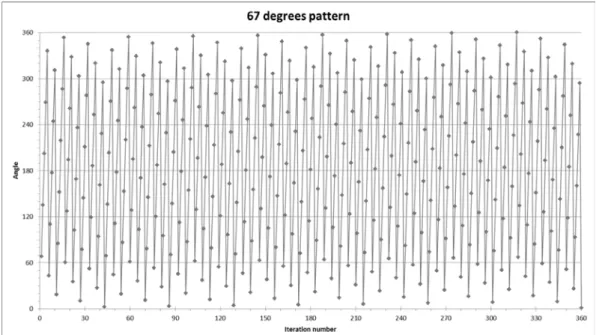
Figure 21. Scanning strategy shift of 67-degrees in EOS M AM-machines depending on the layer. ... 28
Figure 22. Different angles what laser has with on 67-degree angle rotation before the pattern repeats. ... 28
Figure 23. Topology optimization algorithm. ... 31
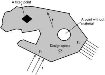
Figure 24. Generalized shape design problem in two-dimensional space for finding optimal material distribution. ... 32
Figure 25. Compliance problem in SIMP interpolation. ... 35 Figure 26. Checkerboard problem visualized, a) the design space, b) checkerboard [44] ... 37
Figure 27. Effect of mesh refinement into design [44] ... 37 Figure 28. Representation of a level set curve. ... 38 Figure 29. Topology optimized and milled Brembo GP4 RX brake caliper. [59] ... 42
Figure 30. Brake disk of a bicycle. Left Shimano commercial disk and right simulated result from Altair OptiStruct [60]. ... 42
Figure 31. 3D model simplified into layered structure. ... 46 Figure 32. Layers effect by staircases on surface roughness [71] ... 52 Figure 33. Cantilever, a constrained beam from one side and a weight on the other side. ... 54
Figure 34. 150x50 mesh cantilever optimized: left Matlab SIMP [78] algorithm, right Matlab LSM [79] algorithm. ... 55
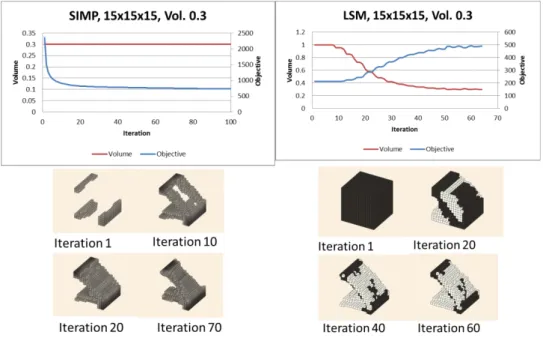
Figure 35. Cantilever in 3D model. ... 56 Figure 36. 15x15x15 mesh cantilever optimized with Matlab: left 3D SIMP and right 3D LSM. ... 56
Figure 37. CAD model printed out from small 3D cantilever simulation: left 3D SIMP and right 3D LSM. ... 57
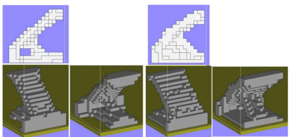
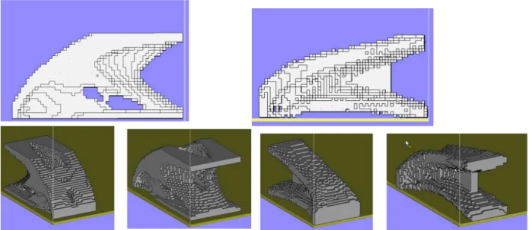
Figure 38. SIMP 3D convergence of 60x30x30 mesh ... 57 Figure 39. CAD model printed out from large 3D cantilever simulation: left 3D SIMP and right 3D LSM. ... 58
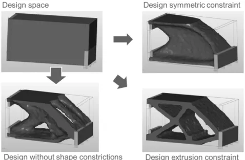
Figure 40. 3D printed model of 3D LSM output... 58 Figure 41. Altair Hyperworks Inspire simulation with the large cantilever 60x30x30 problem. Different design constrictions: free, symmetry, extrusion. ... 59
Figure 42. Flexural three-point bend specimen design: a) schematic of the design, b) design in Inspire 2016. Red: design space, silver: non-design space to equally distribute the load, round cylinders: support and force cylinder. ... 62
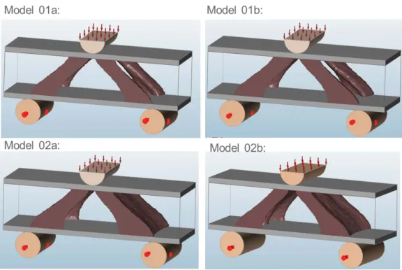
Figure 43. Topology optimized result EOS PEEK. ... 62 Figure 44. Topology optimization result with ABS Plus P430 at strength of 52 MPa (Model 01) and 32 MPa (Model 02). The a parameter set has pressure load of 5MPa with 1.2 factor of safety and b parameter set has pressure load of 4 MPa with 1.5 factor of safety. ... 63
Figure 46. EOS P800 laser sintering machine... 64 Figure 47. Manufacturing directions for EOS peek (left) and ABS (right) .... 65 Figure 48. Three-point bending test machine... 66 Figure 49. Left: Safety factor. Right: tension (orange) and compression (green) areas in the model EOS PEEK. ... 66
Figure 50. Pressure test results for PEEK sample X-, Y- and Z-direction. Design force 1000 N, break point 1200 N. ... 67
Figure 51. Pressure test results for PEEK sample X-direction. Design force 1000 N, break point 1200 N ... 68
Figure 52. Pressure test results for PEEK sample Y-direction. Design force 1000 N, break point 1200 N ... 68
Figure 53. Pressure test results for PEEK sample Z-direction. Design force 1000 N, break point 1200 N ... 68
Figure 54. Broken specimen build in showing break pattern. ... 69 Figure 55. Material sample from pressure test specimen ... 69 Figure 56. One phase breaking pattern when the whole structure fails at same time: a) specimen without load, b) specimen at max load, c) specimen failure. ... 69
Figure 57. Two-phase breaking pattern. Bend test of EOS PEEK sample manufactured in Z-direction (E_Z_1): a) Specimen without pressure, b) specimen under load, c) specimen cracked under load on top left corner, d) crack propagation under load and new crack under the pressing tool, e,f) failure of the specimen ... 70
Figure 58. Material slice according to build direction. ... 71 Figure 59. Material in direction 1, top X-direction, middle Y-direction, bottom Z-direction. ... 72
Figure 60. Material in direction 2, top X-direction, middle Y-direction, bottom Z-direction. ... 72
Figure 61. Fracture surface along Z-direction PEEK specimen... 73 Figure 62. Vickers micro hardness (HV0.1) of the PEEK slices with 100g weight. ... 74
Figure 63. Average hardness measurement with Berkovich nano hardness tip. ... 74 Figure 64. Hardness profile of X-direction alongside of Z-axis with hardness measurement with Berkovich nano hardness tip. ... 74
Figure 65. Safety factor between high stressed model 01 and low stressed
model 02. ... 75
Figure 66. Tension and compression maps between high stressed model 01 and low stressed model 02. ... 76
Figure 67. Model 01b, 3 point pressure test with x-, y- and z-directions. Design force 1000 N, breakpoint 1200 N. ... 76
Figure 68. ABS Y-direction breaking: a) before pressing, b) ultimate pressing force, c) yield of the strut pointed by the arrow and the cutting of the strut, d) failure of the strut made the piece fail also on the lower side corner. ... 77
Figure 69. ABS X-direction breaking: a) before pressing, b) strut on the left side and behind gives away, c) second left struts gives away. ... 78
Figure 70. ABS Z-direction breaking: a) before pressing, b) breakpoint, a crack has formed below of the presser firstly and then to the left bottom of a strut. ... 78
Figure 71. ABS Plus P430 X-direction bend test. ... 79
Figure 72. ABS Plus P430, Y-direction bend test. ... 79
Figure 73. ABS Plus P430, Z-direction bend test. ... 79
Figure 74. Cross section of failed ABS parts: a) x-direction, b) z-direction... 80
Figure 75. AM-machine: EOS EOSINT M270. ... 82
Figure 76. British hexagonal 50 pence coin with a constant radius. ... 84
Figure 77. STL-approximation of a round object. ... 86
Figure 78. Circles mentioned in [96] standard. a) Minimum zone reference circle, b) least squares reference circle, c) minimum circumscribed reference circle and d) maximum inscribed reference circle. Figure from [98] ... 87
Figure 79. Accuracy hole sample a) vertical and b) horizontal ... 87
Figure 80. Comparison of LOM and stereo microscope in making a mask of the hole. 1a) LOM 5x image of 1mm diameter hoe and 1b) its hole mask. 2a) stereomicroscope 8x image of the same hole and 2b) its mask. ... 88
Figure 81. Hole roundness values in comparison to the hole diameter values. Black: horizontal hole and grey: vertical hole. ... 89
Figure 82. 1 mm diameter hole from horizontal build (left) and vertical build (right) ... 90
Figure 83. 4 mm diameter hole from horizontal build (left) and vertical build (right) ... 90
Figure 84. A hollow cylinder fabricated with different building angles to test the change in internal surface roughness. ... 91
Figure 85. Manufactured hydraulic component shapes from AlSi10Mg and Ti6Al4V. ... 91
Figure 86. Manufactured hydraulic component shapes from AlSi10Mg and Ti6Al4V at 0-angle. ... 91
Figure 87. Tubes manufactured from AlSi10Mg in different angles. ... 92 Figure 88. Unsupported bend in dimension reduction part of a piece leading to sagging effect on the piece. ... 93
Figure 89. FESEM image of the internal surfaces of the cylindrical shapes produced by SLM with different angles: a) 0 angle top, b) 0 angle bottom, c) 45 angle top, d) 45 angle bottom, e) 60 angle top and d) 60 angle bottom surface. ... 95
Figure 90. Dark stylus tracks representing the surface roughness tester indentation on internal surfaces: a) 0° angle bottom and b) 45° angle bottom surface with not optimal stylus path. ... 96
Figure 91. Roughness measurements on AlSi10Mg and Ti6Al4V internal surfaces ... 97
Figure 92. Difference in cross-section roughness between a) bright field and b) dark field images. Dark field shows the surface structure below the cross section. ... 98
Figure 93. Comparison of measured Rmax and cross-section peak to bottom measurements. ... 98
Figure 94. The two S-shaped aluminum manifolds made by Direct Metal Laser Sintering (DMLS): just after shot-peening (on the left), and after testing with pressurized oil (on the right). ... 100
Figure 95. Internal channel of the manifold (left: as build, right: tested with oil) and the stereomicroscopically examined spots: 1. Fixing cavity, 2. Inside channel and 3. Curve. ... 101
Figure 96. Inside cavity reachable with shot peening and machined with threads. ... 101
Figure 97. Inside channel of the manifolds: after shot peening (on the left) and tested with oil (on the right). ... 102
Figure 98. Corner of the manifolds: after shot peening (on the left) and tested with oil (on the right). ... 102
Figure 99. CAD model of HyQ2Max with close-up views of the highly-integrated hydraulic manifolds of the two hind legs. [100] ... 103
Figure 100. CAD models of hydraulic manifolds for the legs of the HyQ2Max robot. Left: traditionally manufactured manifold (green parts). Right: highly integrated AM manifold. [100] ... 103
Figure 101. Orientation of hydraulic block a) 45-degree slope, b) 5-degree tilt for recoating blade angle, c) hydraulic block with support structures in Magics 18 and d) the final part. ... 104
Figure 102. The hydraulic manifold a) after shot peened and b) during pressure testing. ... 105
Figure 103. Stiffness matrix element ... 123 Figure 104. Two stiffness elements... 124
List of Tables
Table 1. Common material extrusion materials ... 17
Table 2. LS Materials available... 22
Table 3. Process variables during LPBF manufacturing. ... 23
Table 4. Design rules for polymeric 3D printing materials [63] ... 47
Table 5. Material properties used in simulation ... 63
Table 6. Material composition EOS AlSi10Mg Wt. % [92] ... 82
Table 7. Material composition EOS Ti64 Wt. % [93] ... 82
Table 8. EOSINT M270 fabrication parameters. ... 83
Table 9. Shape describing quantities and descriptions listed by Rodriguez et al. in [97] ... 85
List of Equations
Equation 1. Internal virtual work of an elastic body at equilibrium u for virtual
displacement v. ... 32
Equation 2. Minimum compliance for global stiffness problem ... 33
Equation 3. FE approximation of the optimization problem. ... 33
Equation 4. Optimization problem in global form ... 33
Equation 5. Stiffness tensor with distributed material. ... 34
Equation 6. SIMP function ... 34
Equation 7. Penalization factor equations. ... 34
Equation 8. Lagrangian equation from the SIMP compliance problem. ... 35
Equation 9. Stiffness and density design update equations. ... 36
Equation 10. strain energy for intermediate densities at iteration K. ... 36
Equation 11. Level set function equation. ... 38
Equation 12. The mean curvature of the LSF interface. ... 39
Equation 13. Signed distance function. ... 39
Equation 14. General LSM optimization problem statement. ... 39
Equation 15. Level set method optimization problem. ... 40
Equation 16. Elemental stiffness matrix force equilibrium equations. ... 123
Equation 17. Elemental stiffness matrix force equilibrium equations in matrix form. ... 123
Equation 18. Global stiffness matrix force equilibrium equations. ... 124
Equation 19. Elemental stiffness matrix force equilibrium equations in matrix form. ... 124
Equation 20. Elemental stiffness matrix force equilibrium equations showing the conjunction of the matrixes. ... 124
Abbreviations
AM Additive Manufacturing
ASTM American Society for Testing and Materials ISO International Organization for Standardization
SASAM Support Action for Standardization in Additive Manufacturing SLA Stereolithography Apparatus
SLS Selective Laser Sintering DMLS Direct Metal Laser Sintering SLM Selective Laser Melting LPBF Laser Powder Bed Fusion CMB Controlled Metal Build-up DMD Direct Metal Depositing
CNC Computer Numerically Controlled FFF Fused Filament Fabrication
EBM Electron Beam Melting
EBPBF Electron Beam Powder Bed Fusion
LEAP-engine Leading Edge Aviation Propulsion Engine
RP Rapid Prototyping
OEM Original Equipment Manufacturer
FEM Finite Element Method FEA Finite Element Analysis
DOF Degree of Freedom
LSM Level Set Method
LSF Level Set Function
FESEM Field-Emission Scanning Electron Microscope SEM Scanning Electron Microscope
AFNOR French committee for Standardization
UNM 920 French technical body for AM standardization VDI German committee for Standardization
GPL Committee on Production and logistics from Germany AENOR Spanish committee for Standardization
AEN/CTN
116 Spanish technical body for AM standardization SIS Swedish committee for Standardization
SIS/TK 563 Swedish technical body for AM standardization BSI British committee for Standardization
AMT/8 British technical body for AM standardization CEN European Committee for Standardization
CENELEC European Committee for Electrotechnical Standardization ESO Evolutionary Structural Optimization
BESO Bi-directional Evolutionary Structural Optimization ECP Electrochemical Polishing
MZCI Minimum Zone Reference Circle LSCI Least Squares Reference Circle
MCCI Minimum Circumscribed Reference Circle MICI Maximum Inscribed Reference Circle LOM Light Optical Microscope
ABS Acrylonitrile Butadiene Styrene PEEK Polyether Ether Ketone
SIMP Solid Isotropy Material with Penalization
IM Injection Moulding
Chapter 1
1.
Introduction
A computer aided design (CAD) is manufactured by a machine into an object. It is called Additive Manufacturing (AM). Why is it called additive manufacturing and not 3D printing? Additive manufacturing is old name for the process that has been used in the industrial applications since the dawn of the technology. A layer on another layer is added “additively” and then it is repeated countless of times. This was also referred as rapid prototyping (RP) as it was the first successful application of AM. To simplify the process for consumers and users the process has been called many names as solid photography in the 1970’s and lately 3D printing. It is easier to imagine developing a film in 3D or printing a 3D object than additive manufacturing. Therefore 3D printing has stuck to the public. It is defined in ASTM standard to be polymeric layer manufacturing when additive manufacturing is defined for other materials printing, like metals and ceramics, and for industrial applications.
This is a PhD thesis consists of topics in additive manufacturing (AM) and design topics related to designing for the additive manufacturing. Additive manufacturing is manufacture method where instead of substracting material, the material is added to create the shape. The scope of the thesis is to give overview about the latest developments in AM and insights into product and process driven design. This is done by dividing the thesis into five section.
Firstly the relevant literature to understand the process and design methods is provided in Chapter 2: Literature Review. AM methods are described from technical and historical point of view. Additionally an insight to the future trends of the technology and standardization is presented. Design point of view is provided through deep dive into topology optimization (topopt) and its possibilities for AM. Additionally AM process constraints are provided in
polymeric and metallic materials, what are utilized in designing for AM. Therefore, giving the product and process driven design overviews for AM.
Followed by is Chapter 3: Case Studies, where the main findings throughout the PhD career is gathered. In Product driven design the case study includes comparison of two different topology optimization codes through 2D and 3D topology optimization codes. Simple topopt codes are important as these provide overview of the optimization process into more complex cases. Powerful commercial software is then used to optimize and simulate parts for correct material properties before manufacturing with polymer AM processes. Case studies second half consists from metal AM and provides solutions for challenges in metal manufacturing with laser powder bed fusion (LPBF) equipment. Study of AM manufacture from simple holes providing accuracy for the process is extended to tubes and the knowledge is used in practical application of AM hydraulic manifold.
The Chapter 4: Conclusions will summarize the overall findings and the last Chapter 5: Recommendations for Future Work will provide future outlook for research directions.
Chapter 2
2.
Literature Review
Design is an important part of manufacture. Design has been thought through functionality as well as the aesthetic aspects of the final product. In mechanical pieces the functionality is the most important when in a high-end item like jewelry the beauty outweighs other functions. Therefore, it is necessary to look the design from multiple angles.
It is possible to consider what can be designed without considering manufacturing constraints. This is product driven design and it is often seen in high end luxury products where the amount of resources is not spared when achieving the goal. On the other hand, economic constraints often forces the designers to choose the best manufacturing method for a product by the scale of
what can be manufactured. When manufacturing constraints are taken into account the design becomes a process driven and designed to the specific manufacturing process. For example, an I-beam can be manufactured with different manufacturing methods (i.e. forging, extrusion, welding, machining) and the same shape is gain. However, the road to the shape is not the same and the resources spend are not equal.
Additive manufacturing has been called a revolution in design because it offers a new way of thinking the fabrication of a part. Instead of subtracting material, it is possible to add material. When building a difficult shape is time consuming to machine from a large volume, AM offers the possibility of just building the shapes and nothing more leading to material saving as there is less metal scrap from subtracting the material. The customer is not paying premium for the extra removed material that ends in recycling, but just for the used material. Another economical aspect in additive manufacturing is that adding
material takes time as well as subtracting material. Hence, adding less material or making more difficult shapes that reduce the final build volume saves build time and material needed leading to cheaper costs. This is usually referred with marketing slogan “in additive manufacturing complexity is for free.”
2.1.
History of Additive Manufacturing
The inventions of additive manufacturing have been a long process. First key components for AM, photo resins, were invented in 1950’s by DuPont. Laser technology came along with first experiments of curing photo resin in 1960’s by Battelle Memorial Institute. In 1970’s Dynell Electronics Corporation called their technology as solid photography. A name that helped the public to visualize the process in a similar way as 3D printing is used currently. [1]
Stereo lithography can be claimed to have emerged in 1980 when Japanese Hideo Kodama in Nagoya Municipal Research Institute researched and published his work in paper “Automatic method for fabricating a three-dimensional plastic model with photo-hardening polymer” [2]. He published three papers in the field of additive by 1982. However, he didn’t have financial means to continue and patent his research. In the same period researchers in USA and Europe were working in the same field achieving their first publications in 1984. [1]
A commercial success was achieved in 1987 with stereo lithography apparatus (SLA) that was commercialized SLA-1 by 3D Systems. Other technologies followed as selective laser sintering (SLS) in 1992 by DTM company (now part of 3D systems). In 1994 Electro Optical Systems (EOS) developed direct metal laser sintering (DMLS) platform called EOSINT. [1]
A photo curable resin was the first material to be used in additive manufacturing and more followed in 1980’s and 1990’s. In 1999, Fraunhofer collaborated separately with Fockele and Schwarze to make steel powder based selective laser melting (SLM) with steel powders and with Röders in controlled metal build up (CMB) technology. Also in 1999, the first colour plastic 3D printer was revealed. [1]
In the year 2000, direct metal deposition (DMD) as blown powder method was invented. It took an advance of diode laser technology and the fact that diode laser wavelength can be bend into an optical fibre and the power of laser transferred more precisely than with conventional CO2 lasers. Diode lasers
replaced the CO2 lasers at a fast pace in new machines. In 2001 Concept Laser
released hybrid additive manufacturing machine with SLS and computer numerically controlled (CNC) cutting in one. [1]
In 2005, an open source RepRap-project (replicating rapid prototyper) was started in University of Bath by Dr Adrian Bowyer. He created an open source project to have self-replicating and evolving machine for everybody learn and copy from. In addition to that software solutions were developed in open source to
accommodate RepRap hardware. The technology uses a tubular filament that is heated by extrusion nozzle and it was called Fused Filament Fabrication (FFF). Thereafter a name 3D printing was created. The project was soon copied and utilized in maker communities due to its open nature. It brought additive manufacturing technology to the customers with cheap and affordable equipment. [3]
Electron beam melting (EBM) became available to public in 2006 when Arcam released the first commercial machine with electron beam as energy source. However the history of the method is longer as the first patent regarding to 3D models made by electric current came in 1993 [4] from Sweden. This eventually lead the initial research evolving into a company Arcam. Arcams industrial pilot phase was in 2002 when its first clients received their first machines. [5]
In 2008, Shapeways brought an additive manufacturing printing service platform to the public. One can upload one’s own design to service and order it to be printed or can buy ready-made design products. In 2009, ASTM International created committee F42 to address issues of expanding the market and lack of standards in the additive manufacturing field. Soon they released standards to unify naming, a standard for new file format ‘*.AMF’ for the future to replace old ‘*.STL’ file format. In elsewhere, Microsoft, HP, Dassault systems and some minor companies went with ‘3MF’ file format to replace ‘STL’ files. A joint collaboration across the countries was made for AM-standardization as America and Europe didn’t want to have different standards. ASTM works with ISO and European standardization bodies to unify and not make competing standards. [1]
Latest developments are the AM moving to cloud-based services, where it’s possible to make CAD model; prepare and slice it for printing; send it to a printer. The standardization has brought dental products and aerospace products to the printers. GE has created leading edge aviation propulsion (LEAP) engine that has 19 AM nozzle parts made from Inconel. The nozzle is designed to replace a twenty-part assembly and give weight savings. AM parts are moving from non-structural class in aviation to non-structural class with the development of process and quality verification. Fabrication laboratories for home makers have got popular with fabrication cafes where one can have a coffee and can fabricate one’s own design while waiting. The limits of additive come closer to the people, since the key patents are expiring.
2.2.
Standardization of Additive Manufacturing
For wider adaptation of AM and 3D printing in the economy, standardization is a key component that has to be fulfilled. The standardization efforts were started in the USA by American Society for Testing and Materials (ASTM) with ASTM’s
F42 committee on additive manufacturing in 2009 [6]. A few years afterward in 2011, in Switzerland the International Organization for Standardization (ISO) founded committee ISO/TC 261 on additive manufacturing [7]. In fear of two different global standards the community created collaboration between Europe and USA with the European Union funded project. The funding came through international collaboration and from EU’s framework project 7 (FP7). Therefore from September 2012 a joint project on Standardization of Additive Manufacturing roadmap SASAM [8] was born. The joint collaboration aimed to create uniform standards between ISO and ASTM avoiding confusion and extra work, hence, benefitting all parties.
Standardization of AM has gone forward from 2012 under the same umbrella. Up to date in July 2017, ISO has released 6 standards in general principles and 10 more standards are under development. Whereas ASTM has released 15 standards in: design, materials and processes, terminology and test methods, and is developing more. A full List of Published AM Standards published up to July 2017 is included in this chapter. Standardization roadmap of Figure 1 from 2013 gives away the direction where the standardization efforts are going.
Figure 1. Structure of AM Standards [8]
The European Committee for Standardization CEN CENELEC with the technical body of TC438 is continuing on the work after the SASAM roadmap for the standardization in AM. CEN CENELEC is promoting joint standards inside Europe with their European Norms commonly known as EN standards. Currently they are preparing EN-ISO standards from all of the ISO standards published [9].
In Europe, further national standardization bodies work on AM in parallel to produce national standards: AFNOR in France with its committee UNM 920 Fabrication additive; VDI in Germany with the GPL Committee on Production and logistics; AENOR in Spain with the committee AEN/CTN 116 including AM, SIS in Sweden with the committee SIS/TK 563; and BSI in UK with the committee AMT/8 [10].
2.2.1.
Terminology
The terminology for AM was firstly defined in ASTM F2792 [11] standard, where tradenames were categorized into larger groups. In there it was also established that 3D printing would refer to consumer, commercial method for manufacturing plastics as Additive Manufacturing would refer more industrial usage and other materials. The F2792 was later replaced with the current naming standard: ISO/ASTM 52900: Additive Manufacturing – General Principles and terminology [12]. In this thesis, standardized naming defined in ISO/ASTM 52900 is used and pre-standard naming of a process might be referred to in historical context, but it will be defined by the new standardization naming.
Terminology defined in standard ISO/ASTM 52900 [12]:
• 3D printer, is a machine used for 3D printing.
• Additive manufacturing (AM), is a process of joining materials to make parts from 3D model data, usually layer upon layer, as opposed to subtractive manufacturing and formative manufacturing methodologies.
Terminology for AM methods in ISO/ASTM 52900 [12]:
• Binder jetting, is an additive manufacturing process in which a liquid binding agent is selectively deposited to join powder materials.
• Directed energy deposition (DED), is an additive manufacturing process in which focused thermal energy is used to fuse materials by melting as they are being deposited.
• Material extrusion is an additive manufacturing process in which material is selectively dispensed through a nozzle or orifice.
• Material jetting, is an additive manufacturing process in which droplets of build material are selectively deposited.
• Powder bed fusion, is an additive manufacturing process in which thermal energy selectively fuses regions of a powder bed.
• Laser sintering (LS), is powder bed fusion process used to produce objects from powdered materials using one or more lasers to selectively fuse or melt the particles at the surface, layer upon layer, in an enclosed chamber.
• Sheet lamination, is an additive manufacturing process in which sheets of material are bonded to form a part.
• Vat photopolymerization, is an additive manufacturing process in which liquid photopolymer in a vat is selectively cured by light-activated polymerization.
• 3D printing, is the fabrication of objects through the deposition of a material using a print head, nozzle, or another printer technology. Terminology for AM process in ISO/ASTM 52900 [12]:
• Build chamber, is enclosed location within the additive manufacturing system where the parts are fabricated.
• Build cycle, is single process cycle in which one or more components are built up in layers in the process chamber of the additive manufacturing system.
• Build envelope, is the largest bounding area of maximum dimensions of the x-, y-, and z-axes within the building space where parts can be fabricated.
• Build platform, of a machine, base which provides a surface upon which the building of the part/s is started and supported throughout the build process.
• Build space, is the location where it is possible for parts to be fabricated, typically within the build chamber or on a build platform.
• Build surface, is an area where the material is added, normally on the last deposited layer which becomes the foundation upon which the next layer is formed.
• Build volume, is the total usable volume available in the machine for building parts.
• Feed region, in powder bed fusion, location/s in the machine where feedstock is stored and from which a portion of the feedstock is repeatedly conveyed to the powder bed during the build cycle.
• Layer, of matter material laid out, or spread, to create a surface.
• Machine coordinate system, is three-dimensional coordinate system as defined by a fixed point on the build platform with the three principal axes labelled x-, y-, and z-, with rotary axis about each of these axes labelled A, B, and C, respectively, where the angles between x-, y- and z- can be Cartesian or defined by the machine manufacturer.
• Manufacturing lot, is set of manufactured parts having commonality between feedstock, production run, additive manufacturing system, and post-processing steps (if required) as recorded on a single manufacturing work order.
• Origin, is zero point, (0, 0, 0), when using x-, y-, and z-coordinates, designated universal reference point at which the three primary axes in a coordinate system intersect.
• Overflow region, is in powder bed fusion systems, location/s in the machine where the excess powder is stored during a build cycle.
• Part location, is the location of the part within the build volume.
• Process parameters, is the set of operating parameters and system settings used during a single build cycle.
• Production run, consists of all parts produced in one build cycle or sequential series of build cycles using the same feedstock batch and process conditions.
• System set-up, is the configuration of the additive manufacturing system for a build.
• Build orientation, of a part is the orientation of the part as it is placed in the build volume.
• STL, is the file format for model data describing the surface geometry of an object as a tessellation of triangles used to communicate 3D geometries to machines in order to build physical parts.
• Additive Manufacturing File Format (AMF), is the file format for communicating additive manufacturing model data including a description of the 3D surface geometry with native support for colour, materials, lattices, textures, constellations and metadata.
• Part cake, is the lightly bound powder surrounding the fabricated parts at the end of a build cycle in a powder bed fusion process that uses a heated build chamber.
• Post-processing, is one or more process steps, what are taken after the completion of an additive manufacturing build cycle in order to achieve the desired properties in the final product.
• Powder batch, is the powder used as feedstock which could be used powder, virgin powder or a blend of the two.
• Powder bed, is the build area in an additive manufacturing system in which feedstock is deposited and selectively fused by means of a heat source or bonded by means of an adhesive to build up parts.
• Powder blend, is the quantity of powder made by thoroughly intermingling powders originating from one or several powder batches of the same nominal composition.
• Powder lot, is the quantity of powder produced under traceable, controlled conditions, from a single powder manufacturing process cycle.
• Used powder, is the powder that has been supplied as feedstock to an AM machine during at least one previous build cycle.
• Virgin powder, is unused powder from a single powder lot. Terminology for AM parts in ISO/ASTM 52900 [12]:
• Part, is the joined material forming a functional element that could constitute all or a section of an intended product.
• Accuracy, is the closeness of agreement between an individual result and an accepted reference value.
• As built, refers to the state of parts made by an additive process before any post processing, besides, if necessary, the removal from a build platform as well as the removal of support and/or unprocessed feedstock.
• Fully dense, is the state in which the material of the fabricated part is without significant content of voids.
• Porosity, is the property referring to the presence of small voids in a part making it less than fully dense.
• Repeatability, is the degree of alignment of two or more measurements of the same property using the same equipment and in the same environment.
2.2.2.
AM Methods
Binder jetting, is an additive manufacturing process, where a liquid bonding agent is selectively deposited to join powder materials (Figure 2). The binder can have different properties allowing tailored material properties (i.e. conductivity, flexibility, stiffness). Binder jetting manufacturers are for example: ExOne, 3D Systems, HP and Voxeljet.
Figure 2. Binder jetting
Directed energy deposition (DED), is an additive manufacturing process in which focused thermal energy is used to fuse materials by melting as they are being deposited (Figure 3). DED is defined in ASTM F3187 Standard guide for Directed Energy Deposition of Metals [13]. Feedstock for material can be in powder or wire form. The energy source is a laser or electron beam or energy arc. Energy arc originates from corresponding welding methods using metal inert / active gas (MIG/MAG) and tungsten inert / -active gas (TIG/TAG).
DED allows multi axis manufacturing and it is forecasted to become more important in recent future. This is backed development in aviation e.g. Boing and Norsk Titanium using plasma depositing DED method for Boing 787 titanium structural parts and it is estimated that by using DED it would possible to save 2 – 3 million USD per plane [14] in material costs.
Figure 3. Direct energy depositing process in wire or powder base method.
Material extrusion, is an additive manufacturing process in which material is selectively dispensed through a nozzle or orifice. Also known as 3D printing. Please refer to Material Extrusion subchapter on page 15.
Material jetting, is an additive manufacturing process in which droplets of build material are selectively deposited and solidified droplets create 3D part (Figure 4).
Figure 4. Material jetting process
Powder bed fusion, is an additive manufacturing process in which thermal energy selectively fuses regions of a powder bed. Please refer to the subchapter of Laser Powder Bed Fusion (LPBF) on page 22.
Sheet lamination, is an additive manufacturing process in which sheets of material are bonded to form a part (Figure 5). Sheets can be paper sheets that are cut and bonded into 3D shape or metal sheets that are cut and bonded e.g. ultrasonically.
Figure 5. Sheet lamination process.
Vat photopolymerization, is an additive manufacturing process in which liquid photopolymer in a vat is selectively cured by light-activated polymerization (Figure 6). Photopolymers are polymeric resins that light sensitive. The first SLA printers use this technology. Curing of resin leaves good surface quality with accuracy. The vat photopolymerization uses thermoset resins and due to the way of polymerization from monomers into polymers via light, the anisotropy has less impact than in other 3D printing methods.
2.2.3.
List of Published AM Standards
Design
ISO / ASTM52915 - 16 Standard Specification for Additive Manufacturing File Format (AMF) Version 1.2
ISO / ASTM52910 - 17 Standard Guidelines for Design for Additive Manufacturing
ISO 17296 - 4 : 2014 Additive manufacturing -- General principles -- Part 4: Overview of data processing
Materials and Processes
F2924 - 14 Standard Specification for Additive Manufacturing Titanium-6 Aluminum-4 Vanadium with Powder Bed Fusion
F3001 - 14 Standard Specification for Additive Manufacturing Titanium-6 Aluminum-4 Vanadium ELI (Extra Low Interstitial) with Powder Bed Fusion
F3049 - 14 Standard Guide for Characterizing Properties of Metal Powders Used for Additive Manufacturing Processes
F3055 - 14a Standard Specification for Additive Manufacturing Nickel Alloy (UNS N07718) with Powder Bed Fusion
F3056 - 14e1 Standard Specification for Additive Manufacturing Nickel Alloy (UNS N06625) with Powder Bed Fusion
F3091 / F3091M - 14 Standard Specification for Powder Bed Fusion of Plastic Materials
F3184 - 16 Standard Specification for Additive Manufacturing Stainless Steel Alloy (UNS S31603) with Powder Bed Fusion
F3187 - 16 Standard Guide for Directed Energy Deposition of Metals
ISO / ASTM52901 - 16 Standard Guide for Additive Manufacturing – General Principles – Requirements for Purchased AM Parts
ISO 17296 - 2 : 2015 Additive manufacturing -- General principles -- Part 2: Overview of process categories and feedstock
Terminology
ISO / ASTM52900 - 15 Standard Terminology for Additive Manufacturing – General Principles – Terminology
Test Methods
F2971 - 13 Standard Practice for Reporting Data for Test Specimens Prepared by Additive Manufacturing
F3122 - 14 Standard Guide for Evaluating Mechanical
Properties of Metal Materials Made via Additive Manufacturing Processes
ISO / ASTM52921 - 13 Standard Terminology for Additive Manufacturing-Coordinate Systems and Test Methodologies
ISO 17296 - 3 : 2014 Additive manufacturing -- General principles -- Part 3: Main characteristics and corresponding test methods
2.2.4.
Outlook
SASAM’s roadmap for standardization from 2014 (Figure 7) indicates the direction where the AM society is targeting the standardization efforts. By 2017, standards have come to include powder bed fusion methods for metals and plolymers and in addition the DED method for metals. For powder bed fusion the most high of high value metal materials are available. Also buying guides for industry have been compiled. Therefore, AM has a good start with standardization for manufacturing industry’s needs. In 2016 and 2017 the maturation process has made it possible to notice more interest in metal additive manufacturing based on these facts alone.
Technological maturation also will allow eventually additively manufactured parts to be able to use in aviation. This can be concluded for example from REGULATION (EC) No 216/2008 [15] that gives the basic rules for civil aviation production organizations in the area of European Union. In the regulation is stated (EC 216/2008: article 5, 6b) that the certification process of parts for aviation has to take into account aircraft experiences in service, and scientific and technical progress. This will eventually mean that designing for AM in aviation parts, original equipment manufacturers (OEM) certifications for airplanes and standardization will certainly drive further adaption of AM as more proof of the technology and experiences are gain.
Figure 7. Roadmap for Standardization. SASAM [8]
2.3.
Manufacturing Methods Used Experimentally
As already stated before, additive manufacturing is regularly called 3D printing in the common language of the people. It has become a synonym for layer based manufacturing. In the industrial context 3D printing refers to polymeric based manufacturing methods. These methods have 80 % of the whole materials market in additive manufacturing according to Wohlers report 2015 [1] and that makes polymers important. In the thesis two fabrication methods for plymeric materials are used, material extrusion what is also known as 3D printing (3DP) and Selective Laser Sintering (SLS). These methods are described in detail in the following subsections 2.3.1 and 2.3.2. The major part of the AM methods are introduced briefly in previous chapter 2.2.2. AM Methods. Whereas, metal additive manufacturing method used in experiments is based on the powder bed fusion technology.
2.3.1.
Material Extrusion
Material extrusion 3D printing (3DP) is also known as Fused Deposition Modelling (FDM) and is a manufacturing process where the material is heated over the glass transfer temperature and extruded through a nozzle on two-dimensional layers. It was patented by Stratasys corporation in 1989 [16].
Material extrusion is based on a heated syringe where the thermoplastic is pushed from a spool or pellets. A nozzle in the syringe heats the thermoplastic into a glass transfer temperature and the polymeric flament is extruded out from the nozzle. The nozzle is controlled precisely by a microprocessor in Cartesian coordinates. The thermoplastic is extruded on a building platform according to sliced 2D instructions representing a slice of the 3D model. This extrusion process continues from the base until the end creating a part of plastic.
The simple design of a material extrusion printer (Figure 8) consists of one nozzle, unheated bed, motors controlling the axis and a control microprocessor. The 3D printing hype started after 2005 with open source RepRap project [17] providing information for makers to produce their own 3D printer. In more complex design additional nozzles can be added to extrude other materials i.e. solvable support material.
3D model is sliced into slices of deposit layer. This is done with slicer software (e.g. Slic3r [18], Magics) that also decides the tool paths for the nozzle to take and filling of the model. The open source slicers create a gcode string that is a common language with computer numerical cutting (CNC) machines. A look inside of a slicer is given by open source Slic3r program and its manual [18]. A gcode includes among other things: extrusion temperature, speed, infill patterns, -density, -optimization, support material information and layer height.
Figure 8. Schematic of material extrusion.
For a model to be printed, infill is important for its mechanical properties. Cavities, printing direction and lack of fusion have a high effect on mechanical strength. However, in research [19] about infill patterns found out that the infill pattern is not as crucial to mechanical properties as infill density. The tool path affects the density of extrusion printed parts as Figure 9 presents. When the slicer crates a tool path it needs to be continuous and the extrusion nozzle is not able to
project sharp corners and holes always accurately creating materials lack of continuity. This is even more problematic than in discrete layer boundaries. A collection of material extrusion mechanical properties is Figure 10 from different materials and filler blends. The filament e.g. for PLA can handle 65 MPa stress along the filament and the fibers but it might handle only 30 MPa stress perpendicular to that. Therefore, the building direction is important and the mechanical properties of 3DP are wide.
Figure 9. Porosity between extrusion layers [20]
Plastic materials are suited for extrusion well and used in 3D printing are listed in the Table 1. These polymers do not include variants or blends of polymers. There are various materials from the most general ABS and PLA to more specific materials for usage as acid resistant PVDF.
Table 1. Common material extrusion materials
ABS Acrylonitrile Butadiene Styrene
PC Polycarbonate
ASA Acrylonitrile Styrene Acrylate
PEEK Polyether Ether Ketone
PET Polyethylene Terephthalate
PLA Poly Lactid Amide
PA Poly Amide
PPSF/PPSU Polyphenylsulfone
PVDF Polyvinylidene fluoride
PHA Polyhydroxy-alkanoates
PVA Polyvinyl alcohol
PVC Polyvinyl chloride
Material extrusion has many applications and the most interesting one is made by MADE IN SPACE INC, what provided a 3d printer to the International Space Station (ISS) in 2015. The first material extruded by “the made in space” printer in space was ABS and it has been extended in 2017 to PEEK manufactured by Stratasys [21]. Similarly to extrusion printing, a wire-based metal AM method has been tested in zero-g flights and it is waiting to be developed further ISS application.
Powerful tool with thermoplastics is to recycle plastic the waste by transforming it into new filament. Thermoplastics are perfect for recycling as those can be remolten without property losses, unlike with thermosets. When considering plastic recycling, the plastics used are thermoplastics and those have been recycled throughout decades [22] [23] [24].
Figure 10. Tensile strength and elongation of fabricated parts with material extrusion.
When recycled the material is transformed by mechanical shredding into pellets and this cutting phase leads to some degree of degradation of the polymer chains. Degradation is an irreversible process leading to a significant change in the structure of the filament material resulting in loss of properties. Cruz et al. [25] recycled PLA filaments 5 times and noticed degradation of the filament during those recycling. A trend caused by mechanical shredding of the filament
many times shortened the polymer length as in recycling of normal plastics have been noticed [26] [27]. A decrease of the polymer molecular weight of about 47% after 5 recycling cycles was reported an increase in crystallinity of the polymer. The loss in molecular weight caused lowered tensile strength and elongation from 1.88% to 1.68%, but did not affect the yield stress. Material flow ability increased as viscosity reduction of 80% after 5 recycling cycles.
Thermoplastic recycling to new filaments is not a new idea and it has been demonstrated by Kreiger [28] and Baecher [29], who created their own filament extruder. Also, commercial extruders can be used as Hamod [30] showed. Whoever owns a shredder and an extruder can directly turn cleaned and homogenous waste plastics (e.g. PET, HDPE) into low-cost filament. However in a wider study about the economics of recycled HDPE filament production. Kreiger et al. [28] states that individual collection might not be as efficient as centralized collection and filament production. An estimate of the price difference and the economic opportunity is given by Baechler et al. [29], who calculated that the cost of producing recycled HDPE filament was between 2 and 3 USD per kilogram with a homemade extruder, while the commercial filament is sold at an average price of 38 USD per kilogram. The opportunity of recycled filament manufacturing has been claimed partially by companies similar to Fila-Cycle [32] in the UK. It is marketing and selling filaments: rPLA from yogurt pots and commercial left overs, rABS and rHIPS from automotive waste.
The mechanical properties reported [37, 38] for recycled HDPE prints were lower than those of the same pieces made of virgin material. However, this is not supported by Hamod [30] who achieved similar mechanical properties for both virgin HDPE and recycled HDPE. For a more accurate description of recycled filaments and material properties, more information about the source plastic material should be needed. For example what is the polymer condition and how much of it is already recycled plastic. Reclaimed plastics like HDPE milk jugs and washing liquid jugs, might have recycled material in them and therefore one can ask how much impurities have been introduced in the material before reuse. The filament decay by cycles was well described by Cruz et al. [25] for PLA and Torres et al. for injection moulding [31].
For everyone dealing with 3DP, it is a common problem of sorting different plastics after printing. It is not easy to detect different plastic varieties in pieces and wastes. Plastic waste is often collected into a bin. To help identifying the thermoplastics after 3D printing, recycling material dependent coding is proposed and investigated by Hunt et al. [32]. Plastic identifiers should be standardized and made as easy as possible for the user to apply and decide where to place the markings as required aesthetics and mechanical properties should not be compromised by the marking.
2.3.2.
Selective Laser Sintering
Selective laser sintering (SLS) or Laser Sintering (LS) is additive manufacturing powder bed fusion method (PBF) for polymeric materials. The process bears similarities to metal PBF consisting (Figure 11) of a powder bed, where a layer of plastic powder is spread, a powder feeder and a laser heat source. The laser melts the plastic powder layers according to the 2D slice data. Unlike in metal application, the LS does not need support structures.
During the build cycle the powder bed is heated few degrees below of the melt temperature of the material to optimize the energy input by the laser and remove possible distortions in the part. Polymers absorb laser energy in far infrared (wavelength 9 – 12 µm) and ultraviolet regimes (wavelength 125 – 350 nm), therefore, CO2- (9.4 – 10.6 µm) and excimer lasers are used for polymer
processing and in comparison Nd:YAG lasers used in metal LPBF a use wavelength between 950 – 1400 nm. CO2-lasers are the prime choice for polymer
processing. The processing happens in shielding nitrogen atmosphere and after the build has completed the chamber is cooled down below temperatures where any glass transition or oxidation could happen. [33]
Laser sintering parameters include:
• Part bed temperature
• Feed bed temperature
• Layer thickness
• Laser power
• Scan spacing
• Heating and cooling rates
High build bed temperature could result in undesired powder bonding to part and fusion in unused powder. Low build temperature could induce warping of the parts and unmolten particles. Bed temperature is kept 3 – 4°C below the melt temperature of the polymer. Inconsistent heating can cause porosity, particle coring and thermal degradation of the powder. [33]
Mechanical properties gained with LS are not as good as achieved with injection moulding (IM). [34] Ajoku et al. found in their research in case of PA-12 (Nylon 12) the modulus during compression was 10% lower in LS part than in IM part. This lower result can be explained by residual porosity inside of the LS parts. In addition a brittle behavior and increased strength are experienced with LS parts when IM parts behave tough. The porosity of LS structure comes from inconsistent powder spreading and filling, unmolten particles and powder layer interface. It is also measured that in LS the z-direction yield and tensile strength is 10 % different than x- and y-axis [33] [35].
LS does not need support structures as in case of metal LPBF. This is due to the different way plastics and metals behave. Metal’s molten viscosity is low and
it doesn’t change dramatically after heating or depending on the shear speed [36] meaning that metals are Newtonian fluids in the liquid state. For polymers, the rheological behaviour varies differently by temperature, composition and chain length. The thermoplastics behave as at first as Non-Newtonian fluids in the molten state and then plastic flow highly depends on the shear speed [37]. With higher shear speeds plastics encounter shear thinning that reduces the viscosity of the material. Temperature decreases the viscosity of polymers and too high power input might create low enough viscosity for the polymer to sink into powder bed creating a sinkhole [33].
Figure 11. Laser sintering process. [38]
Extraction of commercial LS materials is mentioned in Table 2. The table considers materials available from EOS, Stratasys and 3D Systems. There are only a few main polymers in the list as Polyamide (PA) with its variations (PA 11 and 12) dominates the materials market for LS. Polystyrene that is used for lossless casting molds and PEEK for medical applications. Limitations for the material selection of the polymers come additionally from design choices of the machinery. As the LS machines were primarily designed for PA materials in mind, the temperature range achieved does not allow other materials with higher melting point (i.e. PEEK) to be used in the machines. Redesigns with higher temperatures and powerful lasers have been done to achieve PEEK manufacturing for the LS [33].
Table 2. LS Materials available
PA Poly Amide
PS Poly Styrene
PEEK Polyether Ether Ketone
TPE Thermoplastic Elastomers
2.3.3.
Laser Powder Bed Fusion (LPBF)
Figure 12. Laser Powder Bed Fusion [39]
Powder bed fusion fabrication is one of the most popular layer wise manufacturing method. It has gained momentum as it is accurate [40] and parts manufactured with the process have been able to be certified for flying. In the powder bed fusion process a layer of powder is spread on a building platform and the layer is molten with a heat source. Depending on the heat source the methods divide into laser and electron beam fabrication. After fusing the powder together a new powder layer is deposited on top of the previous layer and the process starts again. The molten layer has to be built on solid material or support structures, what can handle the heat expansion and stresses from the solidification of the molten layer.
Laser powder bed fusion (LPBF) is a method of AM where a layer of metal is selectively molten with a laser heat source. The method is often also referred as trademarked names of Direct Metal Laser Sintering (DMLS) by EOS, Selective Laser Melting (SLM) by SLM Solutions and Laser Cusing by Consept Laser.
Table 3. Process variables during LPBF manufacturing.
Process Parameters Material Properties
Laser power Laser beam radius Chemical composition Scanning speed Scanning strategy Particle shape
Hatching distance Layer thickness Particle size and distribution Shielding atmosphere Gas flow Thermal conductivity Building orientation Build bed temperature Melting temperature
Laser type - Reflectivity
LPBF is a complex process with many process parameters affecting the quality of the process. A summary of important parameters is compiled in Table 3. The parameters are divided into two main categories: process parameters and material parameters. Process parameters are machine dependent and change with the AM-machine. Changing one of these preconditions also influences the results gain. For example, shielding gas [41] can take impurities from the atmosphere and raise the number of elements present in the manufactured part. Therefore, it is necessary to validate the method and possible changes before manufacture. The machine parameters are laser type, power, shape and gas flow characteristics. Laser source depends on the method and the materials used in creating the beam. Not all lasers are equal in the wavelength or absorption of specific materials. In addition to machine parameters it is possible by the operator to change build strategies used by the machine: hatching distance, scanning speed and scanning strategy. More general in build process parameters, but important, are layer thickness, build orientation, build bed temperature and shielding gas type.
Material and powder properties are the material specific uncertainty in the AM-process. Chemical composition plays an important role in the material as the original microstructure with the alloying elements affects the material. Heat source like laser or electron beam can vaporize particles and some of the light weight alloying elements and hence change the chemical composition of the AM-part. Unmolten high temperature resistant particles can also be left in a new alloy due to low heat input. Powder shape, size and distribution affect the flow characterization of the powder and the spreading on the build plate. Good powder distribution with large and small particles creates high dabbing density alongside with spherical particles: these provide homogenous spreadability on the building platform. The thermal conductivity of the powder affects to heat dissipation from the melt pool to surrounding areas enlarging the heat affected zone (HAZ) and sintering powder particles on the surface. The reflectivity of metal as molten and as powder form is less than the reflectivity as bulk. A deposited surface can become a mirror for the laser below a new powder layer. Melting temperature
affects the densification of the powder. Power input should be high enough to fully melt the powder and fuse it to below as a new layer on the part.
Powder for LPBF should be spherical and fully dense as Figure 13 shows the gas atomized powders to be. Three standard alloys (List of Published AM Standards) have already been published for powder bed fusion in titanium alloy, nickel based alloys and steel. These standards aim to clarify the quality issues between different powder manufactures. The spherical shape gives the powder excellent flowability and spreadability during the process. Gas atomized powders have fewer pores and impurities inside of the powders and therefore gas atomized powders are preferred in the LPBF manufacturing. There are other powders, e.g. water atomized powders, which have two disadvantages such as irregular shape (Figure 14) and impurities. Powder needs to be dense as well as spherical, therefore, spheroidized powders (Figure 15) with large porosity is not suitable for LPBF manufacturing.
Powder has a mean size ranging from 10 µm to 50 µm, and it is generally assumed that the largest powders determine the layer thickness. The smaller the powder is, the smaller can be the layer thickness and the finer can be the details achieved in theory. At some point when the particle sizes are small, the fineness will not have an effect on the feature size but on the effective laser spot size takes over this.
Figure 13. Gas atomized powder [42]

![Table 4. Design rules for polymeric 3D printing materials [63] Supported walls Unsupported walls Support & overhang Embossed & engraved details Horizontal bridges](https://thumb-us.123doks.com/thumbv2/123dok_us/10123450.2912980/69.892.142.753.203.909/polymeric-printing-materials-supported-unsupported-support-embossed-horizontal.webp)