Low frequency road noise decomposition at wheel center
on an roller bench
Arnaud GAUDIN, Jean Francois BENIGUEL
To cite this version:
Arnaud GAUDIN, Jean Francois BENIGUEL. Low frequency road noise decomposition at
wheel center on an roller bench. Soci´
et´
e Fran¸caise d’Acoustique. Acoustics 2012, Apr 2012,
Nantes, France.
<
hal-00811236
>
HAL Id: hal-00811236
https://hal.archives-ouvertes.fr/hal-00811236
Submitted on 23 Apr 2012
HAL
is a multi-disciplinary open access
archive for the deposit and dissemination of
sci-entific research documents, whether they are
pub-lished or not.
The documents may come from
teaching and research institutions in France or
abroad, or from public or private research centers.
L’archive ouverte pluridisciplinaire
HAL, est
destin´
ee au d´
epˆ
ot et `
a la diffusion de documents
scientifiques de niveau recherche, publi´
es ou non,
´
emanant des ´
etablissements d’enseignement et de
recherche fran¸cais ou ´
etrangers, des laboratoires
publics ou priv´
es.
Low frequency road noise decomposition at wheel center
on an roller bench
A. Gaudin
aand J.F. Beniguel
ba
PSA Peugeot Citroen, Route de GISY, 78943 Velizy Villacoublay, France
b
MFPM, Place des Carmes Dechaux, 63040 Clermont Ferrand Cedex 09, France
arnaud.gaudin@mpsa.com
Various methods can be used to achieve a better understanding of road noise propagation from the road to passengers’ ears. This paper deals with a decomposition of the low frequency structure-borne noise transmission paths at the wheel centre in order to assess tire/wheel and vehicle effects. It has been performed jointly by a car and a tire manufacturer. This decomposition involves blocked forces and vibroacoustic frequency response functions, both requiring specific setups to be measured on a roller bench. As road noise is a random process, a principal component analysis has to be performed on tire/wheel blocked forces to properly handle dynamic excitations. Since the interface between wheel and suspension is rather stiff, the quality of tire/wheel blocked forces measurement strongly rely on bench test characteristics. In addition, comparisons between results coming from tire and car manufacturers may be distorted due to differences of road surfaces of rollers. Another difficulty is related to rotating effects that can’t be neglected and which can alter the quality of the road noise decomposition. One challenge still remains to measure transfer functions in operating conditions. When handled with care, those items lead to pretty good results. Tire/wheel and vehicle effects on interior road noise can then be separated.
1
Introduction
Several sources are involved in the perceived noise level in the cabin of an automobile. Among them, engine noise bas been significantly reduced and may even disappear for electric or hybrid engines. Therefore, road noise becomes the dominant source when rolling at moderate speeds.
Rolling on a rough road generates vibrations in the tire contact patch and pressure variations in the air nearby. The vibrations are transmitted through the front and rear suspensions and the body to the cockpit while the pressure pulses propagate through the car panels to driver and passengers ears. Interior road noise is the sum of these two contributions named structure borne and airborne noises. As the sources of these noises are random and uncorrelated, their contributions can be separated by specific correlation methods ([1],[2]). In the frequency domain, structure borne noise is predominant below 400Hz and airborne noise is the most important above. Only structure borne road noise is tackled in this paper, in order to investigate low frequency road noise (below 400Hz).
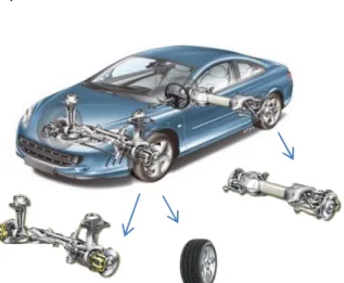
The same methods can be used to separate the contributions of front and rear axles when rolling on different tracks. Uncorrelation assumptions are not necessarily obvious in particular regarding front and rear wheel on the same side. This separation can also be done on roller test bench equipped with gravelled coating. It has advantages in terms of reproducibility, ease of implementation, but serves primarily to push the analysis further by breaking down the system. Thus, an axle or a tire/wheel fixed on specific test rig can be placed on the roller bench which is not feasible on track
.
Figure 1: Vehicle decompositions for road noise
This decomposition of a complex system into several subsystems easier to design is the foundation of System Engineering. For most of low frequency NVH problems, this decomposition is usually based on a vector summation involving forces and transfer functions in the form ([3]):
i ji i
j T f
p =
∑
(1)where Tij is a transfer function (or Frequency Response Function) between the acoustic pressure at the observation point j, pj, and the applied force fi, where index i denotes the excitation point and the direction of excitation.
If the two subsystems are loosely coupled, the forces depend only on the first system (eg the front axle) and the transfer functions on the second (eg car body). These decoupling conditions are completely filled between powertrain and car body but are less respected for suspensions and car body, and even less for tire-wheel and the rest of the vehicle. This has implications when analysing the results.
Moreover, such decompositions are usually done considering in-phase excitations and specific developments detailed in this paper are necessary to deal with random excitations.
Finally, difficulties due to different coatings selected by tire and car manufacturers should be noted. This matter requires specific cross measurements.
2
Decomposition methods
2.1
Methods available
Let us consider the general case of a system divided into two subsystems. Excitation is applied to the first system (eg the tire wheel excited by the coating). It is connected to a second system through an interface (for example, the junction between the wheel and the spindle). The goal is to decompose the participation of the two systems to the observed response on the system 2 (eg noise in the cabin). This requires to isolate a finite number of degrees of freedom for excitation (indexed e), interface (indexed i) and observation (indexed o). The first system is subjected to excitation and interface forces and the second one just to interface forces.
Figure 2: General case for system decomposition At each frequency, responses on each subsystem can be expressed by defining transfer function as:
(
)
) ( ) ( ) ( ) ( ) ( ) ( ) ( ) ( ) ( ) ( 2 1 2 2 1 2 1 1 ω ω ω ω ω ω ω ω ω ω → → ⎟ ⎟ ⎠ ⎞ ⎜ ⎜ ⎝ ⎛ = ⎟⎟ ⎠ ⎞ ⎜⎜ ⎝ ⎛ ⎟ ⎟ ⎠ ⎞ ⎜ ⎜ ⎝ ⎛ = i oi ii o i e i ie ii i F T T u u F F T T u (2)Where ω is the pulsation, ui and uo displacements (or pressures) at the interface and the observation points, Fe excitation force, Fi2→1 and Fi1→2interface force of one system on the other, and Tii1, Tie1, Tii2, Toi2 the frequency response functions of system 1 or 2 between the subscripted indices.
To simplify notations, pulsations are omitted in the following. Forces at the interface acting on each subsystem are classically designated as operational forces and depend on both subsystems. Equilibrium at the interface leads to:
(
ii ii)
ie ei i
i F F T T T F
F1+2= 1→2 =− 2→1= 1+ 2 −1 1 (3) Response at observation points can be expressed in a rather simple way:
2 1 2 + = oi i o T F u (4)
The response is decomposed in a transfer function only depending on second subsystem and operational forces which involve both subsystems. These forces depend only on the first subsystem if the decoupling condition is verified: 1 2 ii ii T T << (5)
Under this condition, operational forces become blocked forces defined by:
( )
ii ie ei T T F
F1= 1 −1 1 (6)
For road noise, blocked forces can be measured on a roller bench and they only depend on tire-wheel. The decoupling condition (5) is not verified and an alternative form of (4) can be used introducing transfer functions of the whole system:
(
1 2)
1 1 2 2 1 ii ii ii oi oi T T T T T + = + − (7)Response at observation points is then given by: 1 2 1 i oi o T F u = + (8)
Once again, this formulation is not fully satisfactory regarding system engineering as transfer functions depend on both subsystems.
The only expression with terms only depending on one subsystem is as follows:
(
1 2)
1 1 1 2 i ii ii ii oi o T T T T F u = + − (9)Using this formula to decompose the road noise at the centre wheel requires the measurement of blocked forces and impedances at the centre wheel for the tire-wheel, and the measurement of impedances and transfer functions for the rest of the vehicle. These measures need to be done in
operating conditions i.e. rolling under loading and are not easily feasible. Even if, an experimental characterization of each part, the tire wheel assembly and the car body, can be made as mentioned in [7], especially if rolling effects are neglected on the car body, the decomposition in (8) has been chosen for our study.
2.2
Signal processing of roller bench
measurements
Signal processing performed on roller bench measurements has been detailled in [3]. In particular, to avoid the roller bench to generate a periodic excitation, the vehicle speed is slowly increased over a range of about 10 km/h to get a random excitation signal. Continuous measurements are made and analyzed by computing the associated cross-spectral density matrix.
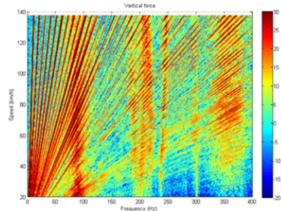
Figure 3: Vertical force measured on a roller bench When noise is decomposed through forces and transfer functions, the first check is to compare the reconstructed noise and the noise measured directly placing the entire vehicle on the bench. Therefore, the defined process must apply to tire-wheel blocked forces and noise measured in the cabin. Cross spectral density matrix are calculated between interface degree of freedom (and is denotedGFF) and also between observation point in the cabin (denoted
pp
G ).
The relationship between the two is given by the transfer functions in the form:
* pF FF pF pp T G T G = (10)
As detailed in [3], a principal component decomposition of the cross spectral matrix GFF allows working with fully uncorrelated excitations Ckat wheel centre:
∑
= = n k k k FF C C G 1 * .2.3
Interface definition
From a mechanical point of view, we must define the parts between which forces have to be calculated. These parts are the wheel and the hub so the mechanical interface is defined by the bearing face of the wheel on the hub. This interface can be considered rigid for frequency below 400Hz and 6 degrees of freedom are sufficient to characterize the interface. Another solution would be to consider the interface between the tire and the rim but the wheel is not rigid in the frequency band used. A third
would be to calculate the forces at the interface between the bearing and the knuckle but it would imply differences between front and rear axles.
Figure 4: Interface definition
Torques measured at the interface are calculated at the geometric position of the centre wheel defined as the intersection of rotation axis and wheel median plane. This position is more natural regarding tire symmetry.
3
Measurement of tire-wheel blocked
forces
3.1
Bench requirements
To measure tire-wheel blocked forces, test bench should ensure vehicle load leaving the wheel to turn freely. Forces must be measured close to the interface and test fixture need to be rigid compared to tire-wheel (decoupling condition (5) must be filled). Two examples of such devices are shown below:
Figure 5: Devices to measure tire-wheel blocked forces This measure is particularly difficult as shown in references [4], [5], [6]. The dynamic stiffness of the tire-wheel is large and exhibits peaks associated with its modal behaviour. Its vertical stiffness and rotational stiffness along longitudinal direction are compared to equivalent test fixture characteristics on Figure 6 and Figure 7.
Figure 6: Comparison of tire-wheel and test fixture vertical stiffness
In vertical direction, condition (5) is pretty well filled below 300Hz. Regarding rotational stiffness along longitudinal direction, the condition is respected up to 150Hz. Alloy and steel wheels exhibit different modal behaviour in this direction. The first bending mode of the studied steel wheel is located at 215Hz whereas for the alloy wheel, it is placed at 350Hz. Therefore, the quality of recomposition may be affected by those results at different frequencies for steel and alloy wheels.
Figure 7: Comparison of tire-wheel and test fixture rotational longitudinal stiffness in standing condition Special attention should be paid on rotational stiffness and even though it is hard to respect decoupling condition (5) up to 400Hz.
3.2
Tire-wheel blocked forces comparison
The tire-wheel blocked forces, as mentioned in (6) are the results of tire-wheel transfer functions and external forces applied to tire wheel assembly. For structure borne road noise, the external forces are generated by the tire/ground interaction. In order to compare the measurements performed by each partner, a first step consist in checking the excitation level generated by each rough surface for the same tire wheel assembly. We have employed some techniques describes in [8] to evaluate the excitation level of each ground. Even if the macro roughness estimated by road profile are different (Figure 9a and 9b), the indentation level characterized by enveloped profile on a loaded inflated tire wheel assembly are close.
(a) (b) Figure 8: Road surfaces
In order to check that fact, the same tire wheel assembly was measured on two roller benches equipped with their own ground surfaces. The blocked forces at wheel center are similar up to 200Hz. Some discrepancies are observed in medium frequency band due to specific interferences between tire wheel assembly and tire test rigs. (Figure n°10 and n°11)
Figure 9: Vertical force measured by tire and car manufacturer in rolling condition
Figure 10: Longitudinal torque measured by tire and car manufacturer in rolling condition
4
Measurement of vehicle transfer
functions
4.1
Measurement conditions
Besides measuring blocked forces, reconstruction noise according to the expression (8) requires the measurement of vehicle transfer functions between the wheel centre in 6 directions and observation points in the cabin.
The wheel centre as defined in paragraph 2.3 is not directly accessible and it is difficult to excite interface with a pure torque. Therefore, transfer functions must be reconstructed from several indirect measurements using a least squares minimization method.
The rolling of the tire changes its properties and its vibrational behaviour. In particular, gyroscopic and centrifugal effect cause a separation of frequency peak with speed (such phenomena can be seen on Figure 3). Thus, transfer functions should be measured at different speeds but on a perfectly smooth coating.
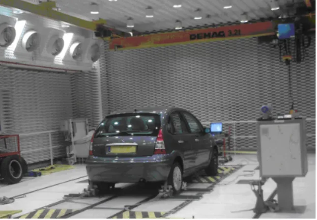
Figure 11: Roller bench used for transfer function measurement
Unfortunately, non-uniformity of the tire-wheel assembly disrupts these measurements at high speed and they have been performed only at low speed. The development of a specific protocol to measure these transfer functions in true rolling conditions is a tough question.
4.2
Tire-wheel effects on transfer
functions
One way to assess the coupling between the tire-wheel and the rest of the vehicle is to focus on the effect of changing the wheel or the tire on the transfer functions. If the decoupling condition (5) is verified, then it should have no effect and tire-wheel and the influence of tire-wheel will be only in tire-wheel blocked forces.
Figure 12 shows the differences between 2 tires on a transfer function. These tires have quite close definitions but transfer functions are pretty much the same.
Figure 12: Tire influence on a transfer function On Figure 13, the transfer functions are measured with a steel wheel and an alloy wheel. The differences are important even at low frequencies. To evaluate the effect of the wheel on road noise, it is necessary to know its effect on transfers function and blocked forces. Decoupling condition (5) between tire-wheel and the rest of the vehicle is not filled.
Figure 13: Wheel influence on a transfer function
5
Road noise decomposition
5.1
Direct vs reconstructed noise
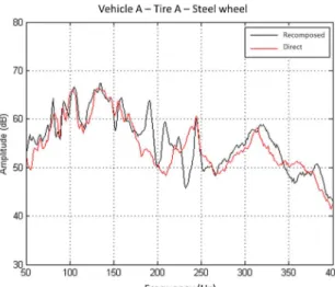
To assess the quality of the reconstructed the noise, the quadratic sum of the pressures measured at driver and passengers ears is calculated. Then direct and recomposed results are compared for each axle of different vehicle with different wheels. The frequency spectra are shown in Figure 14, Figure 15 and Figure 16.
Figure 14: Quality of reconstruction in case 1 Discrepancies beyond 150Hz can be explained by the lack of rigidity of the test bench as discussed in paragraph 3.1. For the steel wheel on Figure 15 differences appear around 200Hz while for alloy wheels they happen upon 250Hz. This is consistent with the bending frequencies observed on these wheels.
Figure 15: Quality of reconstruction in case 2 However, differences are visible in the Figure 16 around 120Hz and can’t be explained by test bench rigidity. It seems that they are due to measurement conditions of the transfer functions. Gyroscopic effects are responsible for the split in frequency of tire-wheel modes. These splits are correctly taken into account in tire-wheel blocked forces but not in transfer functions (as they are measured at low speed). This can lead to important errors even at low frequencies. Nevertheless, being aware of these limitations, the results are good enough to analyse transmission paths.
Figure 16: Quality of reconstruction in case 3
6
Transmission paths
According to formula (1) reconstructed noise can be decomposed along the different degrees of freedom at the wheel centre. As the wheel is free to roll, the torque in y direction is null.
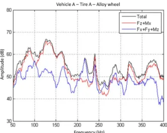
Results obtained by such analysis on one vehicle equipped with alloy wheel are shown on Figure 17. The trusted zone is given by the comparison between direct and reconstructed noise on Figure 14 and is restricted to frequencies below 250Hz.
Figure 17: Transmission paths
In the range [50-200Hz], noise is mainly due to vertical force and longitudinal torque. The 2 rather sharp peaks between 200 and 250Hz are caused by tire cavity resonances and all directions are involved.
7
Conclusion
A method has been chosen and implemented to decompose structure-borne road noise at the wheel centre in order to assess tire/wheel and vehicle effects. It has been performed jointly by a car and a tire manufacturer.
The decomposition used is based on the measure of tire-wheel blocked forces and transfer functions from the tire-wheel centre to driver and passengers ears. The 2 systems associated with this interface are highly coupled and the transfer functions strongly depend on tire-wheel definition.
Specific treatments for measurements on roller bench are applied both for blocked forces and pressures measured directly in the cabin. The comparison of test fixture (used for blocked force) and tire-wheel stiffness exhibits some limitations especially regarding wheel bending modes. The fact that the transfer functions are not measured at operational speed is also a source of difference because frequency splits due to gyroscopic effects are not taken into account.
Considering all these limitations, direct and recomposed noises are close enough to analyse transmission paths.
Nevertheless, to overcome limitations due to the coupling between tire-wheel and vehicle, we suggest applying the formulae (9) as mentioned in [7]. In that case, the vehicle will be evaluated one time and the rotating effects will be included in tire wheel characterisations.
Acknowledgments
The authors would like to thank their colleagues that were involved in this job.
For PSA Peugeot Citroën: O. Méchin, T. Muot, L. Gagliardini, Z. Abbadi
For Michelin : D. Le Pen, D. Rochoux, M. Duvernier
References
[1] J.S. Bendat, A.G. Piersol, Engineering applications of correlation and spectral analysis, Wiley Interscience Ed., New-York.
[2] L.G. Hartleip, T.J. Roggenkamp, Case study : Experimental determination of airborne and structure-borne noise spectral content on passenger vehicle, SAE Noise and Vibration Conference, Traverse City, MI (2005).
[3] A. Gaudin, L. Gagliardini, Recent improvements in road noise control, SAE Noise and Vibration Conference, St Charles, IL (2007).
[4] J. Park, P. Gu, Operational spindle load estimation methodology for road NVH applications, SAE Noise and Vibration Conference, Traverse City, MI (2001). [5] J. Park, P. Gu, A new experimental methodology to
estimate chassis force transmissibility and application to road NVH improvement, SAE Noise and Vibration Conference, Traverse City, MI (2003).
[6] J. Park, P. Gu, M.R. Lee, A. Ni, A new experimental to estimate tire/wheel blocked force for road NVH application, SAE Noise and Vibration Conference, Traverse City, MI (2005).
[7] JF Beniguel and al, Method for predicting the noise comfort performance of a vehicle travelling on uneven ground, Patent W0 2009/133113 A1
[8] D Rochoux, F Biesse, Tire/road noise, the tire vibration as the main noise source from road texture, Inter Noise 2010, Lisbon, Portugal (2010)