ARCHITECTING AN LTE BASE STATION WITH GRAPHICS PROCESSING UNITS
Q. Zheng
∗, Y. Chen
∗, R. Dreslinski
∗, C. Chakrabarti
†, A. Anastasopoulos
∗, S. Mahlke
∗and T. Mudge
∗ ∗EECS Department, University of Michigan, Ann Arbor
†
School of ECEE, Arizona State University, Tempe
ABSTRACT
Due to the rapid growth of mobile communication, wireless base stations are becoming a significant consumer of compu-tational resources. Historically, base stations have been built from ASICs, DSP processors, or FPGAs. This paper studies the feasibility of building wireless base stations from com-mercial graphics processing units (GPUs). GPUs are attrac-tive because they are widely used massively parallel devices that can be programmed in a high level language. Base sta-tion workloads are highly parallel, making GPUs a potential candidate for a cost effective programmable solution. In this work, we develop parallel implementations of key kernels to evaluate the merits of using GPUs as the baseband signal pro-cessor. We show that the digital processing subsystem for a 75 Mbps LTE base station can be built using two NVIDIA GTX 680 GPUs with power consumption of 188 W.
Index Terms— LTE base station, baseband processing, graphics processing unit, power efficient
1. INTRODUCTION
Over the last decade more and more people have been using mobile devices to connect anywhere anytime. Applications supported by these devices, such as web browsing and real-time gaming, require high data rates. To address these needs, third (3G) and fourth (4G) generation wireless technologies have been deployed.
3GPP Long Term Evolution (LTE) is a standard for 4G wireless communication of high-speed data for mobile phones and data terminals. LTE is designed to increase the cell capacity and provide high data rate and is expected to support up to four times the data and voice capacity sup-ported by HSPA [1]. LTE can achieve a peak data rate of 75 Mbps for uplink and 150 Mbps for downlink. In multiple antenna configurations the peak data rate for downlink can be as high as 300 Mbps.
A wireless base station is responsible for coordinating the traffic and signaling between mobile devices and the network switching system, making them an integral part of the cellular network. Baseband processing requires giga-operations-per-second level throughput [2], making it one of the most
com-THIS WORK IS SUPPORTED BY NSF-CNS-0910851 AND ARM.
putationally intensive components of a base station. Further complicating baseband processor design is the requirement that they must also support multiple wireless communication protocols. This makes the cost of a fixed application-specific integrated circuit (ASIC) solution more costly and drives the need for a programmable solution.
To support easy migration to newer and updated stan-dards, a base station should be built with programmable pro-cessors that provide high throughput and low power. While some commercial DSPs [2–4] provide a good tradeoff be-tween throughput and power consumption, they have to be integrated with accelerators, often designed by different com-panies, to implement a baseband system. Alternatively, a general-purpose processor has been shown to be a viable solution for CDMA with full programmability and good portability [5]. Unfortunately, this solution is costly because of the large number of Intel Xeon processors that are required. In this paper we explore building an LTE base station
with graphics processing units. These processors provide
GFLOPS-level throughput, and have high compute capabil-ity per Joule [6]. GPUs also have added language support like CUDA for general purpose programming. They provide programmers the ability to exploit high degrees of data-level parallelism (DLP) and thread-level parallelism (TLP). Thus, GPUs are ideal architectural platforms for LTE baseband pro-cessing where DLP and TLP are abundant. In addition, due to their high raw compute power per dollar, GPUs are very cost-efficient solutions.
In this work we demonstrate how the digital baseband sys-tem for an LTE base station can be built with commercial GPUs. We develop highly parallel GPU implementations of all key kernel algorithms in LTE baseband processing, and study their runtime performance under different antenna con-figurations and modulation schemes when implemented on a NVIDIA GTX680 GPU. In this paper, we explore a multi-GPU configuration for high data rate applications. Finally, we estimate the power consumption by measuring the dy-namic power of each kernel running on a GTX680 GPU. For a 75 Mbps LTE baseband uplink, the digital subsystem of our dual-GPU based LTE base station consumes 188 W, which is competitive with commercial systems.
The rest of the paper is organized as follows. Section 2 introduces the background information of baseband
process-RF SC-FDMA Demodulation MIMO detector Ant 1 Ant 1 data Ant 1 data Ant N data . . R e so u rce e le me n t D e ma p p e r Channel Estimation Ant N data Ant 1 pilot Ant N pilot ⋮ ⋮ ⋮ ⋮ RF SC-FDMA Demodulation Ant N Transform decoder P/S Channel decoder Descrambling R a te m a tc h e r Modulation demapper
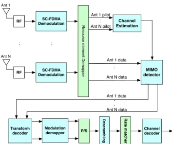
Fig. 1: Baseband processing of the receiver in an LTE base station
ing in an LTE base station. The GPU implementations of key kernels are described in section 3. Section 4 shows the kernel runtime performance, the minimum number of needed GPU under different system configurations, and the power consumption. Related work is discussed in section 5 and the paper is concluded in section 6.
2. BASEBAND PROCESSING IN AN LTE BASE STATION
The main baseband processing kernels in an LTE base station receiver are shown in Fig 1. LTE uplink uses Single Carrier Frequency Division Multiple Access (SC-FDMA) for trans-mission [7]. The total number of subcarriers is fixed based on how much radio bandwidth is used. When there is more than one user, the subcarriers are shared, thereby lowering the data rate for each user. The received data from the channel is first processed through SC-FDMA FFT. Pilot signals are used to estimate the channel state information (CSI), which is then used in the MIMO detector to counteract the effects of the channel. The transform decoder performs IDFT on the equal-ized data. The modulation demapper retrieves bits by gen-erating soft information, and the descrambling reorders soft information based on a predefined pattern. The rate matcher punctures soft information into a predefined length, and fi-nally the Turbo decoder recovers binary information bits. We give a brief description of the key kernels below.
SC-FDMA: SC-FDMA is a precoded Orthogonal Fre-quency Division Multiplexing (OFDM) scheme, which has an additional transform decoding step after conventional OFDM processing. In the LTE uplink receiver, the OFDM step is done using FFT, and the transform decoding step is done us-ing a mixed radix IDFT. The largest size of OFDM FFT is 2048, and that of transform decoding IDFT is 1200.
Channel estimation: The LTE uplink transmission uses the comb-type pilot arrangement. Channel estimation takes the received signal and known pilot reference symbols to esti-mate the CSI, and then computes the channel coefficients. We implemented frequency domain least square channel estima-tion [8].
MIMO detector: MIMO technology is the use of mul-tiple antennae at both the transmitter and the receiver with the aim of increasing performance and/or data rate. There are various MIMO detection methods, such as equalization-based detection, sphere decoding and lattice reduction detec-tion. For LTE uplink, an equalization-based MIMO detector, such as zero-forcing (ZF) and minimum mean-square error (MMSE) equalizer, is usually used. We used the MMSE-based MIMO detector in our GPU implementation.
Modulation demapper: The goal of the modulation mapper is to represent a binary data stream with a signal that matches the characteristics of the channel [9]. The binary sequences are grouped and mapped into complex-valued con-stellation symbols. The modulation demapper, on the other hand, retrieves the binary stream from the signal by generat-ing either hard or soft information. LTE uplink supports four different schemes: BPSK, QPSK, 16QAM and 64QAM. We implemented a soft decision modulation demapper.
Turbo decoder: Turbo codes are used for channel cod-ing in LTE. The Turbo decoder architecture includes two Soft-Input-Soft-Output (SISO) decoders and one internal in-terleaver/deinterleaver. Inside each SISO decoder, a forward and backward trellis traversal algorithm is performed. The Turbo decoder works in an iterative fashion. For our GPU implementation, we set the number of iterations to be 5.
3. IMPLEMENTATION OF KEY KERNELS ON GPU 3.1. Implementation of kernels on the physical layer
State-of-art GPUs, such as NVIDIA GTX680, can launch thousands of threads at the same time. So an efficient imple-mentation of kernels on a GPU involve exploiting parallelism at all levels so that enough number of threads are created to keep GPUs busy. There are several types of parallelism in the physical layer kernels: user-level, antenna-level, symbol-level, subcarrier-level and algorithm-level. The different types of parallelism are orthogonal to each other, and can be used at the same time to achieve a better GPU utilization.
User-level ParallelismA base station serves several users si-multaneously, and the signal processing that is done for each user data is independent from others after some initial joint processing at least. Therefore, a kernel can process data from different users at the same time. The number of generated threads is the same as the number of users.
Antenna-level ParallelismData received by the different an-tennae in the uplink receiver can be processed simultaneously until they reach the transform decoder. Therefore, in these
instances, the number of threads is equal to the number of receiver antenna.
Symbol-level ParallelismThe operations of a kernel for a subframe can be parallelized by processing SC-FDMA sym-bols in a subframe at the same time. The number of threads is as many as SC-FDMA symbols in a subframe.
Subcarrier-level ParallelismWe assume the subcarriers are evenly distributed among all users. Each subcarrier in an SC-FDMA symbol of each user is independent, and can be cal-culated in parallel. The number of threads is the same as the number of subcarriers.
Algorithm-level ParallelismThere is parallelism inherent in each algorithm, and it varies based on the kernel. For example in FFT, the operations in the nodes of each butterfly stage can be done in parallel.
In order to show the parallelism of each physical layer kernel, we define the following:
• NF T – FFT/IFFT size
• NT x×NRx– antenna configuration
• NM od– number of points in a modulation constellation
• Nsub– number of subcarriers in a symbol per user
• Nsym– number of symbols in a subframe
• Nusr– number of users
SC-FDMA: The primary operations in SC-FDMA are FFT and IFFT. To map FFT and IFFT efficiently onto a GPU, we employed user-level, antenna-level, symbol-level and algorithm-level parallelism. In FFT/IFFT, in each stage, the butterfly nodes can be processed independently. So the num-ber of threads created from algorithm-level parallelism is the same as the FFT/IFFT size. The total number of threads that can be generated for FFT/IFFT isNusr×NRx×Nsym×NF T. In this study, we used cuFFT for the GPU implementation of FFT/IFFT. CuFFT is a CUDA library provided by NVIDIA for computing FFT/IFFT with the input sizes in the form of
2a ×3b×5c×7d [10]. We can employ all four levels of parallelism by using cuFFT: the FFT/IFFT implementation of cuFFT exploits the algorithm-level parallelism, and we make use of the other types of parallelism by batching multiple FFT/IFFT computations.
Channel estimation: We implemented a least square based frequency domain channel estimation unit. User-level, antenna-level and subcarrier-level parallelism are consid-ered. The total number of threads that can be generated is
Nusr×NRx×Nsub.
MIMO detector: We mapped an MMSE-based MIMO detector on the GPU. We considered user-level, symbol-level and subcarrier-level parallelism. The total number of threads that can be generated for MIMO detector isNusr×Nsym×
Nsub.
Modulation demapper: Modulation demapping of a subcarrier value consists of two parts: metric calculation and likelihood ratio computing. For metric calculation, we computed the Euclidean distances between the subcarrier value and all complex values in the mapping constellation as the metrics. Algorithm-level parallelism results in as many threads as points in the constellation mapping for a subcarrier. For the logarithm likelihood ratio part, the number of threads is the same as the number of bits in a
bit sequence. For example, QPSK groups two bits in a
bit sequence and maps the sequence to a single value in the constellation, and two threads are created for each sub-carrier in this case. For metric calculation and likelihood ratio computing, the total number of threads that can be
generated is Nusr ×Nsym ×Nsub ×NRx ×NM od, and
Nusr×Nsym×Nsub×NRx×log2(NM od), respectively. Table 1 summarizes the number of threads that can be cre-ated for each kernel. In our implementation using NVIDIA GTX680 GPU, we were able to generate all the threads, re-sulting in very high GPU utilization.
Table 1: Number of threads in PHY layer kernels
Kernel Number of Threads
FFT/IFFT Nusr×NRx×Nsym×NF T
Channel
estimation Nusr×NRx×Nsub
MIMO
detector Nusr×Nsym×Nsub
Modulation Nusr×Nsym×Nsub×NRx×NM od
demapper Nusr×Nsym×Nsub×NRx×log2(NM od)
3.2. Turbo decoder
For the Turbo decoder, we consider algorithm-level paral-lelism in the form of codeword-level, subblock-level and trellis-level parallelism [11]. We include a brief introduction here, a more detailed description can be found in [11].
Codeword-level ParallelismThe codewords can be stored in a buffer so that they can be decoded in parallel. Using codeword-level parallelism results in long latency especially for the first codeword in the buffer.
Subblock-level ParallelismA codeword can be divided into several subblocks, which are processed in parallel. This leads to a higher bit error rate, because the computations in the sub-blocks are not independent of each other. The performance loss can be compensated by employing recovery algorithms. There are two widely used algorithms: training sequence (TS) and next iteration initialization (NII). From an implementa-tion perspective, TS requires addiimplementa-tional operaimplementa-tions, and NII needs additional memory.
Trellis-level ParallelismIn the trellis of Turbo code, we can parallelize the Turbo decoder by exploring state-level paral-lelism, forward-backward traversal (FB) and branch-metric parallelism (BM). State-level parallelism, in which the nodes
in a stage are processed in parallel, does not affect BER. FB leads to more complex index and memory address computa-tions, thereby lowering the throughput. BM is not as effective since the vector reduction parts cannot be parallelized.
To summarize, trellis-level parallelism improves through-put without impairing latency and BER. Codeword-level and subblock-level parallelism improve throughput at the cost of either longer latency or higher BER. Both recovery schemes degrade the throughput but improve BER performance com-pared to only subblock-level parallelism.
4. RESULTS 4.1. Experimental Environment
We used an NVIDIA GTX680 GPU to evaluate the perfor-mance of the key kernels. GTX680 is based on the Kepler architecture [12]. It has 8 Streaming Multiprocessors (SMX), and in each SMX there are 192 Streaming Processors clocked at 1GHz. A GTX680 GPU can launch at most 1024 threads at a time. There is a 64 KB on-chip memory, a 512 KB L2 cache and 2048 MB external memory. To monitor the GPU, we used GPU-Z, which is a lightweight tool designed to pro-vide information such as the dynamic power consumption, the dynamic GPU load, the fan speed, etc. To launch GPU ker-nels, we used a 2.13 GHz Intel Core 2 processor, running the Linux 3.2.0-39 generic operating system.
In this study, we simulated a fading channel with addi-tive white Gaussian noise. We evaluated kernel implementa-tion performance corresponding to peak data rate. We also focused on the single-user scenario because it gives a worst case estimate of the GPU performance, due to the lack of par-allelism presented by multiple users. In this operating sce-nario, the computations in a base station depend on the total number of available subcarriers.
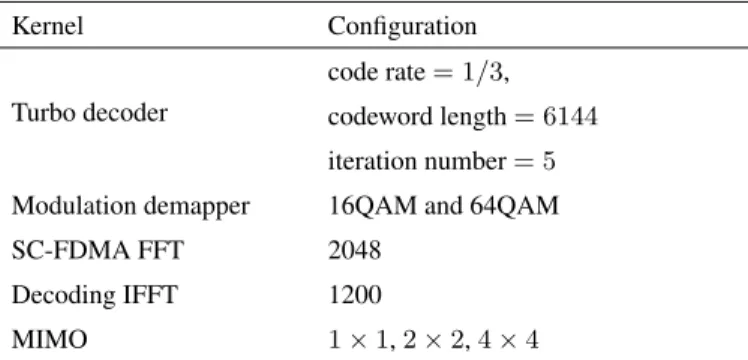
Table 2: The configurations of kernels
Kernel Configuration
Turbo decoder
code rate= 1/3,
codeword length= 6144
iteration number= 5
Modulation demapper 16QAM and 64QAM
SC-FDMA FFT 2048
Decoding IFFT 1200
MIMO 1×1,2×2,4×4
4.2. Kernel Runtimes
We ran each kernel for the different configurations shown in Table 2. Table 3 shows the runtimes of different physical layer kernels of an LTE subframe. It demonstrates that modulation
Table 3: PHY layer kernel runtimes (ms) of an LTE subframe
Antenna configuration 1×1 2×2 4×4 FFT 0.06 0.07 0.08 IFFT 0.10 0.10 0.10 MIMO detector 0.02 0.03 0.52 Channel estimation 0.02 0.05 0.46 Modulation 16QAM 0.08 0.15 0.28 demapper 64QAM 0.47 0.92 1.81
demapping takes the longest runtime. In addition, MIMO de-tection, channel estimation and modulation demapping have fairly long runtimes when more antennae or more complex modulation schemes are used.
Table 4: Performance of Turbo decoder implementations
Schemes TH1 WPL1 BER1,4 TL2 Subblock Num CW1 Num (Mbps) (ms) SL2 512 2 77.64 0.72 1.6×10⁻³ SL 256 4 78.15 1.68 4.1×10⁻⁴ SL,FB2 256 2 78.30 0.72 4.1×10⁻⁴ SL,FB 128 7 80.58 3.08 2.0×10⁻⁴
1TH = Throughput, WPL = Worst-case codeword Latency, SNR =
Signal-to-Noise Ratio requirement, BER = Bit Error Rate, CW = Codeword
2TL = Trellis-level parallelism, SL = State-level parallelism, FB =
Forward-Backward traversal
3BER here is the bit error rate when SNR = 1.0 dB
For the Turbo decoder, we tried combinations of differ-ent parallelization schemes to find the best tradeoff among the decoding throughput, worst-case latency and BER [11]. Table 4 shows the performance of the Turbo decoder imple-mentations. It demonstrates that the implementation in row 3 achieves the best tradeoff. We use this implementation in the rest of the paper.
Our implementation of kernels exploits the parallelism at multiple levels. For instance, in our GPU implementation
of a 4 ×4 64QAM system, there are 14,336 threads
cre-ated for FFT,4,800 threads for channel estimation,14,400
threads for MIMO detection, 3,686,400 threads for mod-ulation demapping metric calcmod-ulation, 345,600 threads for modulation demapping likelihood ratio computing, and8,192
threads for the Turbo decoder. Because an NVIDIA GTX680 GPU can launch at most1,024threads at a time, it is almost always fully utilized.
4.3. GPU-based LTE Baseband System
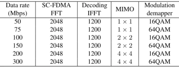
A baseband processor must meet the latency and throughput requirements of the communication protocol. LTE supports multiple data rates up to 300 Mbps. Table 5 describes the kernel configurations for the different data rates. For high
data rates, the computational load of LTE baseband process-ing is very high and a sprocess-ingle GPU is not enough. For in-stance, to process a subframe of 1ms, the sum of runtimes of all kernels on PHY layer can be no larger than 1 ms. Based on runtimes presented in Table 3, one GPU is not enough to meet this requirement for high data rates when multiple anten-nae or more complex modulation schemes are used. In such cases, we assign the processing of subcarriers in a symbol onto multiple GPUs. Assuming that the subcarriers are allo-cated evenly among GPUs and that Turbo decoding is done by a separate set of GPUs, we estimate the minimum num-ber of GPUs needed to meet the 1ms deadline under different system configurations. Table 6 shows the minimum number of GTX680 GPUs needed for PHY layer processing and the Turbo decoder. This analysis shows that for a 75 Mbps data rate, two GPUs are needed–one for processing the physical layer kernels and one for the Turbo decoder. When the peak data rate is higher, 100 Mbps, two GPUs are needed for the Turbo decoder. This is because a single GPU can only sup-port Turbo decoder up to a 78 Mbps data rate. The GPUs are connected through PCI-Express on a board with low commu-nication latency. A commercial motherboard can support up to four GPUs [13]. When more GPUs are required for higher data rates, multiple boards have to be interconnected through Ethernet, which leads to longer latency.
Table 5: Kernel configurations for different peak data rates Data rate (Mbps) SC-FDMA FFT Decoding IFFT MIMO Modulation demapper 50 2048 1200 1×1 16QAM 75 2048 1200 1×1 64QAM 100 2048 1200 2×2 16QAM 150 2048 1200 2×2 64QAM 200 2048 1200 4×4 16QAM 300 2048 1200 4×4 64QAM
Table 6: The minimum number of GTX680 GPUs needed for the baseband system covering a cell
Data rate Number of GPUs
(Mbps) PHY Turbo Total
50 1 1 2 75 1 1 2 100 1 2 3 150 2 2 4 200 2 3 5 300 5 4 9 4.4. Power Consumption
We measured the dynamic power consumption of the LTE kernels using GPU-Z. Table 7 shows the power consumption of each kernel and the corresponding configuration. We also
measured the power consumed by each kernel under different configurations, and observed very limited variation. The ac-tual energy consumed by each kernel is presented in Table 8. It shows that the Turbo decoder consumes most of the system energy followed by modulation demapper.
Table 7: Power of each kernel on a GTX680 GPU
Kernel Configuration Power
(W)
Turbo decoder Row 3 in Table 4 63.3
SC-FDMA FFT 2048 56.7
Decoding IFFT 1200 56.9
Modulation demapper 64QAM 56.3
Channel estimation - 61.8
MIMO detector 4×4 57.7
For a system-level power assessment, we considered the configuration corresponding to a 75 Mbps data rate. Based on Table 6, we need two GTX680 GPUs for a 75 Mbps data rate, one for the Turbo decoder and the other for the PHY layer. We also need one Intel Core 2 CPU, whose maximum power is 63 W. Thus, the total power of the digital subsystem of the receiver is 188 W. We compared it with the Alcatel-Lucent 9926 Base Band Unit [14] whose maximum power is 370 W with 74 Mbps peak uplink throughput. While 370 W includes both the transmitter and receiver power, the receiver processes more complex kernels, like Turbo decoding and MIMO detec-tion, and consumes a significantly larger portion of the com-pute power. Even if we conservatively estimate that half of the power, 185 W, is consumed by the receiver, then our proposed GPU-based solution is still quite competitive.
Table 8: Energy consumption of each kernel processing 1 subframe at 75Mbps on a GTX680 GPU
Kernel Energy (mJ/subframe)
Turbo decoder 144.0 SC-FDMA FFT 3.4 Decoding IFFT 5.7 Modulation demapper 26.5 Channel estimation 1.2 MIMO detector 1.3 5. RELATED WORK
GPU-based solutions: The GPU implementation of the transmitter in an LTE base station was presented in [15]. In contrast, we provided the GPU implementation of the receiver along with a detailed analysis of possible paralleliza-tion schemes and their effectiveness.
DSP-based solutions: There are several DSP-based so-lutions. Freescale’s Modular AdvancedMC Platform [3] con-tains three MSC8156 DSPs for baseband processing. Each
DSP has six StarCore SC3850, and a MAPLE-B baseband accelerator for Turbo/Viterbi decoder, FFT/IFFT, and
multi-standard CRC check and insertion [16]. CommAgility’s
AMC-3C87F3 is a signal processing card for 4G wireless
baseband. It contains three Texas Instruments’ TCI6487
DSPs, each with three C64x+ cores and coprocessors for Viterbi decoder, Turbo decoder and Rake search/spread.
Although the DSPs mentioned above are programmable, several key kernels are implemented using accelerators, which impairs the system flexibility. To support new pro-tocols, new accelerators have to be designed and integrated with DSPs, leading to a long development cycle and high cost. In contrast, GPU-based solutions only need new soft-ware for the system update, which dramatically reduces time-to-market and cost. Additionally, if GPUs cannot support the high data rate of future protocols, they can be replaced by newer and faster GPUs, provided these newer GPUs support a high level programming paradigm such as CUDA.
FPGA-based solutions:Xilinx [17] and Altera [18] have developed FPGA solutions for baseband processing in LTE base stations. Although FPGAs have good flexibility, their relatively high price increases the cost of using them to build a base station. A GPU-based base station has a fairly short development cycle and little updating effort, because the soft-ware is implemented in a relatively simple high-level lan-guage.
GPP-based solutions: The Vanu Anywave base sta-tion [5] is the only fully programmable commercial base station to date. It is built with 4-13 Intel MPCBL0040 single board computers [19] based on the required cell capacity. An MPCBL0040 computer contains two Dual-Core Intel Xeon E7520 2.0 GHz processors. The Vanu Anywave uses GPPs in-stead of DSP. Currently it supports GSM/EDGE/CDMA2000 but does not support LTE.
GPPs have good flexibility and portability, but they can-not make full use of the available DLP in a wireless base station. This is why Vanu needs as many as 52 Intel Xeon cores to support CDMA2000, and more are expected in order to support LTE, leading to even higher power consumption. A GPU-based solution takes advantage of massive DLP. So fewer GPUs are needed in an LTE base station, which makes a GPU-based solution power efficient.
6. CONCLUSION
In this paper, we presented our work on building a baseband system for an LTE base station using commercial GPUs. The kernels in LTE baseband processing are highly parallel,
and thus amenable to efficient GPU implementation. We
implemented key kernels of an LTE baseband system on an NVIDIA GTX680 GPU, and evaluated the runtime perfor-mance. We showed that an LTE base station that supports a 75 Mbps peak uplink data rate can be built by using two GPUs. To support higher uplink data rates, more complex
antennae and modulation schemes are needed. In these
sit-uations a dual-GPU solution is no longer sufficient. We
also showed that the GPU-based solution is power efficient. To support the digital subsystem of a 75 Mbps uplink, a dual-GPU LTE base station consumes 188 W, which is quite competitive with commercial solutions.
7. REFERENCES
[1] “Long Term Evolution (LTE),” White Paper, Motorola, Apr. 2011.
[2] “LTE emerges as early leader in 4G technologies,” White Pa-per, Texas Instruments, 2009.
[3] “Modular AdvancedMC Platform for Broadband/LTE Base Stations,” Freescale Semiconductor, 2010.
[4] CEVA-XC4000. [Online]. Available: http://www.ceva-dsp.
com/CEVA-XC4000.html
[5] “The Vanu Anywave Base Station Subsystem,” Vanu Inc., Apr. 2006.
[6] S. Huang, S. Xiao, and W. Feng, “On the Energy Efficiency of
Graphics Processing Units for Scientific Computing,” inIEEE
International Symposium on Parallel Distributed Processing (IPDPS’09), 2009, pp. 1–8.
[7] “Overview of the 3GPP Long Term Evolution Physical Layer,” White Paper, Freescale Semiconductor, Jul. 2007.
[8] S. Coleri and et al., “Channel Estimation Techniques based on
Pilot Arrangement in OFDM Systems,”IEEE Transactions on
Broadcasting, vol. 48, no. 3, pp. 223–229, 2002.
[9] J. G. Proakis and M. Salehi,Digital Communications, 5th ed.
New York, NY: McGraw-Hill, 2008.
[10] CUFFT User Guide. [Online]. Available: http://docs.nvidia. com/cuda/cufft/index.html
[11] Q. Zheng and et al., “Parallelization Techniques for
Imple-menting Trellis Algorithms on Graphics Processors,” inThe
IEEE International Symposium on Circuits and Systems (IS-CAS ’13), 2013.
[12] “NVIDIA GeForce GTX 680–The fastest, most efficient GPU ever built,” White Paper, NVIDIA.
[13] K. Spafford, J. Meredith, and J. S. Vetter, “Quantifying NUMA
and contention effects in multi-GPU systems,” inGPGPU-4
Proceedings of the Fourth Workshop on General Purpose Pro-cessing on Graphics ProPro-cessing Units, 2011, pp. 11:1 –11:7. [14] “Alcatel-Lucent 9926 Digital 2U eNodeB Baseband Unit,”
Product Brief, Alcatel-Lucent, 2009.
[15] S. Lee, C. Ahn, and S. Choi, “Implementation of Software-based 2X2 MIMO LTE Base station system using GPU,” in
SDR-WInnComm, 2011.
[16] “Product Brief: 4G (LTE/WiMAX) Base Transceiver Station AMC,” Accipiter Systems, 2010.
[17] “LTE Baseband Targeted Design Platform,” Xilinx, 2011.
[18] LTE Channel Card Solutions. [Online].
Avail-able: http://www.altera.com/end-markets/wireless/lte/
channel-card/wir-lte-channel-solution.html
[19] “Intel Solutions for the Next Generation Multi-Radio Basesta-tion,” Application Note, Intel, 2006.