Modeling Construction Equipment in 4D Simulation
and Application in VR Safety Training
Roya Amrollahibuki
A thesis In the Department of
Building, Civil, and Environmental Engineering
Presented in Fulfillment of the Requirements
For the Degree of Master of Applied Science (Building Engineering) at Concordia University
Montreal, Quebec, Canada
June 2019
ii Dr. Amin Hammad
Dr. Sang Hyeok Han Dr. Fereshteh Mafakheri
Dr. Osama Moselhi Dr. Osama Moselhi
CONCORDIA UNIVERSITY
School of Graduate Studies
This is to certify that the thesis prepared By: Roya Amrollahibuki
Entitled: Modeling Construction Equipment in 4D Simulation and Application in VR Safety Training
And submitted in partial fulfillment of the requirements for the degree of Master of Applied Science (Building Engineering)
Complies with the regulations of the University and meets the accepted standards with respect to originality and quality.
Signed by the final Examining committee:
_______________________________________ Chair _______________________________________ Examiner _______________________________________ Examiner _______________________________________ Examiner _______________________________________ Supervisor Approved by __________________________________________________ Chair of Departmental or Graduate Program Director
__________________________________________________ Dean of Faculty
iii
ABSTRACT
Modeling Construction Equipment in 4D Simulation and Application in VR
Safety Training
Roya Amrollahibuki
Enhancing safety and productivity in construction sites is of principal importance, especially in congested sites. Scheduling and visualizing the construction progress in a Four-dimensional (4D) model with a high Level of Detail (LOD) are expected to improve safety, productivity, and constructability in construction sites. In spite of the large number of studies using Building Information Modeling (BIM) for visualization of the construction activities at the macro-level, these research works do not fully consider the scheduling and animating the equipment operations at the micro-level. This study aims to visualize the construction equipment activities to model the erection of a structure with prefabricated components along with other resources, such as workers and temporary equipment. The construction process is modeled in Fuzor Virtual Design and Construction (VDC) and the collision test is run to find the upcoming dangers. In addition, one of the areas where 4D can be used is for safety training. It is expected that the combination of 4D BIM with Virtual Reality (VR) improves the safety knowledge of construction workers, students, and equipment operators. Despite the large number of research works on the use of Three-dimensional (3D) VR in construction training, 4D VR is not sufficiently used for training purposes. This study aims to improve the safety knowledge of construction students by using a VR-based training approach. The specific objectives of the research are: (1) Identifying the requirements for construction equipment modeling and comparing the available commercial and research platforms in terms of visualizing, animating, and simulating equipment movements; (2) Animating and scheduling the construction processes at the micro-level in 4D BIM; and (3) Enhancing and
iv
evaluating the safety knowledge of construction management students in terms of Personal Protective Equipment (PPE) and equipment-related hazards using VR. In the first stage, the construction 4D context was developed and the safety scenarios about PPE- and equipment-related hazards were added. Secondly, construction students were given the initial VR-based training regarding hazard scenarios. Then, their safety knowledge was tested and they were asked to express their learning experience.
The conclusions of this research are as follows: (1) When equipment tasks are visualized and scheduled at the micro-level in 4D BIM, the conflicts can be detected in advance and the cycle time of equipment can be determined, leading to the improvement of safety, productivity, and constructability in construction sites; (2) VR safety training improves hazard recognition of construction students since they can experience risky conditions in virtual construction sites; and (3) The capability of students in identifying equipment-related hazards would improve when they experience safety risks applied in 4D VR.
v
ACKNOWLEDGEMENT
Foremost, I would like to express my sincere gratitude to my supervisor, Dr. Amin Hammad for his support, encouragement, and patience. His guidance helped me at all stages of research and writing of this thesis. Without his support, I could not have made such progress in this research.
I appreciate my supportive lab mates who made the lab a pleasant and friendly environment for working and studying together. Besides, I thank Fuzor company and Erica Jamerson for helping me in the implementation of the case studies.
Last but not least, I would like to thank my supportive parents, Mina Amrollahi Buki and Alireza Amrollahi Buki and my brother Saeid for their endless love and encouragement.
vi
TABLE OF CONTENTS
ABSTRACT ... iii
LIST OF FIGURES ... ix
LIST OF TABLES ... xi
LIST OF ABBREVIATIONS ... xii
CHAPTER 1 INTRODUCTION ... 1
1.1 General information ...1
1.2 Problem statement ...2
1.3 Research objectives ...3
1.4 Thesis organization ...3
CHAPTER 2 LITERATURE REVIEW ... 5
2.1 Introduction ...5
2.2 Development trends of BIM ...5
2.2.1 3D and 4D applications in construction ... 6
2.2.2 4D applications in construction safety ... 8
2.3 Visualization of equipment activities in 4D ...8
2.3.1 Generation of construction equipment workspace ... 9
2.4 Virtual Reality (VR) and Augmented Reality (AR)...11
2.4.1 Definition and scope ... 11
2.4.2 Research trends of VR and AR in construction ... 13
vii
2.5 Summary and conclusions ...20
CHAPTER 3 PROPOSED METHODOLOGY ... 22
3.1 Introduction ...22
3.2 Proposed method for comparing equipment-related features of different tools ...23
3.2.1 Requirements for construction equipment modeling ... 24
3.3 Proposed method for generating articulated equipment ...31
3.4 A framework for using 4D VR for safety knowledge training ...34
3.4.1 Safety scenarios for training ... 35
3.4.2 Safety knowledge training ... 37
3.4.3 Safety knowledge testing ... 38
3.4.4 Learning experience evaluation ... 39
3.5 Summary and conclusions ...40
CHAPTER 4 IMPLEMENTATION AND CASE STUDIES ... 42
4.1 Introduction ...42 4.2 Comparison of tools ...43 4.2.1 3D animation software ... 43 4.2.2 4D BIM software ... 44 4.2.3 Game engine ... 47 4.2.4 Other applications ... 50
4.3 Visualizing articulated equipment and its workspace using 3D animation software ...52
4.3.1 Animating equipment movements ... 53
viii
4.4 First Case Study: Modeling and scheduling the construction progress in 4D BIM ...56
4.4.1 General Information ... 56
4.4.2 Resource allocation and animating the equipment tasks ... 57
4.4.3 Scheduling... 62
4.5 Second Case Study: Visualizing equipment operations at a congested site ...68
4.5.1 Resource allocation and animating equipment activities and workers’ activities .. 68
4.5.2 Scheduling... 71
4.6 Construction safety training in 3D/4D virtual reality ...75
4.6.1 Development of the case scenarios in a virtual construction site ... 75
4.6.2 Evaluation result ... 77
4.7 Summary and conclusions ...78
CHAPTER 5 CONCLUSIONS AND FUTURE WORK ... 80
5.1 Summary of research ...80
5.2 Research contributions and conclusions ...81
5.3 Limitation and future works ...82
References ... 84
Appendix A - DOFs for some pieces of equipment ... 84
Appendix B - Equipment simulation in Fuzor software ... 100
Appendix C - Instruction of using Fuzor VR ... 103
Appendix D - Occupational Safety and Health Administration (OSHA) standards ... 105
ix
LIST OF FIGURES
Figure 2-1 2D DEW representation of an excavator in swinging condition... 10
Figure 2-2 The first head-mounted three-dimensional display ... 11
Figure 2-3 Oculus Rift, HTC Vive, Sony PlayStation VR, Oculus Go, and Samsung Gear VR . 12 Figure 2-4 The usage of CAVE in VR... 12
Figure 2-5 The components of a HUDset ... 13
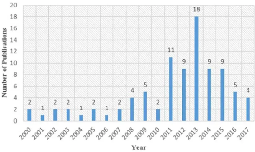
Figure 2-6 Number of VR/AR published articles in journals between 2000 and 2017 ... 14
Figure 2-7 Architecture of an AR application ... 16
Figure 3-1 Overall methodology ... 23
Figure 3-2 Comparing equipment-related features of different tools ... 24
Figure 3-3 DOFs of a boom lift ... 27
Figure 3-4 Loading and dumping stones using built-in physics in Unity game engine ... 30
Figure 3-5 Effect of terrain following on the truck movement ... 30
Figure 3-6 Workspace around a working man in the construction site ... 31
Figure 3-7 Proposed method for generating articulated equipment and its workspace in different tools ... 33
Figure 3-8 Proposed VR-based method for construction safety training ... 35
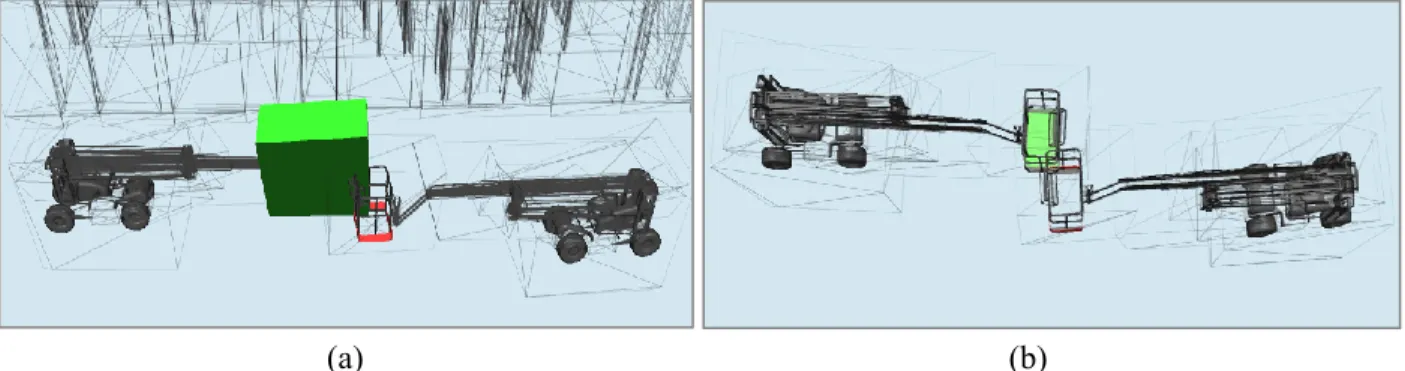
Figure 4-1 (a) Conflicts between equipment and workspace, (b) Clashes between two Equipment ... 45
Figure 4-2 Two frames of an animated crane ... 46
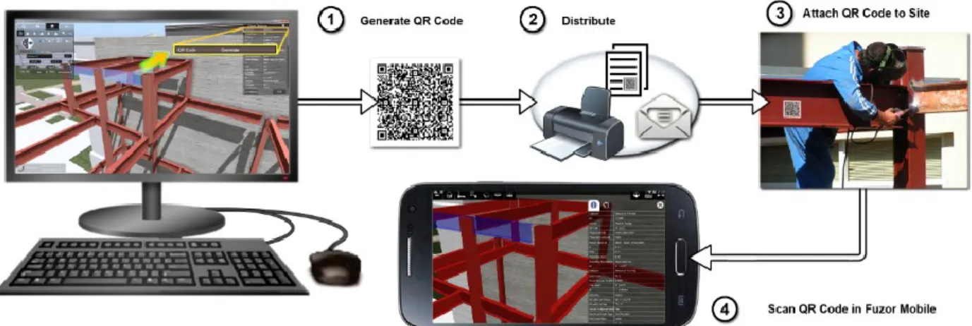
Figure 4-3 Generation and usage of QR codes in a virtual construction site ... 47
x
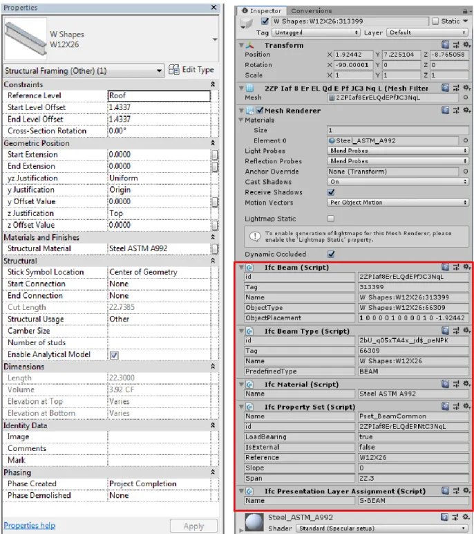
Figure 4-5 Attributes of a component in Revit and Unity ... 49
Figure 4-6 A specific crawler crane in the library of 3D Lift Plan ... 50
Figure 4-7 Flowchart of creating articulated equipment and its workspace ... 53
Figure 4-8 (a) Solid 3D model, (b) Creation of bones and IK Chains, (c) Kinematics model of the boom lift ... 54
Figure 4-9 Create workspace tab in synchro software ... 55
Figure 4-10 Several frames of animated boom lift and its workspace in Lumion ... 55
Figure 4-11 Snapshots of the construction of steel framed church ... 56
Figure 4-12 The names of the structure components ... 57
Figure 4-13 4D Simulation tabs in Fuzor ... 58
Figure 4-14 Resource allocation ... 58
Figure 4-15 Equipment library... 59
Figure 4-16 Micro-tasks of the simulated crane ... 59
Figure 4-17 Flowchart of animating crane movements ... 61
Figure 4-18 The sequential steps of erecting the structure in 4D and assembling time ... 67
Figure 4-19 Allocating structure components ... 69
Figure 4-20 Assembling two struts ... 70
Figure 4-21 Workers’ activities in a narrow space ... 70
Figure 4-22 The sequential steps for modeling the structure in 4D (assembling time) ... 73
Figure 4-23 (a) The error message of conflict detection, (b) Conflicts between two cranes ... 74
Figure 4-24 Hazard identification in VR ... 76
xi
LIST OF TABLES
Table 2-1 Research studies about construction safety training using VR and VR ... 19
Table 3-1 Safety training scenarios... 36
Table 3-2 Protocol for the training ... 38
Table 3-3 Protocol for the testing ... 39
Table 4-1 Comparison between purposed platforms ... 51
Table 4-2 Scheduling in 4D simulation ... 62
Table 4-3 Detailed schedule of equipment movements ... 64
Table 4-4 Scheduling in 4D simulation (Case study 2) ... 71
Table 4-5 Micro-scheduling of the equipment activities (Case study 2) ... 72
xii
LIST OF ABBREVIATIONS
Abbreviation Description 3D 4D AEC AR BIM CAD CAVE DEW DOF FBX GPS HMD IFC IVE LOD MR NBIMS OSHA PPE RFID UWB VDC VR WLAN Three-dimensional Four-dimensionalArchitecture, Engineering, and Construction Augmented Reality
Building Information Modeling Computer-Aided Design
Cave Automatic Virtual Environment Dynamic Equipment Workspaces Degrees of Freedom
Filmbox
Global Positioning System Head-Mounted Display Industry Foundation Classes Immersive Virtual Environment Level of Detail
Mixed Reality
National Building Information Modeling Standards Occupational Safety and Health Agency
Personal Protective Equipment Radio Frequency Identification Ultra Wideband
Virtual Design and Construction Virtual Reality
1
1
CHAPTER 1 INTRODUCTION
1.1 General information
Construction equipment constitutes an important portion of the resources used on construction sites. Every year, many construction workers die at work due to being struck by equipment, caught between objects, and falls. In 2017, 4,674 labor fatalities in the private industry were documented in the United States, within which 971 deaths (or 20.7%) were in construction (OSHA, 2017).
Four-dimensional (4D) Building Information Modeling (BIM) is developed by linking a Three-dimensional (3D) BIM and the corresponding activities in the schedule. In the planning and construction phase, equipment movements and workers’ activities can be simulated and visualized in a 4D model with a high Level of Detail (LOD) to improve the safety, productivity, and constructability of construction projects. This type of high 4D-LOD modeling requires a very detailed schedule, which can capture micro-tasks (e.g. the swing movement of the boom of a crane). Linking the detailed 3D BIM model with the micro-tasks executed by equipment (e.g. cranes) can lead to better simulation of construction activities (Akhavian and Behzadan, 2015).
On the other hand, Virtual Reality (VR) and Augmented Reality (AR) are used in various industries (e.g. medical, game, and construction) for different purposes such as education, entertainment, and facilities management. Safety knowledge is an important factor that promotes safety and health in the construction industry. Some research works have used these technologies for construction safety education with the purpose of enhancing the safety knowledge of the construction workers (Sacks et al., 2013), equipment operators (Wang et al., 2004b), and construction students (Lin et
2
al., 2011; Le et al., 2015). However, the existing research studies have not used 4D VR for construction safety training.
1.2 Problem statement
Some research issues have been identified in accordance with the conducted literature review explained in Chapter 2: They are classified as the followings: (1) Visualization of equipment operations in 4D, (2) Use of 4D VR in construction safety training.
(1) Visualization of equipment operations in 4D
Although many research works discussed the possibility of improving the safety of construction sites using sensors and analyzing the equipment workspaces, these works cannot be linked with available 4D BIM tools, which cannot easily represent equipment movements. On the other hand, 4D BIM tools provide the users with the basic functions for animating and scheduling equipment activities.
(2) Use of 4D VR in construction safety training
The available research works focused on training workers, equipment operators, and students in the 3D virtual environments. However, they need to visualize and experience hazards in a realistic field, in which the construction processes and equipment movements are demonstrated with attention to the schedule. Many accidents and fatalities happen because workers are not familiar with the equipment operations and the risks that may threaten their lives. For example, when the components of a crane (boom and hook) are moving to unload a component, no one should stand or walk in the danger zone.
3
1.3 Research objectives
The objectives of the present research are the followings:
(1) Identifying the requirements for construction equipment modeling and comparing the available commercial and research platforms in terms of visualizing, animating, and simulating equipment movements, and identifying the potential improvements based on the discussed requirements;
(2) Animating and scheduling the construction processes at the micro-level in 4D BIM, such as construction equipment operations along with all resources available on construction sites; and
(3) Enhancing and evaluating the safety knowledge of construction management students in terms of Personal Protective Equipment (PPE) and equipment-related hazards using VR.
1.4 Thesis organization
This thesis will be organized as follows:
Chapter 2 Literature Review: The most related and significant topics, including the development
trends of BIM, applications of 3D and 4D BIM in the construction industry, visualization of equipment activities and equipment workspaces are covered in this chapter.
This chapter also reviews the development of VR technologies as well as their usage in the construction industry. Furthermore, some research works that focus on the use of these technologies in construction safety training are reviewed.
Chapter 3 Proposed Approach: This chapter is divided into three parts. In the first part, the
4
articulated equipment and a safe zone around its components is proposed in the second part. This chapter finishes with a framework, at which 4D VR is used for safety training of construction students. In addition, seven safety training scenarios and protocols related to training and testing are presented in this chapter.
Chapter 4 Case Studies: In this chapter, the available commercial and research platforms are
compared based on the requirements for construction equipment modeling, discussed in the previous chapter. Case studies are provided, at which the equipment activities are animated and scheduled at the micro-level with attention to workers’ activities and the existing details in the construction site. Furthermore, a 4D virtual construction site with some potential hazards is used for safety knowledge training. The research method is validated through a learning experience evaluation and statistical analysis.
Chapter 5 Summary, Conclusions, and Future Work: In this chapter, the present research work is
summarized and its contributions are highlighted. Additionally, the limitations and some recommendations for future work are discussed.
5
2
CHAPTER 2 LITERATURE REVIEW
2.1 Introduction
This chapter reviews the previous research, frameworks, and methods in the areas of BIM, 4D applications, visualization of equipment activities, VR in construction, and construction safety training. Section 2.2 focuses on the development trends of BIM, and applications of 3D and 4D in construction, especially in safety. Some research that visualized the equipment activities in 4D is reviewed in Section 2.3. The available trends in research are analyzed to identify the gaps for modeling and scheduling the construction activities and especially the equipment tasks. This chapter finishes with the explanation of VR and AR technologies and their usages in the construction industry. Some research works that have used these technologies for construction safety training for construction workers, operators, and students are reviewed.
2.2 Development trends of BIM
In the late 1970s and early 1980s, some studies conducted in USA and Europe about parametric modeling that formed the basis of BIM, though it was used practically in the projects from the middle 2000s (Salman Azhar et al., 2015). The National Building Information Modeling Standards (NBIMS) defined BIM as follows: “A BIM is a digital representation of physical and functional characteristics of a facility. As such it serves as a shared knowledge resource for information about a facility forming a reliable basis for decisions during its lifecycle from inception onward (NBIMS, 2016).”
3D tools enable Architecture, Engineering, and Construction (AEC) sector and project managers to visualize the construction projects through realistic images. However, it does not provide the
6
planners with the scheduling and construction progress control. 4D can be used to check the integrity of construction orders and schedules, to evaluate site accessibility, spatio-temporal conflicts, temporary structures, and various construction methods (Hartmann et al., 2008)
At the beginning of the 1990s, an enthusiasm has been formed for 4D applications in construction project management (Heesom and Mahdjoubi, 2004). A center at Stanford University, which is named Integrated Facility Engineering, utilized the idea of 4D-CAD for the first time in 1996 (Wang et al., 2004a).
In spite of the advantages of using CAD, it is faced with the following flows: (1) 3D CAD is a combination of independent 3D views such as plans and elevations. If the user edits and changes one of these views, all other views need to be updated. This process is time- consuming and error-prone. (2) The existing data in CAD drawings are only graphical entities such as arcs and lines. The entities do not carry any information about the physical and functional features of the project resources within its life cycle (Salman Azhar et al., 2015)
2.2.1 3D and 4D applications in construction
Heesom and Mahdjoubi (2004) reviewed the research about 4D models related to the construction industry and identified three different categories based on their specific areas of applications: Product modeling and visualization, process modeling and analysis, and collaboration and communication. Project managers use 4D to dynamically visualize the sequence of construction, resource utilization, workspace logistics, and equipment operations (Wang et al., 2004a).
Hartmann et al. (2008) categorized the application areas of 3D/4D models based on the 26 reviewed case studies into seven parts: photorealistic renderings, virtual design review, analyzing
7
design options/building operations, cost estimating, analyzing construction operations, construction document production, bid package preparation.
Photo realistic renderings allow the project stakeholders and AEC sector to visualize facilities. When the project is simulated and visualized from the view of a human’s perspective through 3D walkthroughs and movie clips, the communication between the stakeholders related to the proposed design will improve (Whyte et al., 2000). Project designers use 3D virtual models to communicate design concepts to the stakeholders and other designers in various sectors. This communication results in detecting and resolving the unexpected conflicts that may happen among the designs of electrical, mechanical, and plumbing sectors (Hartmann et al., 2008).
3D models can be used as input in simulation software for analyzing the design options and building operations. Fischer and Kam (2002) described the application of 3D on predicting the energy consumption and the interior lighting of a building. Furthermore, 3D models can be utilized to estimate the project cost and provide a bill of quantity. A direct link between the model and the cost estimating database can also be established.
4D can be used to analyze construction operations within most phases of the project. However, it is mainly used to plan the construction operations before the beginning of erection of the related part. 3D/4D models can improve and accelerate the development of design and construction documents, and facilitate the provision of the bid package for the contractors and subcontractors since they can visualize the construction sequences (Hartmann et al., 2008).
8
2.2.2 4D applications in construction safety
The control of construction processes in 4D leads to the safety improvement in construction sites through detecting the time-space conflicts (Koo and Fischer, 2000; Akinci and Fischer, 2000; Heesom and Mahdjoubi, 2004; Trebbe et al., 2015; Choi et al., 2014; Hartmann and Dorée, 2015; Shang and Shen, 2016). Some research studies identified time-space conflicts and categorized them based on the problems that they make (Akinci and Fischer, 2000).
4D simulation can be used to analyze safety measures in construction sites (Hammad et al., 2012). Combination of safety rules, 3D models, and schedule information can be used to develop a system that automatically checks safety rules to detect hazards (Zhang et al., 2011). Zhang et al. (2013) developed a safety rule translation algorithm to automatically find safety dangers in the 4D BIM. However, this research is limited to fall protection.
Choi et al. (2014) recommended a 4D BIM-based framework for workspace planning, in which a spatial clash-detection algorithm and problem solutions with attention to movability and functionality of each activity were proposed. In addition, Shang and Shen (2016) developed a spatio-temporal matrix and workspace conflict matrix to detect workspace conflicts on construction sites. Conflict data were analyzed with the proposed frequency index and severity index for 4D site safety assessment.
2.3 Visualization of equipment activities in 4D
Simulated equipment operations can graphically be visualized in 3D (Kamat and Martinez, 2001; Kamat and Martinez, 2005), though the temporal aspects of equipment movements are ignored in 3D visualization. Pradhananga and Teizer (2013) created a user interface (RAPIDS GPS Data
9
Visualizer) that displays temporal positioning data of construction equipment using Global Positioning System (GPS) data. Additionally, Cheng and Teizer (2013) proposed a framework that streams data from location tracking sensors (GPS and UWB) to a VR visualization platform in real-time. The resources sensor data (equipment, workforce, materials), which were linked to the elements of the virtual construction site, were updated by a local real-time data server. Nevertheless, not only the equipment tracking data should be considered, but also equipment tasks need to be visualized.
Kim et al. (2011) presented a case study where a cable-stayed bridge construction was modeled at three different levels of detail in 4D CAD: activity, discrete, and continuous operations. Activity and discrete operations did not show the movements of the equipment components, although the boom movements of a derrick crane were visualized in the continuous operation level in Autodesk Inventor platform. However, this process is time-consuming and constraint conditions should be defined for derrick crane manually. Zhou et al. (2015) presented a 4D case study explored in the oil and gas industry at the operation level and activity level. They established a 4D BIM model with the animated crane in Navisworks and integrate mathematical algorithms with 4D models to simulate the construction activities in detail. For visualizing the crane movements ( e.g. lifting the object by the hook and boom rotation), the parts of the crawler crane were deconstructed and animated separately.
2.3.1 Generation of construction equipment workspace
Capabilities of tools to generate workspaces for construction resources (e.g. building components, equipment, and crew) can reduce hazardous accidents and improve productivity. Some research studies focused on generating workspaces automatically in 4D (Akinci and Fischer, 2000; Akinci
10
et al., 2002a). Akinci et al. (2002b) categorized spaces into three main groups, including macro-level spaces, micro-macro-level spaces, and paths. The spaces for equipment, crew, protected, and hazard areas were included in micro-level spaces. Akinci and Fischer (2000) suggested a prototype system, 4D WorkPlanner, which automatically generates micro-level spaces.
Additionally, there are some research works that concentrated on equipment workspace generation (Tantisevi and Akinci, 2007; Vahdatikhaki and Hammad, 2015). Zhang et al. (2015) utilized remote sensing (GPS data) and workspace modeling technologies for automated visualization of workspaces (worker, equipment, building components, etc.) in BIM. Shang and Shen (2016) developed a method that visualized and modeled 3D workspaces of equipment and workers, categorized into static and dynamic workspaces. Vahdatikhaki and Hammad (2015) proposed an approach for producing Dynamic Equipment Workspaces (DEW) for increasing earthwork safety, at which both the present state and position of the equipment and the speed features of each movement were considered (Figure 2-1).
Figure 2-1 2D DEW representation of an excavator in swinging condition (Vahdatikhaki and Hammad, 2015)
11
2.4 Virtual Reality (VR) and Augmented Reality (AR) 2.4.1 Definition and scope
VR is a kind of technology enabling users to immerse in and interact with a 3D/computer-generated virtual environment, a simulation of either the real world or imaginary world. VR technologies can be used for different purposes such as education, building design, construction, check of safety, and entertainment (Mazuryk and Gervautz, 1996).
VR was taken into consideration in the 1950s, though it drew public’s attention in the late 1980s and 1990s. Jaron Lanier used the term ‘virtual reality’ for the first time in 1987 (Mandal, 2013). Ivan Sutherland suggested the first concept of making an artificial world in 1965, in which force feedback, sound, and interactive graphics were included (Tommaso and Paolis, 1994). As Figure 2-2 shows, he also built the first Head Mounted Display (HMD) with head tracking in 1968, at which the views became updated based on the positions and orientation of the consumer’s head (Sutherland, 1968). Figure 2-3 shows the different types of common HMD.
12
Figure 2-3 Oculus Rift (2019), HTC Vive (2019), Sony PlayStation VR (2019), Oculus Go (2019), and Samsung Gear VR (2019) (from left to right)
In 1992, Cave Automatic Virtual Environment (CAVE) as a VR environment and a room-sized immersive visualization system was utilized besides using HMD (Figure 2-4). It overcomes the limitations of HMD by: (1) providing a wider and larger field of view; (2) visualizing high quality and resolution images; (3) wearing light pieces of equipment (e.g. LCD shutter glasses); and (4) Immersing simultaneously multi users in the same VR environment (Mandal, 2013).
Figure 2-4 The usage of CAVE in VR (the picture is retrieved from (ESI Group, 2017))
VR technologies are faced with some challenges that should be improved or solved within the next years: (1) managing large-scale VR projects with a large amount of data; (2) improving the current tracking systems; and (3) reducing the required time for generating virtual spaces.
On the other hand, AR is a modern technology that superimposes computer-generated information onto the real world (Chi et al., 2013). AR technologies are used in different domains such as education, design and construction, maintenance and repair, medical visualization, advertising, and
13
entertainment (Carmigniani et al., 2011). It is expected that the usage of AR applications will be increased in the near future and widely utilized in the industrial field.
Caudell and Mizell (1992) from Boeing coined the term “Augmented Reality” and talked about the advantages of AR as supposed to VR. Furthermore, They prototyped a heads-up display headset (HUDset) system with position sensing technologies, in which the head was tracked in six degrees of freedom (Figure 2-5). In 2000, Bruce Thomas developed the first mobile AR game, ARQuake, in which users walk around in the real environment and play the Quake game through their mobile phones (Thomas et al., 2000).
Figure 2-5 The components of a HUDset (Caudell and Mizell, 1992)
2.4.2 Research trends of VR and AR in construction
Li (2010) introduced some applications of VR in construction: (1) visualizing construction space; (2) urban planning; (3) web-based information system for construction; (4) a Distributed Virtual Reality (DVR) tool for construction and education; and (5) visualizations of building structural behavior. Figure 2-6 shows the number of VR/AR-CS articles related to construction safety that were published in selected journals from 2000 to 2017 (Li et al., 2018).
14
Figure 2-6 Number of VR/AR published articles in journals (e.g. AIC, JCCE, ITCon, etc.) between 2000 and 2017 (Li et al., 2018)
2.4.2.1 VR/AR in construction visualization
Since computers enable the creation and visualization of sophisticated graphics, VR technology is used in construction planning (Dunston et al., 2005), structural analysis and architectural design (Li, 2010) to visualize and interact with difficult concepts. The design model can be visualized in the 3D VR environment, and the sequencing of construction activities can be visualized in 4D VR (Dunston et al., 2005).
Behzadan and Kamat (2007) proposed a method to graphically simulate the scheduled construction activities for the erection of a steel structure in outdoor 4D AR. Golparvar-Fard et al. (2009) utilized a location-based image processing technique to visualize and compare differences between as-planned and as-built performances in the 4D AR, using traffic light metaphor.
In construction sites, accurate and long-term trackers and sensors are required to track location and movement of equipment, workers, and materials (Dunston et al., 2005). Various tracking technologies can be used such as Radio Frequency Identification (RFID), Ultra Wideband (UWB), and GPS (Vahdatikhaki et al., 2015). Behzadan et al. (2008) used location tracking techniques
15
such as Wireless Local Area Network (WLAN) and GPS to visualize the construction operations in AR.
2.4.2.2 VR/AR and BIM
The AEC industries have focused on the usage of digital information so that advanced visualization platforms and technologies are required to efficiently use this information (Chi et al., 2013). Mixed Reality (MR) technologies can enhance the information accessibility for decision makers in different parts of the project such as design review, planning, monitoring, and inspection. In particular, AR is useful to the construction industry because in the AEC sector, workers and operators can interact with digital information in real-time while performing their work tasks (Dunston et al., 2005).
The systems integrating BIM with AR enable the display of an immersive model into the real world and the visualization of the as-planned data onto the as-planned environment (Wang et al., 2014). AR enables the visualization and representation of building information through virtual models (Gu et al., 2010). Wang et al. (2013) proposed a conceptual framework for integrating BIM with AR, which enables the visualization of the physical context of construction tasks in real-time. It addressed the gap between integrating BIM and real-time communication on-site.
Gu et al. (2010) suggested an AR interface for a BIM server, in which on-site construction data is coordinated and integrated with the BIM model for the updating and verification of the construction progress. This leads to the improvement of the collaboration and information exchange on the construction site.
16
The concept of BIM+AR can be used for improving the following aspects related to construction site activities: interdependency, linking digital to physical, synchronization of mental models for communication, project control and monitoring (as built versus as planned), procurement, visualization from design to production, and site plan and storage (Wang and Love, 2012).
However, AR technologies are faced with some limitations when a huge amount of information is required. Therefore, at the construction site, at which a huge amount of data should be processed, databases, convenient methods, and additional integrated technologies with AR should be utilized. Figure 2-7 shows four technologies that influence directly on the development of AR applications including localization, cloud computing environment, portable and mobile devices, and natural user interface (Chi et al., 2013).
Figure 2-7 Architecture of an AR application (Chi et al., 2013)
2.4.3 Construction safety training using VR/AR
One of the areas that VR/AR technologies are used is training (Lin et al., 2013; Le et al., 2015). The inherent dangers of construction sites cause difficulties in onsite training so that it is needed to instruct trainees on how to expose and overcome dangers in a safe way. Construction workers
17
and equipment operators can virtually be trained to be able to identify and analyze the magnitude of potential construction risks (Lucas et al., 2008; Sacks et al., 2013).
Different training methods are used in the construction industry such as lectures, pictures, demonstrations, and videos. These traditional methods, which are common in construction, do not allow trainees to engage deeply in the project. Based on the findings of a meta-analysis study of research works between 1971 to 2003 (Burke et al., 2006), which analyzed and compared the effectiveness of the safety and health training methods, high engaging training approaches (e.g. behavioral modeling and hands-on training) were approximately three times as effective as low engaging training in terms of knowledge and skill development.
Immersive Virtual Environment (IVE), which is considered as a high engagement training, engages the senses of trainees. Sacks et al. (2013) compared the role of conventional methods and VR technology in enhancing the safety knowledge of construction workers by using IVE power-wall (cave automatic virtual environment). According to their findings, the following items can be considered as the benefits of using VR in construction safety training: (1) trainees can interact realistically with hazards available on construction sites; (2) safety training with VR catches trainees’ attention more than conventional training methods; (3) VR gives users more opportunities to control the construction environment.
2.4.3.1 Safety training for students, workers and equipment operators
Students should be taught to identify job hazards for having a safe working environment in the real construction site. Lin et al. (2011) proposed a 3D video game to promote the ability of students for identifying construction hazards and safety violations.
18
Le et al. (2015) proposed a framework for utilizing mobile-based VR and AR for construction safety education. Based on their method, firstly safety guidelines and regulations were introduced to construction students based on accident samples by utilizing VR/AR technology. Secondly, students were asked to inspect a virtual construction site to identify the hazards. Finally, trainees’ safety knowledge was assessed through the use of VR serious games and AR multiple choice exams. Since the development of hazard scenarios in virtual and augmented contents are time-consuming, BIM model of a construction project can be utilized.
VR-based simulators (Vahdatikhaki et al., 2017) and AR-based system (Wang et al., 2004b) can be used in equipment training programs. The safety on construction sites would improve when heavy equipment operators are properly trained for risky and complex scenarios. It should be mentioned that VR equipment training simulators such as Vortex simulators (CM Labs Simulations, 2018) are developed contingent on hypothetical scenarios, while different factors affect the performance of the equipment operators on actual construction sites such as the location of the site and the performance of other pieces of equipment and workers. The uncertainties resulting from human decisions on real construction sites can be simulated within VR-based training simulators (Vahdatikhaki et al., 2017).
Wang and Dunston (2007) designed an AR-based system with some scenarios for the training of heavy construction equipment operators. This system enabled operator trainees to practice operations on a predesigned construction site while sitting in a piece of heavy equipment. Lucas et al. (2008) suggested the use of VR for conveyor belt training. Based on their proposed safety training structure, mine employees can interactively experience working with conveyor belt systems. Additionally, crane movements (e.g. lifting up loads) can be controlled in a virtual crane
19
training system using control commands that are extracted from facial gestures of users (Rezazadeh et al., 2011). The summary of the previous studies related to the use of VR and AR in construction safety training is given in Table 2-1.
Table 2-1 Research studies about construction safety training using VR and VR Author (s) and
year of publication
Specified group for training Technology
Domain (s) of safety training Equipment
operators Students Workers VR AR Vahdatikhaki
et al. (2017) Operating the equipment safely alongside other equipment movements Le et al. (2015) Falling Sacks et al. (2013)
General site safety, stone cladding work & cast-in-situ concrete work Lin et al. (2011) Varied Lucas et al. (2008)
Conveyor belt safety Wang and
Dunston
(2007)
Earth-moving, material-handling, and pipe-laying operation
Wang et al.
(2004)
Loading operation
2.4.3.1 Mobile-based VR and AR
VR, AR, and mobile computing can be used for construction safety training. Mobile computing such as mobile devices and laptops provide users with computing service anytime and anywhere (Anumba and Wang, 2012). It allows construction field managers and facilities managers to check the project on the site and communicate with AEC stakeholders. The usage of mobile computing
20
in training would provide students with fast information access, easy communication and collaboration, and situated learning (Gikas and Grant, 2013).
The use of AR technologies is increasing every day since cell phones, pads, and other mobile devices are becoming smaller, lighter, cheaper, and more user-friendly and powerful (Chi et al., 2013). MR technology-based systems can provide the AEC sectors with handheld aids for workers in dangerous situation supplying information about 3D models in near at the construction site (Dunston et al., 2005). Moreover, new forms of remote collaboration and shared experiences can be achieved by MR technologies (Keneman and Waller, 2016).
2.5 Summary and conclusions
This chapter reviewed the concepts and main technologies that are utilized in the current research such as 4D applications, safety, 4D BIM, VR systems, and construction safety training. The literature showed that 4D has been widely used in construction. Specifically, 4D BIM is broadly used for visualizing, animating, and scheduling the construction activities. However, the review of previous research works has shown that construction equipment tasks are not animated and scheduled at the micro-level. Modeling and scheduling the construction equipment activities and its workspaces increase the safety and productivity in construction sites.
Additionally, the usage of MR technologies has increased in recent years in various areas such as training and education. Some researchers have benefited from VR and AR-based technologies in construction safety training for workers, operators, and students. Nevertheless, many construction accidents arise from insufficient knowledge of student about equipment operations. There is a
21
research gap on equipment-oriented VR/AR training in order to enhance students’ capabilities for identifying on-site hazards.
22
3
CHAPTER 3 PROPOSED METHODOLOGY
3.1 Introduction
As explained in Chapter 2, many research works have simulated equipment activities by using different methods and applications. More research can be carried out to simulate and schedule equipment operations at the micro-level in 4D BIM. In addition, many researchers used 3D VR technologies to train construction workers; however, training in the 4D virtual environment can provide new opportunities.
This chapter is divided into three parts. In the first part, requirements for modeling construction equipment are represented in seven main categories. To visualize the construction progress from the beginning to the end with all related details, the conditions needed for simulating the equipment operations should be taken into account.
In the second part, the author moves one step beyond introducing requirements for equipment modeling and proposes an approach for modeling equipment tasks in different software tools with regard to the discussed requirements. Different types of construction equipment can be made articulated through the proposed method. In addition, a method for generating dynamic workspace for equipment is designed, which can help in developing more detailed simulation, and consequently, can result in improving safety on construction sites.
Based on the comparison, Fuzor VDC was utilized to create the 4D simulation and to use it for application in VR safety training (Figure 3-1). In the third part, a VR-based framework, which focuses on safety knowledge training and testing, is proposed to improve students’ capability for identifying on-site hazards. Through the proposed framework, learners can navigate in a BIM
23
model in the virtual environment and recognize PPE–related safety issues in the 3D/4D VR. Additionally, the existing hazards during the construction activities and equipment operations can be detected in the 4D VR.
Comparing Equipment-related Features of Different Tools
and Selecting Appropriate Software
Developing the 4D Construction Simulation
Using 4D Simulation in VR Safety Training Figure 3-1 Overall methodology
3.2 Proposed method for comparing equipment-related features of different tools
To compare the available commercial and research platforms in terms of animating and simulating construction equipment, the steps shown in Figure 3-2 can be followed. The requirements for equipment modeling are identified and the specific software tools to be compared are selected. An example is developed in each tool to evaluate its capabilities for making articulated equipment. Then, a comparison based on the mentioned requirements is carried out to summarize the strengths and limitations of each tool.
24
Identifying the Requirements for Construction Equipment Modeling
Developing the Same Example in Different Platforms
Comparing Equipment-related Features of Tools based on the Identified Requirements Selecting Different Tools Including BIM and
non-BIM Platforms 3D Animation Software 4D BIM Software Game Engine Other Tools Start End
Figure 3-2 Comparing equipment-related features of different tools
3.2.1 Requirements for construction equipment modeling
To prevent accidents and mismatches in the construction phase, the whole construction activities and equipment tasks should be scheduled and visualized in the planning phase. Each of the tools has some strengths and limitations for animating and visualizing equipment-related features, which will be discussed in the next chapter. To appropriately visualize the construction progress and
25
improve safety and constructability in construction sites, the tools should satisfy some requirements for animating and simulating construction equipment activities.
3.2.1.1 BIM compatibility
BIM has the capability to schedule, simulate, and visualize equipment tasks in detail. Compatibility between construction equipment modeling and BIM results in better visualization of the progress of the construction activities by simulating equipment movements and the changes in workspaces at the micro-schedule level.
IFC (Industry Foundation Classes) is an open and neutral data format for openBIM, which is developed by buildingSMART (2018) to support the seamless information exchange among AEC participants. Several BIM platforms provide visualization and schedule of equipment activities. However, there are limitations to exchange equipment-oriented information in BIM since the equipment is not considered in the current version of IFC, except as an abstract type of IfcResource (2019).
3.2.1.2 Equipment library
BIM tools usually have a library of common objects, ranging from materials and furniture to equipment. However, most of the tools do not have a library of construction equipment. The vehicle objects, which are available in most of these libraries, lack the inverse kinematics feature.
Additionally, the dissimilarity between simulated equipment objects and the real pieces of equipment can cause errors and misunderstanding. Ideally, the equipment library should include not only the set of equipment commonly used in construction projects (e.g. excavators, cranes,
26
compactors, etc.) but also the specific types of the equipment based on different brands, sizes, etc. Some crane simulation tools (e.g. 3D Lift Plan, 2019) have a detailed library of cranes including the crane models and the load charts.
3.2.1.3 Ability to model multiple Degrees of Freedom (DOFs)
The DOFs of articulated equipment with moving parts define the pose of the equipment. In general, there are six degrees of freedom for solid objects including three translations and three rotations, which show the movement freedom of a rigid body in three-dimensional space. As a result, to properly control the equipment movements, its DOFs should be easily controllable in the simulation tool. Platform users should be able to select a specific value within the range of each DOF of the equipment.
As shown in Figure 3-3, a typical boom lift (cherry picker) could be controlled through eight DOFs: W1, W2, W3, W4, W5 (Vb), W6, W7, and W8 (V). It consists of two translation transformations; the whole boom lift moves toward the left and right direction through V vector while Vb controls extensions of an arm. Also, the boom lift is controlled by four pitch rotations (W2, W3, W4, and W6) and two yaw rotations (W1 and W7). Two or more DOFs might be combined at any point in time. However, the movements and rotations of some parts are constrained. For example, the boom lift’s bucket should be kept horizontal. Appendix A represents more pieces of equipment with their DOFs.
27
Figure 3-3 DOFs of a boom lift (Model of the boom lift is retrieved from (GrabCAD, 2019))
3.2.1.4 Ability to model at high 4D-LOD
With the purpose of full analysis of construction equipment activities, 4D-LOD for equipment simulation should be able to link micro-tasks of the movement of the equipment components with the detailed schedule of these tasks (e.g. the swinging of the boom of a crane). Equipment tasks should be broken to high LOD to enhance the safety, productivity, and constructability in construction sites. Project managers can create an efficient plan if they model equipment on construction sites based on accurate activity time. If an error is observed prior to or during the construction phase, they can reschedule tasks through changes in start time, end time, duration, and sequence of tasks.
Six LODs are defined for 3D BIM models including LOD 100, LOD 200, LOD 300, LOD 350, LOD 400, LOD 500 (AIA, 2017).On the other side, LODs for schedules are classified into five levels: level 1 to level 5 (Stephenson, 2007). However, there is no specific definition for 4D-LOD.
28
Guevremont and Hammad (2019) proposed new guidelines for defining 4D-LODs at different phases of a project by considering the needs of different stakeholders.
3.2.1.5 Path and motion planning
Path and motion planning of the construction equipment is an important part of 4D construction simulation. This planning has two parts: planning the relocation path of equipment (e.g. relocation of an excavator between two locations on the site), and planning of the movements of the parts of equipment (e.g. the boom swing, trolley and hook movements of a tower crane). Although the former planning may be available in some simulation tools, planning of the movements of equipment parts is still done manually in these tools, which is time-consuming. Also, it is important to be able to simultaneously plan the movements of several parts of the equipment and to support the motion planning of complex repetitive tasks (e.g. for cranes and excavators).
3.2.1.6 Collision avoidance
Congested site conditions often result in poor safety and productivity performance (Zhang et al., 2015). Congestion causes objects to move slowly, which results in an increase in cycle time and a decrease in productivity. On the other hand, it is important to be able to detect conflicts between different resources available in the construction sites. The probability of accidents between pieces of equipment, workers and equipment, and equipment and building components increases when the pieces of equipment do not have enough spaces to do their tasks. If equipment conflicts can be identified in advance, productivity and safety would be enhanced through rescheduling. The same approach used for time-dependent clash detection in the 4D simulation can be utilized for equipment conflict detection. The conflict detection and collision avoidance can be based on the
29
actual 3D model of the equipment or based on its dynamic workspace, which can be generated automatically (Vahdatikhaki and Hammad, 2015).
3.2.1.7 Other requirements Setting speed of movements
Different components of equipment (e.g. the boom and hook of a crawler crane) move at variable speeds based on the type of activity. It is important to set a specific speed for each equipment movement because this affects the cycle time and productivity. From a safety point of view, an accident may happen due to task interference when the speed of movements are ignored during modeling. This increases the probability of conflicts due to differences between planned and actual activity times.
Time scale
Each piece of equipment performs a set of activities during the construction project that may take minutes or even seconds. For modeling and visualizing equipment activities at high LOD, their tasks should be scheduled at the micro-level in 4D.
Physics, terrain following, and ability to simulate weather conditions
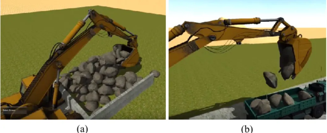
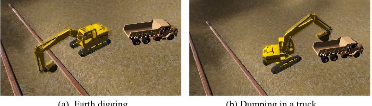
The physical behavior of objects, such as wind effects, gravity, and terrain following have direct effects on equipment performance. The users can use computer-simulated construction sites and the physical behavior of objects can be controlled with built-in physics engines. Figure 3-4 (a) and (b) show an excavator loading stones from the ground and dumping them in a truck considering gravity physics in Unity game engine.
30
(b) (a)
Figure 3-4 Loading and dumping stones using built-in physics in Unity game engine (AndersOrum, 2015)
In addition, it is important to consider terrain following in the modeling of equipment activities since it affects the equipment performance. Terrain following makes equipment move on the terrain based on the elevation and slope of the ground. Figure 3-5 shows that the trucks’ movement on the terrain is influenced by the soil unevenness. Furthermore, weather conditions impact the equipment movement and its performance. For example, when the weather is snowy or rainy, the operators move the equipment with reduced speed, which affects equipment efficiency.
31
Dynamic work spaces
Workspace is designed to promote safety (Mital and Karwowski, 1991). Workers, building components, materials, and construction equipment occupy static and variable spaces at different stages of a project. Since different parts of the equipment move and rotate, dynamic workspaces for each part should be automatically generated leading to safety improvement. Moreover, workers on foot and who are working on the equipment should also be able to work safely. Figure 3-6 shows the work space around a worker working on a joint of a steel structure.
Figure 3-6 Workspace around a working man in the construction site
3.3 Proposed method for generating articulated equipment
3D animation software focuses on producing 3D models and animations used commonly in the game industry. These platforms can be used to animate the movements of a piece of equipment. On the other hand, BIM platforms have progressed in recent years in terms of visualizing equipment operations and generating workspaces. In addition, game engines are able to simulate equipment activities, although special scripts should be written and applied.
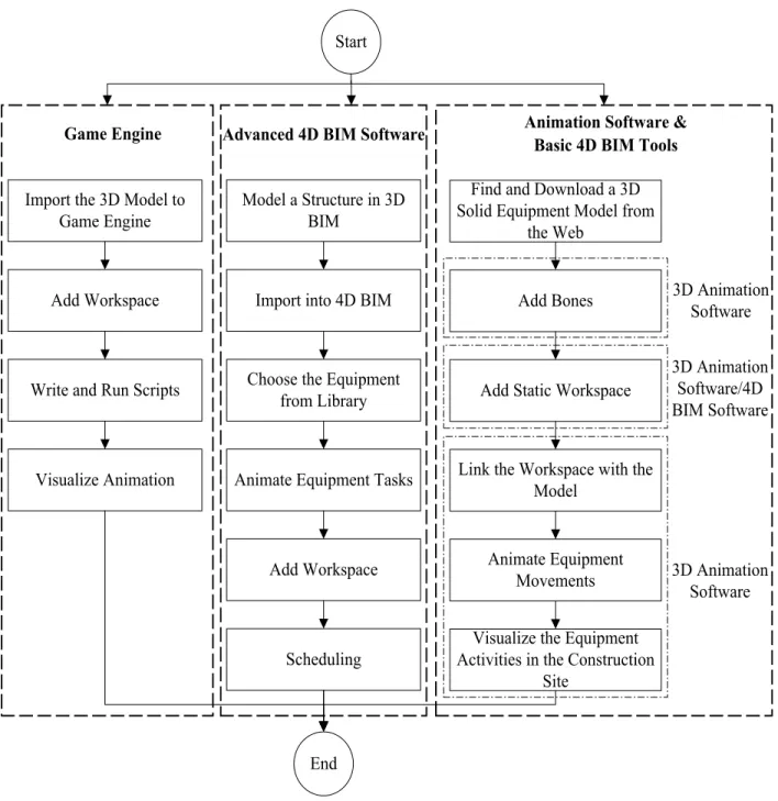
Figure 3-7 proposed the process for animating equipment activities along with their workspace in three different categories of platforms: (1) animation software and basic 4D BIM tools; (2)
32
advanced 4D BIM software; and (3) game engine. To model equipment activities, several tools may be required to combine with each other. Based on the first category, after importing a 3D solid equipment model and adding bones in 3D animation software, static workspace that is created in either 3D animation or 4D BIM software is added to the model. Then, equipment activities are animated and visualized in the construction site. The detailed process is explained in Section 4.3. On the other hand, advanced BIM software can be utilized to animate and schedule equipment activities at micro-level. In the first step, a structure is modeled in a 3D BIM software and imported into the 4D BIM platform. Subsequently, pieces of equipment are selected from the software library before animating their tasks and adding workspace. Their tasks are scheduled by the AEC sector in the planning phase. Two cases in Sections 4.4 and 4.5 are presented based on the mentioned steps. In the third category, after importing 3D model of equipment and adding workspace, related scripts are written to visualize the equipment movements. After these processes, equipment-related characteristics of tools are compared and their positive and negative points are determined.
33
Find and Download a 3D Solid Equipment Model from
the Web Add Bones
Add Static Workspace
Link the Workspace with the Model
Animate Equipment Movements Start
End
Visualize the Equipment Activities in the Construction
Site 3D Animation Software 3D Animation Software/4D BIM Software 3D Animation Software Model a Structure in 3D BIM
Animate Equipment Tasks Import into 4D BIM
Scheduling Import the 3D Model to
Game Engine
Choose the Equipment from Library Write and Run Scripts
Add Workspace Add Workspace
Visualize Animation
Game Engine Advanced 4D BIM Software Animation Software & Basic 4D BIM Tools
Figure 3-7 Proposed method for generating articulated equipment and its workspace in different tools
34
3.4 A framework for using 4D VR for safety knowledge training
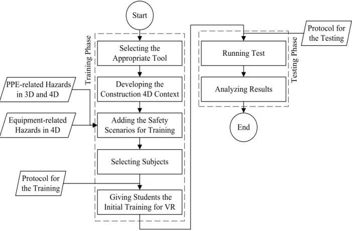
This study aims to provide construction management students with a realistic construction site to improve their safety knowledge. To achieve the study purpose, a VR-based approach is proposed for construction safety training consisting of two phases: (1) Training phase, (2) Testing phase.
Based on the requirements explained in 3.2.1, an appropriate tool is selected to visualize construction activities and equipment operations, as shown in Figure 3-8. In the next step, a construction site along with all details is developed in 4D before adding the safety scenarios for training. Some on-site construction hazards are applied to the model including PPE- and equipment-related hazards. Equipment-related hazards can be better visualized in 4D. However, PPE-related hazards can be observed in both 3D and 4D. In addition, the activities of workers are scheduled based their working hours and can be visualized in VR mode. Then, construction students are selected and provided with the initial safety training for VR in accordance with the prepared training protocol.
Subsequently, students’ safety knowledge is evaluated by running a test based on the testing protocol. They should view the construction activities in the virtual environment to find the hazards. Participators are informed of their performance.
35 Selecting the Appropriate Tool
Developing the Construction 4D Context
Adding the Safety Scenarios for Training
Giving Students the Initial Training for VR
Start End PPE-related Hazards in 3D and 4D Equipment-related Hazards in 4D Running Test Analyzing Results T ra in in g P ha se T es ti ng P ha se Selecting Subjects Protocol for the Training Protocol for the Testing
Figure 3-8 Proposed VR-based method for construction safety training
3.4.1 Safety scenarios for training
Some safety training scenarios are selected based on the hazards that threaten construction workers’ lives. Safety knowledge of students can be improved by training about common on-site hazards and the appropriate related remedies. Additionally, immersing in the high-risk construction project with 4D VR and visualizing the equipment operations helps them in detecting dangers and taking preventative measures. From this point of view, seven virtual safety training scenarios are developed. The types of hazards, descriptions, and required VR environment are explained in Table 3-1.
36
Table 3-1 Safety training scenarios
No. Hazard Description Virtual
environment
Example 1 Walking worker
under crane while its components move
The worker walks on the site without attention to the cranes’ operation. The component may fall from the hook of the crane.
4D
2 Lack of safe
distance between the crane component and the worker on the boom lift
The worker is waiting to release the steel component from the crane. The hook of the crane or the component may hit the worker.
4D
3 Lack of timing and proper coordination between crane operators
Two cranes are operated to erect a steel structure in a limited time and congested site. Due to a lack of proper timing, they can hit each other.
4D
4 Workers without a hard hat
A component falls from an elevated height while the worker works at the site without wearing the hard hat. It can hit his/her head.
3D/4D
5 Workers without a safety harness
The worker assembles a steel component at height, not wearing the safety harness. He/she may fall from the structure due to loss of balance.
37
Table 3-1 Safety training scenarios (continued) 6 Workers without
high visibility clothing (reflective clothing)
The operator of heavy equipment does not see the workers clearly due to the difficult visibility condition.
3D/4D
7 Workers who do not wear gloves
The worker welds the steel component without wearing gloves. It can cause burns, cuts, and scratches.
3D/4D
3.4.2 Safety knowledge training
Some construction management students are selected for the training phase. The purpose of this phase is transferring the safety knowledge to students based on construction hazards. Table 3-2 shows the protocol designed for the safety training of students. Students are trained through two different methods, conventional and VR training. At first, the Occupational Safety and Health Agency (OSHA) guidelines specified in certain domains are introduced. Students become familiar with some accident cases by photos and videos. Learners are supposed to develop their safety knowledge based on the safety regulations and hazard samples.
In the next step, the usage of Oculus Rift as a VR device is explained to students. Users navigate in the virtual site and see the construction processes in the 4D VR. A risky construction project should be utilized as a sample to show students the probable on-site hazards. While they are navigating in the virtual site, the instructor explains the safety risks and appropriate preventative measures for each hazard. Through this experiential approach, students can improve their safety knowledge about safety issues prior to entering the construction site.
38
Table 3-2 Protocol for the training
No. Tasks Technology
support Purpose
Tutor Students
1
Explanation of safety standards and guidelines (OSHA) Receiving Conventional training (lectures) To make students aware of safety rules 2 Introduction of hazard
samples Receiving
Conventional training (photos and videos)
To learn about the importance of recognizing hazards 3 Explanation of the usage of Oculus Rift Receiving Conventional training
To familiarize students with the device
4 Idle Experience of the virtual
environment VR To make students familiar with VR mode 5 Introduction and explanation of hazard scenarios and preventative measures
Navigation through the virtual construction site in 3D and 4D
VR
To enhance the safety knowledge of students
3.4.3 Safety knowledge testing
After the training stage, the safety knowledge of learners should be tested. This process ensures that the students acquire sufficient safety knowledge to be able to detect safety issues of the construction site. The protocol provided for the testing of students’ knowledge is provided in Table 3-3. The Testing phase is carried out by utilizing a 4D VDC platform. Students are provided with the VR technology (Oculus Rift) to immerse in and interact with the construction project. They should navigate in the 3D/4D virtual site for observing issues related to PPE and equipment. They identify hazards by marking around them and suggest measures. By using this approach, the capabilities of students for detecting hazards and their safety-related knowledge are measured.
39
Table 3-3 Protocol for the testing
No. Tasks Purpose
Tutor Students
1 Providing a VR device (Oculus Rift) for students
Idle To begin the test
2 Idle Navigating in the virtual
construction site in 3D
To observe the virtual site and find PPE-related hazards
3 Idle Playing 4D animation
and walk around the site
To look around the environment to discover PPE- and equipment-related hazards
4 Evaluating the performance of student
Identifying the hazards and suggesting
preventative measures
To test the capabilities of students to identify hazards
5 Giving a score to
performance based on the detected hazards
Idle To measure the safety knowledge of students
3.4.4 Learning experience evaluation
After training students about the safety hazards using AR and testing their hazard recognition, they are invited to answer some prepared questions about their learning experience. The following questions have formed the questionnaire: (1) The hazards were represented realistically; (2) The training improved your safety knowledge; (3) You remember what you have experienced clearly; (4) You are interested in experiencing similar training sometimes in the future; (5) You suggest others (your friends) to have similar training; and (6) Visualizing the equipment operations in specific training method has impact on improving your safety knowledge.
These questions are asked in four different areas: (1) Visualization, to assess students’ point of view regarding the reality of demonstrations; (2) Safety recognition, which focused on how well students recognize the hazard on the virtual construction sites; (3) Memory response, which