The Effect of Mobility, Security and
Shadowing on Latest Wireless LAN
Standard (IEEE802.11ac)
By
Abdulbasit Almatrook
A thesis submitted in partial fulfilment of the requirements for the
degree of Master of Computing
ABSTRACT
This thesis focuses on the evaluation of IEEE 802.11ac WLAN performance using TCP and UDP for both versions of the Internet Protocol (IPv4, IPv6) in three scenarios, namely, the effect of implementing WPA2 security encryption, the impact of shadowing in laboratory environment, and human movement effects in indoor environmental conditions. This thesis will also provide knowledge about the behaviour of commonly used protocols on a new wireless standard (802.11ac) in real network environments. The performance metrics of wireless network test-beds such as throughput, round trip time, and CPU utilisation are gathered and analysed. The findings of this study concludes that the shadowing environment has a severe impact of 802.11ac WLAN performance. Applying WPA2 security also reduces the performance metrics measurement. The presence of human movement has an insignificant impact of the 802.11ac WLAN performance. IPv4 outperforms IPv6 on different levels, depending on the network environment. TCP provides lower performance than UDP.
This thesis will be beneficial to academic researchers and to businesses wanting to get the best performance out of IEEE 802.11ac standard.
ACKNOWLEDGEMENTS
I would like to thank my family for believing in me to go further studies and their encouragement. I would like to express my heartfelt thanks for my beloved mom who never stop praying for me to get a highest levels of my life.
I would like to express my gratitude to my supervisor Dr. Samad Kolahi, for giving me the opportunity to work with you, your valuable pieces of advice, and for your guidance and patience.
TABLE OF CONTENTS
ABSTRACT ... i
ACKNOWLEDGEMENTS ... ii
TABLE OF CONTENTS ... iii
LIST OF FIGURES ... vi LIST OF TABLS... ix LIST OF ABBREVIATIONS ... x CHAPTER 1 ... 1 INTRODUCTION ... 1 1.1 Thesis Objectives ... 2 1.2 Related Work ... 3 1.3 Thesis Contributions ... 7
1.4 Structure of the Thesis ... 8
1.5 Chapter Summary ... 9
CHAPTER 2 ... 10
BACKGROUND TECHNOLOGIES ... 10
2.1 An Overview of IEEE 802.11 ... 10
2.2 IEEE 802.11 Architecture ... 12
2.3 Internet Model (TCP/IP protocol) ... 13
2.4 The IEEE 802.11 Standard ... 19
2.5 Wireless Security Protocols ... 19
2.6 Wireless Radio Propagation Characteristics ... 21
2.7 Chapter Summary ... 24
CHAPTER 3 ... 25
IEEE 802.11ac WLAN ... 25
3.1 An Overview of IEEE 802.11ac ... 25
3.2 The Core Technology of 802.11ac ... 26
3.3 Chapter Summary ... 32
CHAPTER 4 ... 33
METHODOLOGY ... 33
4.1 Method of Study ... 33
4.3 Data Collection Process ... 36 4.4 Chapter Summary ... 37 CHAPTER 5 ... 38 EXPERIMENTAL DESIGN ... 38 5.1 Test-bed ... 38 5.2 Experimental Scenarios ... 43 5.3 Chapter Summary ... 48 CHAPTER 6 ... 49
IMPACT OF WPA2 SECURITY ON 802.11ac WLAN PERFORMANCE ... 49
6.1 Throughput Analysis ... 49
6.2 Round Trip Time (RTT) Analysis ... 54
6.3 CPU Utilisation Analysis ... 57
6.4 Comparison Summary of Throughput, RTT, and CPU Usage ... 60
6.5 Chapter Summary ... 62
CHAPTER 7 ... 63
EFFECT OF HUMAN MOVEMENT ON 802.11ac WLAN ... 63
7.1 Throughput Analysis ... 63
7.2 Round Trip Time (RTT) Analysis ... 67
7.3 CPU Utilisation Analysis ... 70
7.4 Comparison Summary of Throughput, RTT, and CPU Usage ... 73
7.5 Chapter Summary ... 74
CHAPTER 8 ... 76
EFFECT OF SHADOWING ON 802.11ac WLAN IN LABORATORY ENVIRONMENT ... 76
8.1 Throughput Analysis ... 76
8.2 Round Trip Time (RTT) Analysis ... 81
8.3 CPU Utilisation Analysis ... 85
8.4 Comparison of throughput, RTT, and CPU utilisation... 89
8.5 Chapter Summary ... 92
CHAPTER 9 ... 93
SUMMARY, CONCLUSIONS, AND FUTURE WORKS ... 93
9.1 Open System vs. WPA2 Security Encryption ... 93
9.2 No Human Shadowing vs. Human Movement ... 94
9.3 The Effect of Shadowing in Laboratory Environment (lab 2005, lab 2003, and lab 2001) ... 95
9.6 Future Work ... 97 APPENDICES ... 99 APPENDIX A ... 99 APPENDIX B ... 100 APPENDIX C ... 104 APPENDIX D ... 108 REFERENCES ... 113
LIST OF FIGURES
Figure 2.1: Increase in 802.11 Physical data rate ... 12
Figure 2.2: BSS, DS, and ESS concepts. ... 12
Figure 2.3: TCP/IP protocol structure. ... 13
Figure 2.4: Comparison between TCP and UDP datagram ... 15
Figure 2.5: Changes and relationship between IPv4 and IPv6 header ... 17
Figure 2.6: Types of propagation mechanism ... 22
Figure 3.1: Single- and multi-user MIMO comparison ... 27
Figure 3.2: The available channel widths in 5GHz band ... 28
Figure 3.3: Primary and secondary channel selection ... 28
Figure 3.4: Comparison of modulations ... 29
Figure 3.5: Beamforming basics ... 32
Figure 5.1: Unitec wireless channels and power levels for building 182, floor 2 ... 40
Figure 5.2: Example of CPU utilisation execution command and output. ... 43
Figure 5.3: Client-Server WLANs diagram ... 45
Figure 5.4: No human movement WLANs diagram. ... 46
Figure 5.5: Human movement WLANs diagram. ... 46
Figure 5.6: 182 Building 2nd Floor experiment area map. ... 47
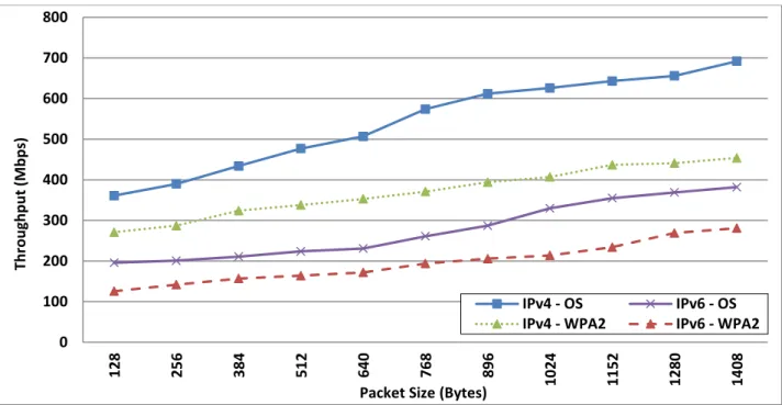
Figure 6.1: Comparison of TCP throughput for both versions of the Internet Protocol in 802.11ac WLAN, Open System vs. WPA2 security ... 50
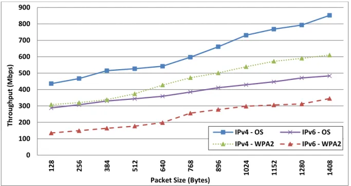
Figure 6.2: Comparison of UDP throughput for both versions of the Internet Protocol in 802.11ac WLAN, Open System vs. WPA2 security ... 51
Figure 6.3: Comparison of TCP and UDP throughput for both versions of the Internet Protocol in 802.11ac WLAN, Open System vs. WPA2 security... 52
Figure 6.4: Comparison of TCP RTT for both versions of the Internet Protocol in 802.11ac WLAN, Open System vs. WPA2 security. ... 54 Figure 6.5: Comparison of UDP RTT for both versions of the Internet Protocol in 802.11ac
Figure 6.6: Comparison of TCP and UDP RTT for both versions of the Internet Protocol in 802.11ac WLAN, Open System vs. WPA2 security ... 56 Figure 6.7: Comparison of TCP CPU Utilisation for both versions of the Internet Protocol in
802.11ac WLAN, Open System vs. WPA2 security ... 57 Figure 6.8: Comparison of UDP CPU Utilisation for both versions of the Internet Protocol in
802.11ac WLAN, Open System vs. WPA2 security ... 58 Figure 6.9: Comparison of TCP and UDP CPU Utilisation for the Internet Protocol in 802.11ac WLAN, Open System vs. WPA2 security ... 59 Figure 7.1: Comparison of TCP throughput for both versions of the Internet Protocol in
802.11ac WLAN, without human movement vs. with human movement ... 64 Figure 7.2: Comparison of UDP throughput for both versions of the Internet Protocol in
802.11ac WLAN, without human movement vs. human movement ... 65 Figure 7.3: Comparison of TCP and UDP throughput for both versions of the Internet Protocol
in 802.11ac WLAN, without human movement vs. human movement ... 66 Figure 7.4: Comparison of TCP RTT for both versions of the Internet Protocol in 802.11ac
WLAN, without human movement vs. human movement ... 67 Figure 7.5: Comparison of UDP RTT for both versions of the Internet Protocol in 802.11ac
WLAN, without human movement vs. human movement ... 68 Figure 7.6: Comparison of TCP and UDP RTT for both versions of the Internet Protocol,
without human movement vs. human movement ... 69 Figure 7.7: Comparison of TCP CPU Utilisation for both versions of the Internet Protocol in
802.11ac WLAN, without human movement vs. human movement ... 70 Figure 7.8: Comparison of UDP CPU Utilisation for both versions of the Internet Protocol in
802.11ac WLAN, without human movement vs. human movement ... 71 Figure 7.9: Comparison of TCP and UDP CPU Utilisation for both versions of the Internet
Protocol, without human movement vs. human movement ... 72 Figure 8.1: Comparison of TCP throughput for both versions of the Internet Protocol in
802.11ac WLAN, LAB005 vs. LAB003, LAB005 vs. LAB001, and LAB003 vs. LAB001 ... 77 Figure 8.2: Comparison of UDP throughput for both versions of the Internet Protocol in
802.11ac WLAN, LAB005 vs. LAB003, LAB005 vs. LAB001, and LAB003 vs. LAB001 ... 78
Figure 8.3: Comparison of TCP and UDP throughput for both versions of the Internet Protocol on LAB005, LAB003, and LAB001... 80 Figure 8.4: Comparison of TCP RTT for both versions of the Internet Protocol in 802.11ac
WLAN, LAB005 vs. LAB003, LAB005 vs. LAB001, and LAB003 vs. LAB001 ... 81 Figure 8.5: Comparison of UDP RTT for versions of the Internet Protocol in 802.11ac WLAN,
LAB005 vs. LAB003, LAB005 vs. LAB001, and LAB003 vs. LAB001. ... 83 Figure 8.6: Figure 8.6: Comparison of TCP and UDP RTT for both versions of the Internet
Protocol on LAB005, LAB003, and LAB001 ... 84 Figure 8.7: Comparison of TCP CPU Utilisation for both versions of the Internet Protocol in
802.11ac WLAN, LAB005 vs. LAB003, LAB005 vs. LAB001, and LAB003 vs. LAB001. ... 86 Figure 8.8: Comparison of UDP CPU Utilisation for both versions of the Internet Protocol in
802.11ac WLAN, LAB005 vs. LAB003, LAB005 vs. LAB001, and LAB003 vs. LAB001 ... 87 Figure 8.9: Comparison of TCP and UDP CPU Utilisation for both versions of the Internet
LIST OF TABLS
Table 2.1: Comparison between TCP and UDP. ... 15
Table 2.2: Level of attenuation of different materials. ... 24
Table 3.1: Differences between 802.11n and 802.11ac. ... 25
Table 4.1: Metrics and tools used for collecting data. ... 37
Table 5.1: Access point configuration for the test-bed... 39
Table 5.2: Software specifications. ... 40
Table 5.3: Jperf optimal values. ... 41
Table A-1: Hardware specifications of stations and network connection device. ... 99
Table A-2: Access point specifications. ... 99
LIST OF ABBREVIATIONS
ACI Adjacent Channel InterferingAP Access Point
BSS Basic Service Set BYOD Bring Your Own Device CCA Clear Channel Assessment
CGA Cryptographic Generated Address DHCP Dynamic Host Configuration Protocol DoS Denial of Service
DS Distribution System
ESS Extended Service Set FSPL Free Space Loss
GUI Graphical User Interface IBSS Independent Basic Service Set IPv4 Internet Protocol version 4 IPv6 Internet Protocol version 6 ISP Internet Service Provider LDPC Low-Density Parity Check
LOS Line Of Sight
MAC Media Access Control
MIMO Multiple-Input and Multiple-Output MIPv6 Mobile IPv6
MOV human movement
MPDU MAC Protocol Data Unit
MSS Maximum Segment Size
MU-MIMO Multi-user MIMO (MU-MIMO)
OFDM Orthogonal Frequency Division Multiplexing
OS Open System
PDA Personal Digital Assistant
PHY Physical Layer
QAM Quadrature Amplitude Modulation
RF Radio Frequency
RTS/CTS Request to Send / Clear to Send
RTT Round Trip Time
RX Receiver
SCTP Stream Control Transmission Protocol SISO Single Input, Single Output
SNR Signal-to-Noise Ratio
SS Spatial Stream
STA Station
TCP Transmission Control Protocol
TX Transmitter
WFA Wi-Fi Alliance
WLAN Wireless Local Area Network W-MOV Without human movement WPA Wi-Fi Protected Access WPA2 Wi-Fi Protected Access II
CHAPTER 1
INTRODUCTION
One of the fastest growing sectors of the telecommunication industry is wireless communication. Having a Wi-Fi network simply creates new possibilities. It provides a cheap and stress-free way to connect more than one device with a single Internet connection and allows mobility while using an Internet connection. Wireless network has the ability to expand easily by adding extra new devices without the mess of more wires and with little additional cost. The systems that offer wireless communication include cellular phones, cordless, satellites and Wireless Local Area Networks (WLANs). These systems have recently become a part of day-to-day life of almost everyone and a favourable choice for communicating. Wi-Fi network provides access from anywhere at anytime. It is not only being used as a substitute to wired systems, but it is also preferred over wired communication systems. Statistics revealed that in 2014 almost 10 billion devices were connected through wireless communication, and this figure is expected to rise to 50 billion by 2020 [1]. In 2011, shipments of Wi-Fi certified microchips surpassed one billion units and are expected to be more than 2.5 billion units per year by 2016 [2].
The IEEE 802.11 standard is commonly used for Wi-Fi communications. All the latest Internet devices including smartphones, laptops, and PDAs (personal digital assistant) have WLAN chipsets built-in to support this standard. The latest standard IEEE 802.11ac provides significantly higher data rates, client capacity, and density than previous standards and directly addresses the user demands generated by the explosion of mobile and Bring Your Own Device (BYOD) [3].
The existing methods used for securing wireless networks are based on modern cryptography techniques. Issues with the initial WEP encryption led to the introduction of new encryption technology to enhance the security from wireless penetration including WPA and WPA2. However, the implementation of these security methods has had a negative effect on the WLAN performance. The security encryption adds extra bits on the packet size that can reduce the data transfer rate [4].
Wireless networks have the capability to sense radio signals as long as they are in the range of radio signals’ coverage. One of the essential factors that impacts on the performance on
Chapter 1: Introduction
from propagation through walls or distorted from dispersion wall materials. Strong signal and data transmission rates can be significantly decreased when radio waves are refracted by different objects in a propagation environment. Interference of radio waves occurring in a dense environment can cause network issues, where increasing packets drop and delay over a Wi-Fi network. Human shadowing has a negative impact on WLAN performance in an indoor environment. Receiving signal strength is even influenced by the human body in some cases where the receiver gains the signals from multiple transmitters [5].
Recently, IPv4 is the most extensively adopted network layer protocol in WLANs. IPv4 provides 232 addresses, which cause a shortage in address space leasing. IPv6 is the latest technology and is claimed to outperform IPv4 by allowing 2128 addresses. IPv6 is advantageous over IPv4 in many aspects; it provides more effective routing, better packet processing, better mobility, improved network autoconfiguration and more security [6].
Transmission Control Protocol (TCP) and User Datagram Protocol (UDP) are used at transport layer. TCP establish a connection between two nodes before sending any data to ensures the secure and organised streaming of Bytes from a server to the receiver and the other way around. UDP is Connectionless, which delivers packets to another node even if there is no connection. Hence, the service provided by UDP is unreliable and it is possible that while using this service, the datagrams can get out of order or even go missing without one’s knowledge [7].
In this thesis, the performance of IEEE 802.11ac (Windows 8.1 - Windows Server 2012) WLAN was evaluated using TCP and UDP for both versions of the Internet Protocol (IPv4, IPv6). Performance experiments were conducted in three different network scenarios, namely, shadowing effects in laboratory environment, the impact of implementing WPA2 security encryption, and the effect of human movement in an indoor environment. In each of the three contexts, various networks have been implemented on test-beds and then performance-related metrics (throughput, round trip time, CPU utilisation) were measured and analysed. It was envisaged that this undertaking would lead to a better understanding of 802.11ac network performance behaviours in a new IPv6 environment.
1.1 Thesis Objectives
The primary focus of this thesis is to evaluate the new IEEE 802.11ac WLAN’s performance characteristics and produce new results. In each of the three scenarios explained above, various network test-beds have been implemented to evaluate protocol behaviour with regard
Chapter 1: Introduction
to throughput, round trip time (RTT) and CPU utilisation. Thus, the core objectives of this thesis are:
1. To quantify the impact of implementing WPA2 encryption on the performance of wireless networks 802.11ac, taking the measurement for throughput, round trip time, and CPU utilisation.
2. To investigate the impact of shadowing (walls) on 802.11ac WLAN link in an obstructed environment. We evaluate the relationship between shadowing and Wi-Fi link throughput, delay, and CPU utilisation through measurements. This information will help with identifying the optimal locations for APs placement.
3. To investigate the impact of human movement on 802.11ac Wi-Fi link throughput, delay, and CPU utilisation in an indoor propagation environment and provide a comparative analysis to identify if there is any the significant difference in Wi-Fi performance compared to no human obstacle.
4. To examine the performance of 802.11ac WLANs in IPv6 vs IPv4 environment. 5. To examine the performance of 802.11ac WLANs in TCP vs UDP environment.
The thesis evaluation will enhance knowledge related to IEEE 802.11ac WLAN’s performance. This will be very useful for expert practitioners who may be determining the best choice to select of this technology they are to implement in their network infrastructures.
1.2 Related Work
In this section, a brief review of the existing literature on the evaluation of 802.11ac wireless networks is presented. However, some research that is relevant to the thesis objectives from IEEE 802.11 g and n are added as related work, especially where 802.11ac data was not available.
In 2015, S. Narayan, et al. [8] carried out a comparative peer-to-peer performance evaluation in 802.11ac and 802.11n WLANs for both versions of the Internet Protocol on Windows 7 operating system. Router channel width settings were configured at 20MHz and 40MHz to 2.4GHz and 5GHz bands respectively in 11n, whereas 11ac located at 80MHz channel width. The outcomes noted that on average, 802.11ac provides a higher throughput than WLAN counterpart (802.11n) for both versions of the Internet Protocol. TCP throughput for 11n in
Chapter 1: Introduction
and IPv6. Both WLAN (11ac, 11n) have a highest jitter values by applying IPv4 compared with applying IPv6.
In 2015, Y. Zeng, et al. [9] measured the performance of 802.11ac networks. The impact of various parameters including distance, power consumption, and interference on throughput was measured with varied packet sizes in indoor environments. UDP throughput declined significantly by 91% (585 Mbps) when the receiver was located 90 metres away from the Access Point (AP) in denser network (contains 5 AP and 13 clients) with fixed location to achieve the maximum distance in indoor environments. The experiment was replicated for 802.11n, which was operating in the 5GHz band. Results showed that on the average the UDP throughput is almost doubled on 802.11ac compared with 802.11n. Increasing the number of Spatial Stream (SS) from 1 to 6 provides a lower power consumption by 40% (20 Milliwatt) and increases the throughput to 350 Mbps, which can be achieved by doubling the channel width from 40MHz to 80MHz. 802.11ac channel widths should be selected wisely because the capability of 802.11a/n to operate at 40/20 MHz in the 5GHz band, causes interference to an 802.11ac Access Point.
In 2015, R. S. Cheng, et al. [10] investigated the performance of the emerging communication protocol called Stream Control Transmission Protocol (SCTP) over 802.11ac WLANs by implementing analytical modelling. The protocol has been developed to improve the communication quality in Wi-Fi networks. The results showed that the SCTP outperforms the Transmission Control Protocol (TCP). SCTP offers higher throughput because it utilises a higher number of streams by reducing the delay time. SCTP over the 802.11ac network has faster and more stable performance compared with previous IEEE 802.11 standards.
In 2015, F. Siddiqui et al. [11] addressed the issues that restrict IEEE 802.11ac from achieving the maximum throughput beyond 1Gbps. The study focused on the performance of several 11ac new features by implementing a test-bed of devices supporting 802.11ac draft. The results showed that to obtain the highest data rates, all the spatial streams that are installed at the Access Point should be utilised by the client device. Also, use of 80MHz and 160MHz channel widths is more susceptible to radio frequency interference than 20/40MHz. In addition, advanced modulation formats (256-QAM) can be utilised in a situation that has a high Signal-to-Noise ratio (SNR), or low radio frequency interference. Finally, beamforming technology can work well when AP is close to the client device area.
In 2014, M. D. Dianu, et al. [12] examined the effect of distance, propagation environments, and Wi-Fi interference on 802.11ac WLANs performance in an indoor environment. It was concluded that the maximum UDP throughput achievable in the typical environment was 700
Chapter 1: Introduction
Mbps at channel width 80MHz. However, the throughput dropped significantly by 87.12% (90.1 Mbps) when the receiver (RX) was placed 24.3 metres away from the transmitter (TX) and environmental obstructions were a supporting concrete wall and three soft partitions. To measure the impact of legacy standard interference, IEEE 802.11n WLAN was set up and placed close to the TX or on the RX. Results showed that the UDP data rate of the 802.11ac WLAN is significantly reduced when 11n network sends and receives the packet size simultaneously at a same 11ac channel width (40MHz).
In 2014, M. O. Demir, et al. [13] carried out a comparative examination of IEEE 802.11ac WLANs with regards to the power consumption of the access point during transfer data in server-client LANs test-bed. Data was gathered by considering various parameters like packet size, bandwidth channel and transmit energy level. Results showed that the highest throughput was achieved when all packet sizes (64 Byte to 1470 Byte) were sent in channel width at 80 MHz, which also the highest energy consumed. The energy efficiency was achieved when short packet lengths (64 Byte to 256 Byte) were sent in channel width at 20MHz, and long packets (1024 Byte to 1470 Byte) were sent in channel width at 80MHz. The transmit power level configuration has a tiny effect in terms of power consumption.
In 2014, G. Patwardhan, et al. [14] evaluated the vulnerability of IEEE 802.11ac beamforming by a new type of jamming attacks. The authors conducted the experiment by using jammer and sniffer devices, which were installed between client and access point in 802.11ac draft. Results showed that jamming attack has a remarkable effect on beamforming in terms of throughput degradation with 90.62% (724.5Mbps). Also, the attack reduced data rate transferred to 55.03% (478Mbps) on 802.11ac Multiple-Input and Multiple-Output (MU-MIMO) feature.
In 2014, A. Stelter, et al. [15] offered a new dynamic channel access method that increases the throughput by utilising 80/160MHz channel widths over 802.11ac WLANs. The legacy 802.11a/n signals located at 20/40MHz channels can occupy a non-primary 20MHz channel width over 80MHz 802.11ac station during the clear channel assessment (CCA). The proposed method has the ability to remove the adjacent channel interfering (ACI) signal from the received 11ac signal, which enhances throughput increment.
In 2011, M. Park, et al. [16] carried out a simulation experiment to study the effect of using the primary and secondary channel bandwidths between 20, 40, and 80MHz for the first wave of 802.11ac (draft). The results of the experiment showed that 20MHz channel width throughput was better than the static 80MHz by 85% when the secondary channels are operated by 20MHz
Chapter 1: Introduction
recommended option to access point configuration. The secondary channel plays an important role in reducing collisions between the 802.11ac and IEEE 802.11a and 11n.
In 2011, E. H. Ong, et al. [17] carried out a comparative evaluation of IEEE 802.11ac draft and IEEE 802.11n WLANs at three channel widths (40/80/160MHz) in terms of higher data rates. The performance analysis showed that 11ac at 80MHz channel width with single input, single output (SISO) outperforms 802.11n configured at 40MHz with 2×2 input and multiple-output (MIMO) by 28% higher throughput. Maximum throughput in 160MHz channel widths with SISO does not measure well with the bandwidth increment.
IEEE 802.11 n and g are presented as related works in the following part of the literature review because there is no research that covers the effect of people movement and implementing WPA2 security mechanisms on the 802.11c WLANs.
In 2013, N. I. Sarkar, et al. [18] carried out an investigation of people movement effectiveness against Wi-Fi link throughput using IEEE802.11g in various indoor environments by using radio propagation measurements. The measurements considered both the random and straight line patterns of people movement. Findings of this investigation showed that the human movement had a negative impact on transfer data rate over 802.11ac WLANs. The average of fixed human and random human movement throughput in different obstruction environments decreased to 7.88% (1.92Mbps) and 8.82% (2.15Mbps) respectively, compared to without people movement over 11ac network. The pattern of people movement has a tiny impact on throughput degradation over 11ac Wi-Fi network.
In 2012, S. Japertas, et al. [19] conducted the experimental study of the IEEE 802.11g and n signal propagation in an indoor environment. The results showed that 802.11n has stronger waveguide effect than the 802.11g in free-space with no obstacles. Single strength for 11n and 11g were spotted at 23dBm and 8dBm respectively when the receiver was located 37 metres away from the transmitter. The partition wall significantly impacted on signals level. The result showed that when the wall is present, the signal power is much lower for 11g than 11n. The average of 11n and 11g signal absorption increased to 21.2dBm and 24dBm respectively when the receiver was located 30 metres away from the transmitter.
In 2011, S.S. Pang et al. [20] conducted a peer-to-peer performance evaluation for 802.11n Wi-Fi network for versions of Internet Protocol by applying WPA2 security mechanism. Results showed that the TCP throughput WPA2 encryption enabled for Windows 7 decreased by 6.21% and 3.11% for IPv4 and IPv6 respectively compared with disabling WPA2 security on WLAN. In contrast, the TCP throughput with WPA2 encryption enabled for Fedora 12 operating system
Chapter 1: Introduction
declined by 5.55% and 3.8% for IPv4 and IPv6 respectively compared to the open system network.
In 2011, Kolahi et al. [21] examined the effect of applying WPA2 encryption on UDP (throughput, RTT) on 802.11n WLANs for both versions of the Internet Protocol. Client-server network (Windows 7-Windows Server 2008) were installed as operating systems. Implementing WPA2 for IPv4 decreased UDP throughput an average of approximately 24.33% (29.4Mbps) less than open systems. For IPv6, UDP throughput dropped at least 10.14% (11.15Mbps), compared to no security enabled.
In 2009, Kolahi et al. [22] analysed the effect of enabling WPA2 encryption on TCP throughput for both versions of the Internet Protocol on 802.11n Wi-Fi network. Three Windows operating systems were installed into two client-server networks (Vista - Server 2008 and XP - Server 2008). XP WLAN with no security implementing gained in an average about 7.07% more TCP throughput than enabling WPA2 for IPv4, and 5.42% more TCP throughput for IPv6. Implementing WPA2 security has more influence over Vista compared to XP. In Vista WLAN with WPA2 encryption enabled reduced the TCP throughput for IPv4 and IPv6 by an average to 9.39% and 17.02% less than applying these protocols on WLAN without WPA2 encryption enabled.
In 2007, Filho et al. [23] carried out a performance evaluation of IEEE 802.11g WLANs by using two security mechanisms with different cryptographic key lengths. Their results showed that WEP-128 has a significant effect on TCP in terms of throughput degradation with 20% whilst applying WEP-64 decreased UDP throughput to 8%. WPA encryption has the lowest level of influence with 14% and 6% for TCP and UDP throughput.
In 2006, Ezedin et al. [24] investigated the effect of security encryption on IEEE 802.11g WLANs performance by implementing different WEP encryption keys on TCP and UDP protocols. Results showed that implementing WEP security for key size 64-bit and 128-bit increased the TCP throughput degradation from 1.9% to 4.5% respectively. The degradation of the throughput for UDP increased slightly with WEP 64-bit by 0.23% compared to 6% with WEP 128-bit.
1.3 Thesis Contributions
Chapter 1: Introduction
1. The comparison between the actual achievable throughput in the test-bed and the theoretical maximum throughput of 802.11ac.
2. The effect of obstructed environment in an office environment on the performance of 802.11ac.
3. The effect of implementing WPA2 encryption on the performance of 802.11ac WLANs. 4. The effect of human movement on 802.11ac WLANs performance in Indoor propagation
environments.
5. The performance of 802.11ac WLAN in IPv6 compared to IPv4. 6. The performance of 802.11ac WLAN in TCP compared to UDP.
The presented contents will be beneficial to academic researchers and to businesses wanting to get the best performance out of IEEE 802.11ac standard.
1.4 Structure of the Thesis
The thesis is organised as follows: Chapter one contains an introduction, which briefly mentions the importance of wireless and issues that confront this technology, and the objectives behind this study. This is followed by the contributions of this research and concludes by highlighting other research works with a similar focus.
Chapter two provides background information on key concepts relating to the topic.
Chapter three covers the details of an IEEE 802.11ac standard. This chapter explains the core technology and features of 802.11ac.
Chapter four covers the methodologies that were employed for this thesis. This chapter also displays the methods of gathering data in laboratory experiments.
Chapter five includes a detailed explanation of the network diagram and the specification of all hardware and software used in the test bed. It also contains hardware and software configurations, commands and monitoring tools used during the test.
Chapters six, seven and eight cover the performance evaluation of 802.11ac WLANs in three scenarios, namely, the impact of implementing WPA2 encryption and the effect of shadowing in a laboratory environment, and the effects of human movement in an indoor environment. Each chapter analyses the results with regards to the performance of TCP and UDP for both IPv4 and IPv6 protocol mechanisms.
Chapter nine is the final chapter, which covers the conclusion, discussion, and directions for future works.
Chapter 1: Introduction
1.5 Chapter Summary
This chapter provided an introduction to the thesis. Thesis objectives, contributions, and related works were presented. It highlighted areas where new results were obtained to get better understanding of 802.11ac standard. In this thesis, new results were obtained on the effect of IPv6, WPA2 security, shadowing, and human movement in Windows 8.1- Server 2012 environment WLAN.
CHAPTER 2
BACKGROUND TECHNOLOGIES
This chapter provides a background of wireless technology features. Section 2.1 gives an overview of IEEE 802.11 standards. Section 2.2 provides the details of the different types of 802.11 architecture. Section 2.3 describes the internet model more focused on data communication and internet protocols. Section 2.4 describes physical and MAC layers of 802.11ac. Section 2.5 covers wireless security protocols. Final section describes wireless radio propagation characteristics.
2.1 An Overview of IEEE 802.11
The WLAN has experienced an exponential growth in the last decade with the increasing number of devices that support different 802.11 standards. The technology development of microchip and IEEE 802.11 standards have led to decreasing the cost dramatically, which has boosted user adoption of Wi-Fi network technology. In 1999, due to the increasing commercial demand, Wi-Fi Alliance (WFA) was founded. It certifies interoperability among IEEE 802.11 devices from various producers through testing [3]. The vigorous upsurge in the data rate with the modification is shown in Figure 2.1.
In October 1997, the IEEE 802.11 standard was published. The published standard covers MAC protocol as well as the physical layer. The initially published standard provided low data rates only comprising of a speed between 1 and 2 Mbps at 2.4GHz ISM band [25].
In October 1999, both IEEE 802.11a and 802.11b modifications were sanctioned by the IEEE 802.11 committee. The IEEE 802.11a functions at 5 GHz unlicensed band and allows a speed of up to 54 Mbps. 802.11a get frequency less prone to interference because it operates at 5GHz band, which has uncrowded frequencies and a shorter coverage range compared to 2.4GHz. IEEE 802.11b has a maximum throughput to 11Mbps, where it operates at 2.4GHz band. 802.11b covers more transfer range than 802.11a but it suffers from high Wi-Fi interference [26].
In June 2003, due to high demand for using different wireless technologies, the 802.11g emerged to improve data transfer speed (54Mbps), where it has enabled backward compatibility with 802.11b. But a major downfall to this protocol is that it experiences the same
Chapter 2: Background Technologies
interference problems as 802.11b where devices operate at a much crowded band (2.4GHz) [27].
The signal strength and speed of the wireless connections is very important in large growing companies. For this reason, in 2009 IEEE improved wireless standards and produced 802.11n. The 802.11n protocol involves modifications in the standard like adding a multi-input-multi-output antenna (MIMO), which allows the receiver antennas to combine data streams that arrive from different paths at the same time. 802.11n operates in both 2.4GHz and 5GHz frequencies bands. Using 5GHz band has improved a great deal providing a higher throughput due to less crowded frequencies, whereas 2.4GHz extends Wi-Fi range more. One of the major advancements in the new protocol is its enhanced capability of handling data as bandwidth was increased theoretically up to 600Mbps in case of using 4x4 MIMO at 40 MHz channel [28]. With the goal of increasing the performance of WLANs compared to wired networks, in December 2013 the IEEE 802 standards committee formed two new Task Groups (TGs), namely 11ac and 11ad. The 11ac standard functions in the band of 5GHz only and does not support the band of 2.4GHz. Theoretically, it is capable of allowing a speed up to1.3 Gbps. The new provisions were assembled on the 11n standard. The bandwidth of 802.11ac channel was increased from 40MHz to 80 or even 160MHz. It also involves the advanced order of modulation system (256-QAM) and other improved features such as Beamforming, Multi-User Multiple Input Multiple Output (MU-MIMO) with up to 8 spatial streams, etc. [29]. All features will be discussed in details on the next chapter. IEEE 802.11ac is recognised as the most modern wireless standard; this thesis attempts to investigate the different WLANs performance actors based on this latest standard.
IEEE 802.11ad is also emerging technology and an improvement to the 802.11n WLAN standard. It operates in the unlicensed and globally accessible 60GHz band. 802.11ad consumes a low power, and produces very high throughput, up to 7Gbps. The standard has a very short distance of about 1 to 10 metres. At 60GHz, the propagation behaviour increases signal attenuation and leads to difficulty penetrating walls [30].
Chapter 2: Background Technologies
Figure 2.1: Increase in 802.11 Physical data rate [31]
2.2 IEEE 802.11 Architecture
Basic Service Set (BSS) is more than one 802.11 devices (stations) that communicate with each other by connecting to a single access point. The simplest form of BSS is called Independent Basic Service Set (IBSS), where stations can communicate with each other without using an access point. A BSS is built around an access point, which is known as an infrastructure BSS (Figure 2.2). These Infrastructure BSSs can be interconnected through their access points via a Distribution System (DS). Extended Service Set (ESS) is an interconnection of BSSs, which is connected via a DS. The stations within the ESS are able to access each other directly through the MAC layer [32].
Chapter 2: Background Technologies
2.3 Internet Model (TCP/IP protocol)
Internet Protocol (IP) or Transmission Control Protocol (TCP) is the most commonly used protocol suite for Internet. TCP/IP offers end-to-end connectivity protocol. It specifies the packaging, addressing, transition, route and receiving of the data at the end. As per the scope of networking, four abstraction layers are used to perform all these functions by sorting out the protocols as per requirement. From the highest to lower, the layers are the application layer, which is responsible for the process-to-process application data exchange; the transport layer which mainly handles host-to-host communications; the Internet layer is responsible for connecting the hosts across different networks; and the link layer, which contains the communication technology required for a single network segment [33].
Figure 2.3: TCP/IP protocol structure [34]
2.3.1 Transport Layer
Transport Layer Protocol is an important part of the protocol hierarchy, which is necessary for the provision of end-to-end communication between the hosts over the network. Several features offers by Transport Layer Protocols are: congestion control, reliability, in-sequence delivery, control of flow, etc. These features ensure efficient performance and high quality services for the communication network [35]. It is important to make the correct choice of transport layer protocol for multimedia communication as this can significantly improve the quality requirements of multimedia, i.e. jitter rate, reduced delay, packet loss, efficient throughput, etc. [36]. Following are some of the widely used transport layer protocols:
Chapter 2: Background Technologies
User Datagram Protocol (UDP)
UDP is the most basic form of transport layer with no reliability for efficient and secure transmission of the packets. However, it is capable of multitasking and broadcasting. UDP provides the best choice when caring about the transmission time rather than reliable transmission. Additionally, there is no congestion control mechanism offers by UDP. The congestion control is important to prevent the network from being congested, which leads to reduced efficiency and performance [37].
Transmission Control Protocol (TCP)
TCP is connection-printed that offers an efficient congestion control mechanism as well as a positive acknowledgment system [37]. It is an extensively used protocol because of the capability of ensuring the reliability regardless of the type of lower layer of network. TCP is stream-oriented, which means the TCP protocol entities exchange streams of data. When transmitting using the TCP protocol, each byte in the communication process has its own sequence number to ensure that all data in motion arrives at the destination intact. TCP is also known as robust protocol because of its adaptability in various networking conditions. However, there are certain reasons that can lead to a drop in the TCP packets over the wireless network. Some of these factors are: higher rate of error, and frequent disconnection of the network [38].
Comparison of TCP and UDP
All transport protocols have overheads. The overhead is information that is encapsulated with transmitted data and contains sources and destinations of the packet. The header format for UDP protocol contains 4 fields; each of them is 2 Bytes in the length (8 Bytes overhead per segment). These fields represent a Protocol Control Information (PCI), which includes [39]:
o Source Port: specify the station (STA) port (Optional). o Destination Port: specify the client port (Required). o UDP length: identify the entire datagram length.
o UDP Checksum: check and correct the errors for the header and transmitted data, it is optional in IPv4 and required in IPv6.
The header format for TCP protocol contains 9 fields with a total length of 20 Bytes. Source port, destination port and TCP Checksum are functionally similar to UDP header fields; each of them has 2 Bytes. Sequence number field (4 Bytes length) ensures the reliable connection.
Chapter 2: Background Technologies
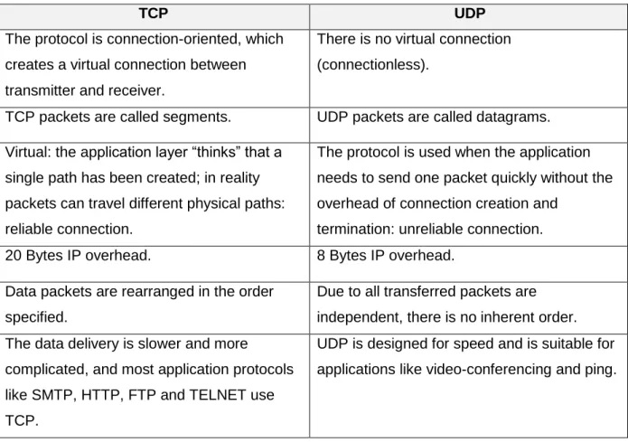
The 2 Bytes window field accommodates the length of Bytes that the client can receive. The remaining fields include Hlen, Flags, Acknowledgment number, and Urgent pointer [39]. Table 2.1 gives an overview of TCP and UDP protocols and Figure 2.3 illustrates a comparison between data packets.
TCP UDP
The protocol is connection-oriented, which creates a virtual connection between transmitter and receiver.
There is no virtual connection (connectionless).
TCP packets are called segments. UDP packets are called datagrams. Virtual: the application layer “thinks” that a
single path has been created; in reality packets can travel different physical paths: reliable connection.
The protocol is used when the application needs to send one packet quickly without the overhead of connection creation and
termination: unreliable connection.
20 Bytes IP overhead. 8 Bytes IP overhead.
Data packets are rearranged in the order specified.
Due to all transferred packets are independent, there is no inherent order. The data delivery is slower and more
complicated, and most application protocols like SMTP, HTTP, FTP and TELNET use TCP.
UDP is designed for speed and is suitable for applications like video-conferencing and ping.
Chapter 2: Background Technologies
2.3.2 IP Header
“Next Node” is determined by the information extracted from the IP datagram through the forwarding protocol of the router. Selected fields of the header of IP datagram hold the required information. IP header information is combined with the routing table in order to extract meaningful information by the router [41]. Currently, two versions of IP Protocols are being used extensively, i.e. IPv4 (version 4) and IPv6 (version 6).
Internet Protocol Version 4 (IPv4)
Amongst TCP/IP Protocol Suite, Internet Protocol (IP) is considered one of the essential protocols. In Open Systems Interconnection Model (OSI Model), this protocol is implemented at the Network Layer, while in the TCP/IP model it works at the Internet Layer. In both of these models, this protocol is responsible for identifying the authorised hosts on the basis of their logical addresses [41]. IPv4 provides 232 addresses containing both network and host identifier. IP Payload is the encapsulated data, whereas IP header contains all information that important for the data packet being transmitted [42].
Internet Protocol Version 6 (IPv6)
Compared to header of IPv4, the IPv6 is less complex. Several fields and fragments have been removed from the IPv6 header while an extension has been made with addition of fields for fragmentation and Checksum. With these modifications, the IPv6 Header now has a fixed length of 40 bits. The header size is increased because the addressing mechanism rose to 2128 addresses. Overall, the IPv6 header is comparatively simple, and is, in theory, much more efficient than its counterpart [42].
Comparison of IPv4 and IPv6
IPv6 is an evolved version of IPv4 that focuses on the shortcomings and limitations of IPv4. The following section will present an overview of some of the key features of IPv6 that help overcome the issues of IPv4.
The IP Headers
The increase of IPv6 header size is mainly due to the movement away from 32-bit to 128-bit addressing. The number of fields has reduced to 8 in the IPv6 header instead of 12 in the IPv4 header. The source and destination addresses in the IPv6 header are 4 times longer than the IPv4 header. IPv6 contains one or more extension header to provide both flexibility and
Chapter 2: Background Technologies
efficiency by providing information that is needed for common functions such as fragmenting. There are a number of fields that have been eliminated in the IPv6 header such as Internet Header Length and Header Checksum, or replaced such as Type of Service to Traffic Class field. The entire IPv6 overhead is of 40 Bytes fixed length compared to 20 Bytes long for IPv4 packet overhead [42].
Figure 2.5: Changes and relationship between IPv4 and IPv6 header [41] Extended Address Space
IPv6 has a hexadecimal address structure that allows it to have almost 7.9x1028 more unique addresses as compared to IPv4. The extended addresses is a crucial feature considering the exponential growth of the Internet as new online products are increasingly used such as mobile platforms, tablets, etc. These demands require more efficient IP referencing embedded models. Thus, IPv6 address space will be needed to establish a sufficiently efficient Internet gateway [43].
Efficient Routing
IPv6 shrinks the size of routing tables and promotes routing efficiency. IPv6 provides Internet Service Providers (ISPs) to combine the prefixes that belong of their clients' network into one prefix and advertise this prefix to the IPv6 Internet [43].
Better Mobility
Chapter 2: Background Technologies
Improved Security
IPv6 offers several security enhancements that were not offers by IPv4. The first action made by the network attackers is to observe the ports in order to collect all possible information related to the network that has to be attacked. Since there were very limited ports in IPv4, this was done by attackers very easily. However, IPv6 has made this network sniffing more difficult because of increased time required for scanning or sniffing a huge number of ports. Thus, reducing the security risks significantly. IPv6 also creates the Cryptographic Generated Address (CGA) for better security. According to the mechanism of CGA, a public signature key is assigned to each IPv6 address. This public key can be used by the authorised user as proof of being the authorised owner of a respective address [43].
Neighbor Discovery
MAC address is required whenever a system sends IPv6 packet to another system that is associated with the same subnet. Mechanism for Neighbor discovery is capable of letting the systems identify the MAC addresses of each other. Neighbor solicitation is sent to the solicited node address that refers to the targeted IPv6 address [45].
Duplicate Address Detection
A Duplicate Address Detection mechanism is introduced for IPv6 addresses in order to avoid assigning the same address to two different systems [44].
Autoconfiguration
In a large network environment, autoconfiguration simplifies the network node configuration by automating the process. Stateless host automatic configuration is embedded in the new version and this simplifies the Dynamic Host Configuration Protocol (DHCP) configuration, which assigns IP addresses to each host [43].
2.3.4 The Data Link Layer
The main tasks of this layer are: division of the data stream into small data frames, addition of physical addresses on these frames, imposition of a flow control procedure that tends to protect the overwhelming of the receiver, making the data transmission reliable by detecting the lost and damaged data, and also controlling the access on those links in which two or more devices are associated to the same link [46].
Chapter 2: Background Technologies
2.4 The IEEE 802.11 Standard
The IEEE 802.11 standard features multiple physical layers referred as PHYs and for wireless local area networking, it has a common medium access control (MAC) layer [47].
2.4.1 802.11 MAC Layer
Medium Access Control (MAC) mechanism protects the multiple nodes from accessing the same channel at the same time. Every node starts listening on a desired channel to detect whether the channel is ideal or busy before it transmits a packet. If the channel is idle during the back-off time, the node transmits the packet and resets the back-off window size to minimum. Otherwise, it doubles the back-off window size, waits until the channel is idle [47].
2.4.2 802.11 Physical Layer (PHY)
Modulation techniques and data coding are the most important parts of the 802.11 physical layer. During the modulation process, digital information symbol turns into a steadily low-frequency signal form. Later on, low low-frequency signal is transmitted over the high low-frequency. Design of Modulation Schemes focuses on the implementation complexity and bandwidth efficiency. Bandwidth directly affects the function of a wireless communication system [48].
2.5 Wireless Security Protocols
Wireless communication security is more of a concern than wired since there is no inherent physical protection between communicating devices. The physical connection is replaced by logical associations using radio frequency, which by nature uses broadcast for transmission. In such an environment common security threats, such as eavesdropping, injecting bogus messages, jamming, and Denial of Service (DoS) can be easily mounted. For protection, it is important to ensure confidentiality, authenticity and integrity of the data transmitted through wireless mediums. For this purpose, special wireless security protocols were established [49].
2.5.1 Wired Equivalent Privacy (WEP)
IEEE 802.11 attempted to secure wireless transmission by creating WEP encryption. Its primary objective was to make wireless transmission as secure as wired transmission. WEP is
Chapter 2: Background Technologies
only authorised users on the network. This authentication was done through a challenge-response protocol that involved very simple processing [50]. The WEP supports two keys of length (64-bit and 128-bit). The 128-bit WEP key is a more sophisticated encryption compared with 64-bit WEP. It uses a 104-bit as a secret key, and 24-bit Initialization Vector (IV), which is not under user control whereas 64-bit WEP use a 40-bit as a secret key, and 24-bit IV. The main problems with WEP are having weak encryption keys that can be broken by a passive attack, and it also provides a single-way authentication, which can be easily intercepted by a rogue station [50].
2.5.2 Wi-Fi Protected Access (WPA)
WPA encryption method was emerged to handle the WEP vulnerabilities. WPA was enhanced and modified to overcome these issues. For instance, Encrypted Message Integrity Checks (MIC) were integrated within the WPA to restrict any attacker from capturing or altering any data packet being transmitted. MIC further reduces the threat of DoS and spoofing. Despite significant improvements in WPA over WEP, the new WLAN security protocol has already been exploited. Different methods have been developed to crack a WPA encryption. Finally it was confirmed that almost all data packet transmitting towards a WPA security enabled on WLAN client could be decrypted by using spoofing packets in the data stream [50].
2.5.3 Wi-Fi Protected Access 2
WPA2 have been introduced with efficient wireless encryption algorithms. It is capable of providing a better data protection and enhanced access control for the network layers compared to WEP and WPA [50]. WPA2 also supports WPA along with several other features and benefits. WPA2 ensures stronger authentication and processes of encryption for ad-hoc and infrastructural implementations. On the other hand, WPA only supported encryption for infrastructural implementation. Key catching mechanism is also implemented by WPA2 that helps in reducing the overhead of network nodes between the access points. It also supports pre-authentication required for authenticated exchange between the wireless node and the access point [51].
2.5.4 Security Overheads
The protocol overhead is the necessary information that additionally attached to the payload to successfully exchange data packages in a communication system. This information may contain the source and destination of a message or determine the beginning and end of a
Chapter 2: Background Technologies
message. Any WEP frame has a constant 8 Bytes and followed by the payload. The further fields contain required information to decrypt the message at the receiver side. Whenever body frame size is shorter, the WEP overload becomes a significant weight. The WPA overheads have 20 Bytes occupied, which are 2.5 times more than classical WEP, whereas the total overhead of WPA2 is 16 Bytes [52]. In this thesis, WPA2 was selected in WLAN test-bed.
2.6 Wireless Radio Propagation Characteristics
It is important to understand the propagation of radio waves in order to empathise how physical environment affects the wireless transmission. Environment for the radio propagation is a significant factor that can impact the throughput performance over the Wi-Fi networks. Therefore, it is important to research these factors in order to design and deploy an efficient transmission mechanism for WLANs. Radio propagation in an indoor environment is influenced by building walls and floors, and modelling these factors presents an image of how interference might be attenuated via planning service deployments or even infrastructure modifications [53]. In such a model, a signal is transmitted through an antenna for three distinct routes i.e. ground waves, sky waves, and line of sight (LOS). One of these three transmissions will dominate the remaining based on their frequencies. However it must be understood that the received signal in any form is always different from the signal sent due to various impairments [54]. Following are some of the transmission impairments that are most likely to impact LOS transmission:
2.6.1 Attenuation
Attenuation is referred to any loss of signal power (strength), which can be influenced by the distance over any wave propagate. A logarithmic calculation (path loss) is a standard way to measure signal strength [54].
2.6.2 Free Space Loss
This is the dispersion of the signals over the distance during any wireless communication. A reduction of signal power that will be received by the antenna at reception is based on how far the reception is. Free Space Loss (FSPL) occurs when the transmitting signals are ideally a radiating point source in space without obstacles nearby that might cause reflection or diffraction [54].
Chapter 2: Background Technologies
2.6.3 Fading
Fading is described as variation in the time of received signal power due to the changes in the medium or path of the transmission. During the designing of the communication system, fading is considered the most challenging technical issue. Generally, it is atmospheric conditions that influenced the fading in a fixed environment. However, in the case of the mobile environment, the impacting factors tend to change with time and motion of the reception and sending antennas, which as a result, becomes even more complex [55].
2.6.4 Multipath
Multipath is referred to as the propagation in which the reception antenna receives the signal from two or more different paths. One of these signals is direct while the others are reflected with an opposite phase. This can lead to mutual cancellation of signals, therefore, causing significant loss of signals. Based on the path and distance of the direct and reflected waves, the composite signal can either be amplified or smaller than the actual signal [55].
Multipath is commonly observed in indoor areas where several metallic surfaces are present. The following figure shows the mechanisms that can result in multipath propagation:
Figure 2.6: Types of propagation mechanism [53]
Reflection
Reflection usually takes place when a large dimensional object becomes an obstacle during the transmission. Such objects can be walls, cabinets, furniture, etc. These mediums tend to
Chapter 2: Background Technologies
absorb some of the signals that were being transmitted, while the remaining are reflected off the surface [53].
Scattering
Scattering occurs when several small sized objects become an obstacle for the transmitted signals. These objects can be bushes, cabinets, trees, etc. These objects tend to scatter the reflected energy in several directions before they are received by the receiver [53].
Diffraction
Diffraction takes place when the obstacles have sharp edges that can produce a secondary wave, which may bend around the obstruction. Similar to the reflection, the phenomenon of diffraction is also influenced by the physical features of the hurdles. In case of several obstructions, the waves are diffracted. However, they may still have enough strength to combine into a meaningful signal [53].
The above stated effects of propagation can have a significant impact on the performance of the system based on various medium and condition related features. Usually, diffraction and scattering are not major issues with respect to a sufficient LOS distance between the transmission and reception antenna. However, reflection can be a major issue in this case. Furthermore, in the absence of LOS, diffraction and scattering becomes the basic method of reception of the signals [56].
Refraction
Refraction is described as the variation in the direction of the electromagnetic waves that results in the variations in velocity of propagative mediums through which the signals are passing. This can create a condition where very little or no signal reaches the reception antenna [56].
Noise
In a case of any transmission, a transmitted signal will be delivered with a sort of distortion that is enforced by wave propagation, these undesired signals are known noise or interference, which is considered a significant factor limiting the performance of communications systems [56].
Chapter 2: Background Technologies
Absorption
Absorption occurs when signal is lost while passing through different obstacles or mediums. During absorption, the form of some signals turns into another form of energy, which is mostly heat (thermal energy). Any material that is not transparent to the electromagnetic signals can result in absorption of the transferred signal. The strength of signal mainly depends on characteristics of a medium that the transmitted signal can pass through [57].
Table 2.2: level of attenuation of different materials [57]
2.7 Chapter Summary
This chapter covered the background on wireless technology. It also spotlighted the issues that influenced of the performance WLANs, which are radio propagation characteristics and packet overheads. It also provided information about IPv4, IPv6, TCP, UDP, and WPA2.
The next chapter provides the details of IEEE 802.11ac, which is the wireless LAN standard used to evaluate in this study.
CHAPTER 3
IEEE 802.11ac WLAN
This chapter covers the details of IEEE 802.11ac standard. Section 3.1 gives the overview of IEEE 802.11ac standard. Section 3.2 covers the core technologies used in 802.11ac.
3.1 An Overview of IEEE 802.11ac
To meet the exponential growth in the WLAN demands, the IEEE released 802.11ac, which can be seen as the finest evolved form of wireless networks. When IEEE 802.11n provides in the theoretical limited of 600Mbps but in practice reality up to 180Mbps [22], IEEE 802.11ac supports a theoretical throughput of 1.3 Gbps [29]. According to ABI research [58] access points shipments that support IEEE 802.11ac standard rose remarkably in 2014, which represents more than 11% of entire devices shipments.
The majority of the techniques used in 11ac are just refined forms of 802.11n. 802.11ac increases channel width from a maximum of 40MHz with 802.11n up to 80 or even 160MHz at 5GHz band. More differences between 802.11ac and 802.11n are shown in the table 3.1 [59].
Table 3.1: Differences between 802.11n and 802.11ac [59]
802.11ac outperforms 802.11n by many features (using new 80 and 160MHz channels at 5 GHz band, adds 256-QAM, using multi-user transmission, and efficient beamforming, etc.), and this will be discussed in next section.
Chapter 3: IEEE 802.11ac WLAN
3.2 The Core Technology of 802.11ac
802.11ac technology stipulates MAC (Medium Access Control) as well as PHY (Physical Layers). The correct modulation scheme is selected by the PHY layer provided by the channel conditions and delivers the essential bandwidth, while the MAC layer selects in a distributed way on how the accessible bandwidth is being shared between all the stations (STAs) [60].
3.2.1 The Physical (PHY) Layer
To increase raw speed of the PHY layer in 802.11ac, many enhancements have been done:
More spatial streams and multi-user MIMO (MU-MIMO)
Prior to 802.11n, the previous standards are known as Single Input Single Output (SISO), which means that every transmitted signal reaches a single destination (single antenna). Multiple input, multiple output (MIMO) technology was introduced in 802.11n. MIMO is a wireless multiple antennas technology, it makes the receiver antennas operate in a smarter way and they become capable of combining data streams that arrive from different paths (multiple transmitter antennas) at the same time, and eventually increase the signal-capturing power of the receiver [61].
Multi user transmission is an advanced characteristic of 802.11ac. A transmitter can simultaneously send separate groups of streams to multiple receivers (antennas) and hence utilise one channel access to transfer a packet data to a group of stations [62]. As shown in figure 3.1 (b), at the time the Access Point transmits, both the smartphone and the laptop transfer radio energy, and channel access can be utilised to connect to only one of the devices at any point in time.
Chapter 3: IEEE 802.11ac WLAN
Figure 3.1: Single- and multi-user MIMO comparison [59]
Up to 8 special streams can be specified in 802.11ac while 802.11n can utilise up to 4 spatial streams at the Access Point. More spatial streams mean more clients can be served at the same time. Transmitting high speed for many clients at one time makes 802.11ac capable of working at much faster rates than anticipated by the data rate [63].
Uses Wider Channels
A wider channel enables more data throughput in a wireless system. For this purpose, the 5GHz band in 802.11ac has higher throughputs in 80-160MHz channel width compared to 40MHz in 802.11n [17]. The 802.11ac brings two new channel sizes, 80MHz and 160MHz and uses Orthogonal Frequency Division Multiplexing (OFDM) based transmission. The main advantage of OFDM is the ability to reduce the interference by dividing a high data stream into multiple slow signals. The 80MHz channels are contiguous blocks of spectrum, whereas, due to the difficulty of finding a 160MHz contiguous channel, the 160MHz block can be split if required into two 80MHz non-contiguous blocks of spectrum. In OFDM, not all subcarriers are used for carrying data. Some of the subcarriers are used for equalising the gain as well as determining the phase shift at the receiver’s side [29].
Chapter 3: IEEE 802.11ac WLAN
Figure 3.2: The available channel widths in 5GHz band [63] Primary and Secondary Subchannels
A primary 20MHz wide subchannel is always required to any channel width at 40MHz or wider. 80MHz channels consist of primary and secondary 40MHz subchannels. In the same way, 160MHz channels have a primary 80MHz subchannel and a secondary 80-MHz subchannel. The purpose of the primary subchannel is carrier sensing that ensures the transmission for only a single device. 20-MHz subchannel makes the coexistence and reverse compatibility with devices using a legacy 802.11 standards. The primary subchannel has the ability to make a full clear channel assessment (CCA), which examines the signal energy over the channel before transferring data packets. Whereas the process of CCA is not required to fully perform in the secondary subchannel [63].
Figure 3.3: Primary and secondary channel selection [63] Static and Dynamic Channel Access
Chapter 3: IEEE 802.11ac WLAN
In case the secondary sub channel is busy during packets transmitted at 80MHz channel in 802.11ac station, the station will randomly wait for an amount of time before trying to re-transmit until no interferer exists in any of the subchannels [63].
Dynamic channel access
The station at 80MHz channel will try to transmit packet by using 20/40MHz narrower channel instead of spending time waiting for an appropriate condition to transmit. This approach allows efficient resource allocation, as the station is capable of transmitting signals over a fraction of the original bandwidth [63].
Better Modulation Technique
One of the important things that improved the 802.11ac throughput is 256-QAM modulation technology. With this technology, each carrier has increased by two more bits compared to 64-QAM modulation, which in turn has raised the capacity by a third [64].
256-QAM Modulation
This is quadrature amplitude modulation (QAM), which combines the two AM (amplitude-modulated) channels to make a single channel that selects the constellation symbols and hence doubles the active bandwidth. Previously used 64-QAM modulation allowed the transmission symbol to take any of the 64 values involving 8 in phase levels (phase shift) and 8 quadrature levels (amplitude of a wave). Every time a symbol transmission occurs it can take one of the 8 in phase shifts and one if the 8 amplitude levels. Instead of an 8 by 8 constellation, the 256-QAM provides 16 in phase shifts as well as 16 amplitude levels. The following figure 2-4 exhibits a comparison among the 64-QAM and 256-QAM constellations [65].
Chapter 3: IEEE 802.11ac WLAN
802.11ac introduces 256-QAM that increases the PHY layer link speed by 33% over its nearest equivalent rate in 802.11n. But, to achieve this speed there should be much higher Signal-to-Noise Ratio (SNR) (about 5dB more) than what is required for 64-QAM. This gap is bridged using a number of different techniques. One of them is the introduction of a new error correcting code mechanism called Low-Density Parity Check (LDPC) that can gain up to 1-2dB. Also, some Radio Frequency (RF) front-end techniques may be used to increase the SNR at the receiver’s antennas [59].
Physical Layer Framing
The 802.11ac Physical (PHY) is designed in such a way that it is compatible with previous 802.11 PHYs. When a frame is transmitted, the frame format of 11ac and 11n has been kept similar. However, a difference between the two is that 11ac has a single frame format in order to simplify implementation of physical layer [66].
3.2.2 The MAC Layer
The MAC layer enhancements in 802.11ac are mostly driven from the 802.11n and their function in order to support the new PHY layer features. The MAC layer, which also caters to channel access methods, has undergone large changes to accommodate sharing of radio resources in channels for different sizes [66].
There are many improvements are offers by 802.11ac besides a few MAC amendments that principally present a faster Physical layer.
Frame Aggregation
MAC Protocol Data Unit (MPDU) aggregates more than one frame into a single frame transmission. The resulting frame comprises of less header overhead as compared to what it is prior to the combining of layers. This is due to the sending of fewer but larger frames that reduces the contention time in the wireless system [17].
Medium Access Mechanisms
With newly introduced channel bandwidths in 802.11ac, new rules which determine whether the channel is clear or not are also established. For this purpose, 802.11ac standard has also added new rules which let the other devices read their targeted consumption of the bandwidth in RTS/CTS (Request to Send / Clear to Send) exchanges. The Clear Channel Assessment (CCA) of 802.11n was less in the secondary channels and organising two 802.11n networks
![Figure 2.1: Increase in 802.11 Physical data rate [31]](https://thumb-us.123doks.com/thumbv2/123dok_us/10973192.2985365/24.892.116.797.105.456/figure-increase-physical-data-rate.webp)
![Figure 2.3: TCP/IP protocol structure [34]](https://thumb-us.123doks.com/thumbv2/123dok_us/10973192.2985365/25.892.116.799.445.758/figure-tcp-ip-protocol-structure.webp)
![Figure 2.6: Types of propagation mechanism [53]](https://thumb-us.123doks.com/thumbv2/123dok_us/10973192.2985365/34.892.125.810.653.992/figure-types-of-propagation-mechanism.webp)
![Figure 3.1: Single- and multi-user MIMO comparison [59]](https://thumb-us.123doks.com/thumbv2/123dok_us/10973192.2985365/39.892.118.801.105.462/figure-single-and-multi-user-mimo-comparison.webp)
![Figure 3.2: The available channel widths in 5GHz band [63]](https://thumb-us.123doks.com/thumbv2/123dok_us/10973192.2985365/40.892.123.794.105.434/figure-available-channel-widths-ghz-band.webp)