NASA/CR—2016–219272
Model Based Mission Assurance in a
Model Based Systems Engineering (MBSE)
Framework
State-of-the-Art Assessment Steven L. Cornford
Jet Propulsion Laboratory, Pasadena, California Martin S. Feather
Jet Propulsion Laboratory, Pasadena, California
August 2016
NASA STI Program ... in Profile
Since its founding, NASA has been dedicated to the advancement of aeronautics and space science. The NASA scientific and technical information (STI) program plays a key part in helping NASA maintain this important role. The NASA STI program operates under the auspices of the Agency Chief Information Officer. It collects, organizes, provides for archiving, and disseminates NASA’s STI. The NASA STI
program provides access to the NTRS Registered and its public interface, the NASA Technical Reports Server, thus providing one of the largest collections of aeronautical and space science STI in the world. Results are published in both non-NASA channels and by non-NASA in the non-NASA STI Report Series, which includes the following report types:
TECHNICAL PUBLICATION. Reports of completed research or a major significant phase of research that present the results of NASA Programs and include extensive data or theoretical analysis. Includes compila- tions of significant scientific and technical data and information deemed to be of continuing reference value. NASA counter-part of peer-reviewed formal professional papers but has less stringent limitations on manuscript length and extent of graphic presentations.
TECHNICAL MEMORANDUM.
Scientific and technical findings that are preliminary or of specialized interest, e.g., quick release reports, working papers, and bibliographies that contain minimal annotation. Does not contain extensive analysis.
CONTRACTOR REPORT. Scientific and technical findings by NASA-sponsored contractors and grantees.
CONFERENCE PUBLICATION. Collected papers from scientific and
technical conferences, symposia, seminars, or other meetings sponsored or
co-sponsored by NASA.
SPECIAL PUBLICATION. Scientific, technical, or historical information from NASA programs, projects, and missions, often concerned with subjects having substantial public interest.
TECHNICAL TRANSLATION.
English-language translations of foreign scientific and technical material pertinent to NASA’s mission.
Specialized services also include organizing and publishing research results, distributing specialized research announcements and feeds, providing information desk and personal search support, and enabling data exchange services.
For more information about the NASA STI program, see the following:
Access the NASA STI program home page at http://www.sti.nasa.gov
E-mail your question to [email protected] Phone the NASA STI Information Desk at
757-864-9658 Write to:
NASA STI Information Desk Mail Stop 148
NASA Langley Research Center Hampton, VA 23681-2199
NASA/CR—2016–219272
Model Based Mission Assurance in a
Model Based Systems Engineering (MBSE)
Framework
State-of-the-Art Assessment Steven L. Cornford
Jet Propulsion Laboratory, Pasadena, California Martin S. Feather
Jet Propulsion Laboratory, Pasadena, California
National Aeronautics and Space Administration Jet Propulsion Laboratory Pasadena, CA 91109-8099
Acknowledgments
This research was carried out at the Jet Propulsion Laboratory, California Institute of Technology, under a contract with the National Aeronautics and Space Administration.
Reference herein to any specific commercial product, process, or service by trade name, trademark, manufacturer, or otherwise, does not constitute or imply its endorsement by the United States Government or the Jet Propulsion Laboratory, California Institute of Technology.
We thank Frank Groen and John Evans of NASA OSMA for their vision and their support of our task to create this report, and Steve Jenkins of JPL for the interactions we had with him during the early days of his promotion of MBSE within JPL.
Finally, we thank all the people we talked with, whether during our “interviews” or otherwise, for their feedback and insights on the subject of this report.
© 2016 California Institute of Technology. U.S. Government sponsorship acknowledged. Level of Review: This material has been technically reviewed by technical management.
Reprinted figures
The figures in this document are reprinted from other sources, as follows:
Figure 1 – Attendees’ organizations list from 2015 NASA/JPL Symposium and Workshop on MBSE. Reprinted from C. Lin, R. Fradet & D. Dvorak, “NASA/JPL Symposium & Workshop on Model-Based Systems Engineering,” January 2015, with the permission of the authors. (The workshop’s presentations are available from https://drive.google.com/drive/folders/0B3hsmXWocH2JZVpTSzdzaUxYQzA)
Figure 2 – Structure of a logical space system model. © 2015 IEEE. Reprinted, with permission, from D. Kaslow, L. Anderson, S. Asundi, B. Ayres, C. Iwata, B. Shiotani & R. Thompson, “Developing a CubeSat Model-Based System Engineering (MBSE) Reference Model – Interim Status,” 2015 IEEE Aerospace Conference, 2015, pp. 1-16.
Figure 3 – Top level of the Reliability and Maintainability Objectives Hierarchy. Reprinted from “Reliability and Maintainability Objectives Hierarchy”
https://sma.nasa.gov/docs/default-source/News-Documents/r-amp-m-hierarchy.pdf?sfvrsn=4 Unlimited distribution of Government document; no re-use statement required.
Figure 4 – Standards, models, engineering activities and safety/assurance cases. © 2016 IEEE. Reprinted, with permission, from J. Evans, S. Cornford & M.S. Feather, “Model based mission assurance: NASA’s assurance future,” 2016 Annual Reliability and Maintainability Symposium (RAMS), 2016, pp. 1-7.
The following five figures:
o Figure 5 – Where areas 1 & 2 support the R&M Objectives Hierarchy. o Figure 6 – Where area 3 supports the R&M Objectives Hierarchy. o Figure 7 – Where areas 4 & 5 support the R&M Objectives Hierarchy. o Figure 8 – Where some area 6 activities support the R&M Objectives
o Figure 9 – Where some more area 6 activities support the R&M Objectives Hierarchy
Are adapted from “Reliability and Maintainability Objectives Hierarchy”
https://sma.nasa.gov/docs/default-source/News-Documents/r-amp-m-hierarchy.pdf?sfvrsn=4 Unlimited distribution of Government document; no re-use statement required.
Figure 10 – Model-based IRD/ICD interface review process. Reprinted from M. Aguilar, K. Bonanne, J.A. Favretto, M.M. Jackson, S.L. Jones, R.M. Mackey, M.A. Sarrel & K.A. Simpson, Review of Ground Systems Development and Operations (GSDO) Tools for Verifying Command and Control Software, NASA/TM-2014-218278, June 2014, with permission of the authors.
Figure 11 – Various analyses and the data they ingest. Reprinted from Reliability Engineering and System Safety, 111, R. Cressent, P. David, V. Idasiak & F. Kratz, “Designing the database for a reliability aware Model-Based System Engineering process,” 171-182, copyright 2013, with permission from Elsevier.
Figure 12 – Class diagram for FMEA artifacts. © IEEE. Reprinted, with
permission, from F. Mhenni, J-Y. Choley & N. Nguyen, “SysML Safety Profile for Mechatronics,” in Mecatronics (MECATRONICS), 2014 10th France-Japan / 8th Europe-Asia Congress on, 2014, pp. 29-34.
Figure 13 – Safety profile diagram. © IEEE. Reprinted, with permission, from F. Mhenni, J-Y. Choley & N. Nguyen, “SysML Safety Profile for Mechatronics,” in Mecatronics (MECATRONICS), 2014 10th France-Japan / 8th Europe-Asia Congress on, 2014, pp. 29-34.
Figure 14 – Profile elements relating to hazardous events. Springer Journal of Software and Systems Modeling, “A profile and tool for modelling safety information with design information in SysML,” 15(1), 2016, 147-178, G. Biggs, T. Sakamoto & T. Kotoku, © 2016. With permission of Springer.
Figure 15 – An information model for Requirements, Verification Planning and Test Cases. Reprinted from B.M. Selvy, C. Claver & G. Angeli, “Using SysML for Verification and Validation Planning on the Large Synoptic Survey Telescope (LSST),” SPIE Astronomical Telescopes + Instrumentation, pp. 91500N-91500N. International Society for Optics and Photonics, 2014, copyright SPIE. With permission from SPIE and the authors.
Figure 16 – An information model for test activities and events. Reprinted from R. Kratzke, “MBSE for System Testing,” Systems Engineering Conference
(SEDC2014), 2014. Reprinted with permission of Vitech Corporation. Available from http://www.sedcconference.org/wp-content/uploads/2014/04/M-9_Model-based-System-Engineering-MBSE-for.pptx
Figure 17 – An information model for system integration and test. Reprinted from INCOSE International Symposium, Vol. 23, No. 1, A. Salado, “Efficient and Effective Systems Integration and Verification Planning Using a Model-Centric Environment,” 1159-1173, copyright 2013, with permission from John Wiley and Sons.
Figure 18 – An information model for verification. Reprinted from Acta
Astronautica, 115, D.R. Wibben & F. Furfaro, “Model-Based Systems Engineering approach for the development of the science processing and operations center of the NASA OSIRIS-REx asteroid sample return mission,” 147-159, copyright 2015, with permission from Elsevier.
Figure 19 – An N2 diagram of system interfaces. Reprinted from “’Top-10’ MBSE Tool Inspections to Analyze System Design Quality,” P. Montgomery, Systems Engineering Conference, 2014 (SEDC2014), copyright 2014 Paul R. Montgomery, with the permission of the author. Available from http://www.sedcconference.org/wp-content/uploads/2014/04/M-1_Top-10-MBSE-Tool-Inspections.ppt
Figure 20 – CubeSat stakeholders. © 2015 IEEE. Reprinted, with permission, from D. Kaslow, L. Anderson, S. Asundi, B. Ayres, C. Iwata, B. Shiotani & R. Thompson, “Developing a CubeSat Model-Based System Engineering (MBSE) Reference Model – Interim Status,” 2015 IEEE Aerospace Conference, 2015, pp. 1-16.
The five figures in appendix B:
o R&M Objectives Hierarchy – Top Level o R&M Hierarchy Sub – Obj. 1
o R&M Hierarchy Sub – Obj. 2 o R&M Hierarchy Sub – Obj. 3 o R&M Hierarchy Sub – Obj. 4
are from “Reliability and Maintainability Objectives Hierarchy”
https://sma.nasa.gov/docs/default-source/News-Documents/r-amp-m-hierarchy.pdf?sfvrsn=4 Unlimited distribution of Government document; no re-use statement required.
Available from
This report is also available in electronic form at http://ntrs.nasa.gov
1
Table of Contents
Executive Summary 2
1 Introduction 3
1.1 The emergence of MBSE 3 1.2 Mission Assurance and MBSE 4 1.3 Organization of this report 5
2 MBSE and MBMA – key factors 7 2.1 Information representation in MBSE 7 2.2 SysML 8
2.3 Developing an ontology for space systems engineering 8 2.4 Mission Assurance 10
3 MBSE’s implications for MBMA 13
4 MBMA details found in the MBSE literature 18
4.1 Representation and management of systems engineering information 18 4.2 Support of the contractual interface 18
4.3 Generation of review documentation 19 4.4 Generation of reliability artifacts 20 4.5 Off-nominal states and behaviors 21 4.6 Support for activities post-design 25
4.7 Correctness of the MBSE models themselves 29
5 Observations derived from stakeholder interviews 32 5.1 Stakeholders 32
5.2 Practitioners 33
6 Primary findings / observations 34 6.1 Assurance is a latecomer to MBSE 34
6.2 A potential change of emphasis for assurance 35
6.3 Reliability: where assurance advantages of MBSE are beginning to be realized 36 6.4 Assurance of MBSE’s models, processes and tools 36
7 Recommendations 37
Appendixes 39
A. Stakeholder Interviews 39
B. The Reliability and Maintainability Objectives Hierarchy 41 C. Acronyms 45
Executive Summary
NASA’s Safety and Mission Assurance (S&MA) organizations assure the safety and
enhance the success of all NASA activities. The purpose of this report is to explore how S&MA can adjust to a fundamental shift occurring in many areas of Systems Engineering (SE), the shift to “Model Based Systems Engineering” (MBSE). In this shift, much of the information that
underpins SE is being organized and represented in models: carefully crafted rigorous
computer-based representations of information, which collectively make SE activities easier to perform, less error prone, and scalable. Motivating this is the need to deal with ever larger and more complex systems. MBSE is perceived as key if these systems are to be developed in a cost-effective manner without sacrificing performance, reliability and safety. This shift is
especially pertinent to NASA, given its ambitious mission expectations driving the need for novel and increasingly complex systems with very small production volumes.
As SE practices shift to MBSE, S&MA practices must adjust accordingly – hence the term “Model Based Mission Assurance (MBMA).” To understand the adjustments that will be needed, this report turns to OSMA’s recently developed “Objective Structure Hierarchies.” As stated on the OSMA web page [NASA OSMA, 2014] introducing them:
“…the hierarchies provide a consistent way to describe the technical considerations behind existing standards in a consistent manner. By focusing on objectives, OSMA hopes that the new standards will be more flexible, agile and cost-effective, and will allow more ingenuity to achieve objectives. It will serve as a guide to help programs and projects plan how they will meet their objectives, instead of dictating what they must do to via prescriptive requirements.”
The standards’ objectives will remain constant, while the S&MA practices (activities, processes, tools) to achieve those objectives are subject to change as the shift to MBSE takes place. Some existing practices may become less relevant or even obsolete; some may become much easier, faster, and/or increasingly applicable; some may require adjustment to most effectively operate; in addition, some new S&MA practices may become necessary to develop and apply.
Brief introductory material on MBSE is provided for readers unfamiliar with the topic, to provide them context sufficient for them to appreciate the remainder of the document. As MBSE is an emerging technology, there are a variety of disparate efforts underway at various organizations. A significant emphasis of this study was to identify these efforts and possible implications for NASA’s future MBMA efforts. The bulk of the report presents insights derived from literature studies and interviews:
Literature studies were focused on published reports and presentations drawn from, predominantly, space-related applications of MBSE. They were examined for what they had to say on MBSE’s implications for assurance. Included herein are summaries of these points, illustrated with fragments from, and references to, the literature sources.
Interviews and discussions were conducted with knowledgeable S&MA and MBSE personnel. Again, the focus was to discover their concerns and ideas for MBSE’s
implications for assurance. Many of the interviews were with people involved, or soon to be involved, with the ongoing application of MBSE techniques on NASA’s Europa Clipper pre-project, the first large-scale NASA flight project to take this approach to SE.
Preliminary findings and observations are presented on the state of practice of S&MA with respect to MBSE, how it is already changing, and how it is likely to change further. Finally, recommendations on how to foster the evolution of MBMA (S&MA in an MBSE world) are provided.
3
1 Introduction
1.1 The emergence of MBSE
NASA has developed the ability to successfully accomplish very difficult missions in
hazardous conditions with high reliability, typically with very small production volumes (often 1). This stands as one of NASA’s great accomplishments and contributions to the aerospace industry. It has been achieved through the use of a variety of processes, standards, reviews and other checkpoints. Recognition of the need for many of these activities, and the artifacts they require in the course of project development, resulted from (often) painful lessons learned along the way. Even the Systems Engineering V developed in the 1960s (for a history of the model, see Appendix B, “The V-Model” in [Weilkiens et al., 2015]) was motivated by the need to better organize the process of design and development. Over time NASA has honed its systems engineering processes to produce and use a cross-referenced set of documents. These
documents both guide the system’s development, and inform S&MA assessments of that development. However, some of these processes can be imperfect. Thus, yet more documents and processes are used to keep track of some of the original data, and document trees are established to ensure that each process is using data from the latest set of documents. Unfortunately, these processes become quite laborious, and errors creep in and sometimes escape detection despite them. When one document references information in another (or even duplicates that information), change management is difficult, error-prone and costly. Reviews often must scrutinize consistency within and among documents to attempt to eradicate errors. In an effort to improve upon this situation, various Information Technology solutions have been deployed, using documents, spreadsheets and databases at their heart to store and track information. In the late 1990s this led to various requirements tools; these were, at their core, electronic document-based systems. NASA projects and programs currently use a mix of paper, spreadsheets and other products, all carefully managed through PDMS/CM systems. This approach (mostly) works but it is unclear whether and how it will scale to future missions and their ever more complex systems.
Systems Engineers have been at the center of this challenging situation, and many have job functions primarily focused on data consistency. They were thus, in hindsight, naturally the first to see the value of Model-Based System Engineering (MBSE) approaches. Data itself must be both consistent and used in a consistent manner if the products derived from that data are in turn to be consistent. MBSE addresses this. MBSE is at its heart about data and
relationships. For example, when one team wants the mass of a component, another wants the power draw of that component, and yet another wants the name of the vendor who supplied the component, there is no need to make three separate documents to capture that information. Instead in MBSE there is one underlying source of data (the model) and various users can interrogate that model to extract the subset of information that they need. They do this by establishing viewpoints and views tailored to their particular needs:
“A viewpoint describes the point of view of a set of stakeholders by framing their concerns along with the method for constructing an artifact (e.g., a set of slides in PowerPoint, a PDF file, a Word document, a web viewable format, etc.) that addresses those concerns. The view specifies the model content that is to be presented to the stakeholder in the artifact.” [Friedenthal et al., 2015]
Because all these viewpoints are looking at the same underlying data model, the information they extract is self-consistent. Many of our historical engineering problems would have been solved by just this breakthrough alone, but MBSE has much more to offer than just a single source of data. MBSE seeks to organize and model all of the information pertaining to a system and its development. To do so, an MBSE model includes objects, properties of those objects, and relationships among objects. This desire is easy to state, but in practice this is where careful preparations are necessary. To pave the way for modeling, it is necessary to establish
clear common definitions of terms and notions, the properties or relationships they have, and how they connect.
MBSE’s model (which may be structured as a coordinated federation of models that
together behave as one) is now the single authoritative source of data. References to data are explicit, so when it is changed, all the places that reference it see that change. Relationships between data are explicit, which reduces errors and enables automated checking of models to detect (and so prompt the correction of) many of the errors to which document-based
engineering are prone.
Interest in and adoption of MBSE spans many engineering sectors. This is evident from the variety of organizations listed in Figure 1, below, taken from opening remarks at the NASA/JPL Symposium & Workshop on Model-Based Systems Engineering.
Figure 1 – Attendees’ organizations list from 2015 NASA/JPL Symposium and Workshop on MBSE. Reprinted from C. Lin, R. Fradet & D. Dvorak, “NASA/JPL Symposium &
Workshop on Model-Based Systems Engineering,” January 2015, with the permission of the authors. (The workshop’s presentations are available from
https://drive.google.com/drive/folders/0B3hsmXWocH2JZVpTSzdzaUxYQzA)
1.2 Mission Assurance and MBSE
This document focuses on integrating the roles and disciplines of mission assurance into the practice of MBSE for NASA’s space mission purposes. The same factors that drive NASA’s interest in MBSE in general – the need to manage and execute the design, development and operation of ever-more complex mission-critical systems – clearly apply to the Aerospace and Defense arena and the commercial entities in the industrial sectors that support them. What distinguishes NASA’s space activities from most (admittedly not all) of those other areas is NASA’s need to do one-of-a-kind missions in relatively unexplored and unknown environments. Furthermore, in many of its missions NASA is involved throughout the lifecycle, from
establishing the science requirements and mission concepts that will achieve them all the way through to operation and decommissioning. It is in this challenging context that NASA’s mission assurance practices take place. The high visibility of NASA’s endeavors places a premium on mission assurance, not only with the safety of NASA’s astronauts and workforce, but also with the successful accomplishment of mission objectives by billion+ dollar assets.
5
1.3 Organization of this report
From here on the report is organized as follows:Section 2 “MBSE and MBMA – key factors” first summarizes the area of knowledge representation that forms the foundation of MBSE: the notion of an “ontology” is explained, its realization in the widely adopted systems engineering language SysML is discussed, and the (non-trivial) organization and development of an ontology for space systems engineering is outlined. This section then goes on to summarize OSMA’s “Objective Hierarchies”, introduced to become guidance to help OSMA practitioners focus on the “what” they are trying to achieve without having the “how” dictated. The Reliability and Maintainability (R&M) Objective Hierarchy in particular is used in this report to organize and show where MBSE contributes to various areas of Mission Assurance.
Section 3 “MBSE’s implications for MBMA” introduces and summarizes seven areas of MBSE influences on Mission Assurance. These were derived from a survey of the MBSE literature, with a particular focus on how MBSE might affect Mission Assurance of space
systems. This section uses the aforementioned R&M Objectives Hierarchy to show the nature of those influences.
Section 4 “MBMA details found in the MBSE literature” presents the detailed results of our literature survey. Numerous references to MBSE applications of space systems engineering are provided. The key points are illustrated with example portions taken from the literature.
Observations derived from stakeholder interviews” covers those insights that arose from interviews with stakeholders in the MBSE and S&MA communities.
Section 6 “Primary findings / observations” distills the aforementioned details and observations into the primary findings related to S&MA.
Section 7 “Recommendations” follows.
“Appendixes” conclude this report, covering Stakeholder Interviews, The Reliability and Maintainability Objectives Hierarchy, Acronyms, and References.
7
2 MBSE and MBMA – key factors
2.1 Information representation in MBSE
One of the cornerstones to achieving MBSE’s goals is the development of a complete and correct way of representing information in models. This provides the semantic underpinnings of models. Done right, it enables much of the power of computer science to be applicable,
including automated checking of models to determine whether various elements are complete, inconsistent or ambiguous. It also enables reasoning and sophisticated searches (“queries” in the lexicon of computer science). Machines can traverse the model to answer questions such as:
Show all functions performed by components that consume power made by vendor X. Check that there are no functions lacking a corresponding component to perform them. As updates are made to models, they can be checked for simple well-formedness criteria. Comprehensive checks of the model as a whole may take significant time to execute. For large models with many objects and relationships, as would be the case for complex engineering projects, a good approach would be to run these overnight on a snapshot of the model. The results would then be relevant the next morning (on the assumption that little or no change to the model occurs overnight).
. Ontology is the most appropriate term for this kind of information representation: “In computer scienceand information science, anontologyis a formal naming and definition of the types, properties, and interrelationships of the entitiesthat really or
fundamentally exist for a particular domain of discourse.” [Wikipedia: Ontology (Information
Science)]
Thus, a well-crafted ontology not only enables one to capture the various objects (e.g., components, functions, requirements, schedule elements), it also enables one to: express relationships between them (e.g., performed by, delivered by, identified by); apply additional constraints (e.g., total system mass shall be less than the margined available payload manifest mass); setup user-oriented views of the underlying model/ontology; and do reasoning upon this model. It is this precision of information that enables many of the MBSE benefits. As an alternative to “ontology,” the related term “meta-model” is seen in some of the MBSE literature.
Note the potential for an unfortunate misunderstanding of the word “ontology”. This may stem from confusion caused by an alternate online definition (one not specific to computer and information science), namely:
“Ontology is the philosophical study of the nature of being, becoming, existence, or reality, as well as the basic categories of being and their relations.” [Wikipedia: Ontology] This definition sounds very esoteric and open-ended, and frankly useless for engineers! The notion of relationships as distinct from the objects being related is also key to
understanding MBSE. For example:
Components (objects) perform (relationship) Functions (objects). Furthermore, this
“perform” relationship is an object in its own right and may have properties of its own. The reverse “performed by” relationship relates Functions to Components.
Components can be “delivered by” a Responsible party, but Functions do not have the "delivered by” relationship to Responsible parties as it would not make sense.
Thus, models can be automatically checked for missing relationships, for misconnected relationships, and for other well-formedness properties. As mentioned earlier, some checking can be run incrementally, and whole-model checks run in overnight batch mode.
More fundamentally, the ontology itself can be checked for axioms of completeness, consistency and rules of good practice. Advances in the field of knowledge representation, for
example the Web Ontology Language (OWL) – see https://www.w3.org/2001/sw/wiki/OWL – and associated toolsets, provide support for this kind of checking. This need only be done if and when the ontology itself is changed.
2.2 SysML
A significant portion of the MBSE community has coalesced around a common standard for information modeling, the Systems Modeling Language (SysML™) [SysML]. In the early years it was nurtured by individual heroics of a few, and support from volunteer organizations such as INCOSE and OMG™. In recent years, support for SysML has blossomed. There are a number of books (e.g., [Friedenthal et al., 2015]) and introductory courses for achieving familiarity and competence with SysML, and software tools that support development of models in the SysML language.
The SysML language is designed for representing systems engineering information. It is an outgrowth of an earlier language, the Unified Modeling Language (UML), which was developed to be a standard language for software engineering. SysML adds constructs appropriate to systems engineering not already found in UML.
SysML is designed to be a general-purpose systems engineering language, but in order to accommodate domain-specific needs, SysML is extensible (in fact, SysML is itself is an extension of UML). This capability is key. Concepts appropriate for a particular engineering discipline can, and should, be defined. These allow the ideal representation of information in that engineering discipline. For example, space systems engineering concepts of “mission”, “science objective”, “work package” etc. are not present in out-of-the-box SysML, but can be defined using its extension mechanism. SysML thus gives us the means to represent an ontology – its terminology, and associated properties and relationships. Done well, this will permit succinct and intuitive representation of information, while preventing misuse of properties and relationships. For example, in the context of space missions it makes sense for science objectives to be directly related to a mission, but not to a work package.
2.3 Developing an ontology for space systems engineering
Most pilot applications of MBSE across NASA have adopted SysML as the modeling language they use. They all then have the same need to develop an ontology appropriate for space systems engineering. This is critical if NASA is to effectively apply MBSE.Ontology development is inevitably done in an evolutionary manner, using discussions with experts and experiences of applying it to space systems’ engineering information to guide its expansion and revision (as and when found to be necessary). Significant efforts towards this end are underway within JPL and in the broader INCOSE community:
JPL: Around 2011, JPL stood up the Integrated Model-Centric Engineering (IMCE) office. For the first several years (with modest funding) this office began the task of developing an ontology for space systems engineering. A series of pilot efforts were performed to explore the application of these ontological elements to some of the engineering disciplines. The success of this phase contributed to the adoption of MBSE as the methodology for Systems Engineering of the formulation phase on the Europa Clipper pre-project [Cooke, 2015].
INCOSE: As reported in [Kaslow et al., 2015]: “The International Council on Systems Engineering (INCOSE) Space Systems Working Group (SSWG) established the Space Systems MBSE Challenge team in 2007. The SSWG Challenge team has been
investigating the applicability of MBSE for designing CubeSats since 2011.” This is heading towards development of a “Reference Model” for a typical space-ground system, one that can be used as a starting point for a mission-specific CubeSat model. Much of the work of developing an appropriate space systems engineering ontology is in clarifying language use within that domain. In the past one may have been ambiguous about
9
whether a spacecraft’s “mass” refers to its wet mass (fully fueled) or dry mass (without fuel), leaving it to the intelligence of the reader to infer which it is from context. But for MBSE models it is important to have clearly distinct notions for mass (wet) and mass (dry). Furthermore, when the scope of modeling encompasses the design and development phases as well as the
operational phase, there are additional variations of “mass” to represent: allocated mass, estimated mass (t), allocated + reserve mass, etc. It is this careful capture of terminology appropriate to space systems engineering that is both an initial disincentive (by forcing making explicitly making distinctions previously left implicit) and an eventual enabler.
An ontology need not be, nor should be, a monolithic entity. Just as SysML is a layer on top of (most of) UML, a space systems engineering ontology will ideally be built on top of SysML in several more levels. This is the case for JPL’s ontology, which first adds to SysML a “Base” layer containing several fundamental concepts (e.g., that of an “IdentifiedElement” for any model element with an identifier and/or name(s)). Subsequent layers sit on top of that “Base” and thus are able to make use of its concepts. For example, in JPL’s ontology on top of the “Base” there’s a Mission portion (containing concepts such as Objectives, Components and Environments). In turn there is a Flight System portion that specializes mission concepts. Similarly, a layer itself need not be, nor necessarily should be, a monolithic entity. It can be compartmentalized into several portions, siblings with one another at the same level. For example, JPL has identified (and already developed some of) discipline-specific portions, such as “Navigation,” “Propulsion,” and “Telecommunications” to name but a few.
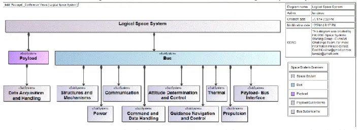
In a similar manner, Figure 2, below, shows the structure of a Logical Space System Model.
Figure 2 – Structure of a logical space system model. © 2015 IEEE. Reprinted, with permission, from D. Kaslow, L. Anderson, S. Asundi, B. Ayres, C. Iwata, B. Shiotani & R. Thompson, “Developing a CubeSat Model-Based System Engineering (MBSE) Reference
Model – Interim Status,” 2015 IEEE Aerospace Conference, 2015, pp. 1-16.
Note that this is just part of what needs to be represented – in addition there is the Ground System, the Environment in which the mission takes place, the project planning and
development phases including V&V. It should be apparent that a space systems engineering ontology must encompass a wide range of considerations, and its development will take time and effort. At JPL this is occurring as the Europa Clipper pre-project extends its modeling to include information from additional engineering disciplines (e.g., trajectory, thermal control). Similarly, the INCOSE CubeSat effort is following a staged process – the first phase dealt with the logical and physical architecture of a reference model and its application to a specific
CubeSat; the second phase introduced behaviors; the third phase improved upon the behavioral aspects of the second phase, and also began development of a generic model. At the time of writing of [Kaslow et al., 2015] the fourth phase was underway to model system development, and expansion of the model scope to all lifecycle stages (including V&V) and all phases of operation (including degraded as well as normal).
As an ontology is extended, some modifications merely require adding a property to an existing object (e.g., adding the property “Requires inspection?” to a component or to a status object that references the component). These will have few ripple effects on the remainder of the ontology and the infrastructure built around it. Conversely, some modifications will have more far-reaching ramifications. Consider a reliability factor that needs the number of Operating hours on a piece of Flight hardware. This requires connection of Operating hours to
components of type Flight hardware. The Components are in turn related to Test (V&V) objects that capture (via a new property) the Number of Hours Operated. This simple example
illustrates that the introduction of a new quantity (Operating Hours) will require ontology modifications to the part of the ontology defining Component and to the part of the ontology defining V&V concepts (Tests, so that they incur and track Operating Hours). The point is that this will require coordination and agreement among the developers and users of different parts of the ontology. Modifications that are especially cross-cutting in nature, such as integrating the notion of risk, may have even farther reaching implications. If risks were merely items to track in 5x5 matrices, their addition to an ontology would not be difficult. However, NASA’s risk
management practices involve identification of risk scenarios, likelihoods and consequences, and the processes for dealing with risks (accepting, watching, mitigating etc.) Properly accommodating the notion of risk into a space systems engineering ontology will need to be done with care.
2.4 Mission Assurance
The previous subsections provided a brief description of some of the key ideas and notions of MBSE. MBSE’s emergence provides an opportunity for Mission Assurance to move from document-centric approaches, which often hinder the contribution and timely conduct of assurance activities, to objective-based products that are embedded within, and compatible with, the modeling used in an MBSE setting. To realize this improvement, mission assurance products and processes need to be able to fit within this framework. For example, safety and reliability engineers must be closely linked to the development taking place in the MBSE framework, from requirements definition through analysis, to support trade studies and design analyses that assure the required reliability and safety. The MBSE framework may demand that reliability and safety analysis and related products take on a new shape. Overall, this new environment presents an unprecedented opportunity to improve effectiveness of the reliability and safety communities. This subsection summarizes developments within NASA’s OSMA that are conducive to this end.
Contemporaneously with the advent of MBSE, NASA’s OSMA has begun the development and promulgation of a new objectives-based approach to standards. As stated in [Groen et al., 2015] (emphasis added):
“…NASA OSMA has developed an approach…to provide for flexibility … while focusing on a vision that is rooted in technical objectives rather than specifying specific products and processes. This approach uses the development of objectives hierarchies with supporting strategies for implementation. The results promise the potential of improved effectiveness, flexibility, and compatibility with Model Based Systems Engineering (MBSE)…”
The objectives-driven approach starts with a single top-level objective of a successful
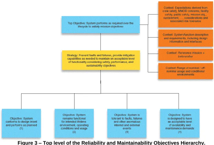
project. This is then broken down into sub-objectives much like the development of any systems engineering hierarchy. Integral to this structure, however, is the use of Strategies to convey information about satisfying objectives. The strategy or strategies that couple with it identify non-process specific methodologies for satisfying the objective. For example, Figure 3 shows the top level of OSMA’s Reliability and Maintainability (R&M) Objectives Hierarchy [NASA OSMA R&M].
11
Figure 3 – Top level of the Reliability and Maintainability Objectives Hierarchy. Reprinted from “Reliability and Maintainability Objectives Hierarchy”
https://sma.nasa.gov/docs/default-source/News-Documents/r-amp-m-hierarchy.pdf?sfvrsn=4 Unlimited distribution of Government document; no re-use statement required. This notation follows the style of the Goal Structuring Notation [Kelly & Weaver, 2004]. As used here, the top-level objective (the topmost blue rectangle) is decomposed into four sub-objectives (the four blue rectangles at the bottom). The strategy for this decomposition is stated in the intermediary yellow box, and the context for all this is stated in the several orange
rectangles to the right. Each objective block is coupled with at least one strategy that is used to facilitate accomplishment of the objective. The four objectives at the bottom of Figure 3 are in turn decomposed into more detailed objectives. The R&M hierarchy was developed by a team that represented a significant cross section of the R&M expertise within NASA. The complete hierarchy is shown at the end of this document in the appendix.
To date OSMA has developed Objectives Hierarchies for the following areas:
Reliability and Maintainability
Software Assurance
ELV Payload
Range Safety
Quality Assurance
For background information and the first four of these, see [NASA OSMA, 2014]. It may be that ultimately there will be a single integrated hierarchy for all of the OSMA disciplines.
The fundamental tenet of the objectives-driven approach is to define the technical objectives and strategies that constitute the assurance considerations for a system, as derived from a top-level objective. This decomposition is intended to help OSMA practitioners focus on the “what” they are trying to achieve without having the “how” dictated. It is an integral part of OSMA’s shift towards use of a Risk Informed Safety Case (RISC) as the means by which to convey the argument for why a system is adequately safe [Dezfuli et al., 2014]. This shift applies to systems
whether engineered by traditional means, or by using MBSE techniques. As emphasized in the quote earlier, its flexibility permits compatibility with, and utilization of, MBSE.
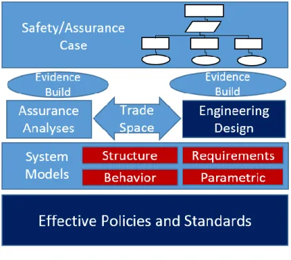
This is notionally indicated in Figure 4, to the right, where layers from bottom to top are as follows:
The bottom layer, “Effective Policies and Standards,” is based on Objective
Hierarchies.
The layer above indicates that for systems that employ MBSE, much of their information is captured in models. For SysML in particular, models are conveyed through diagrams that fall into one or more of the areas shown in red, the four “pillars” of SysML (from the names “Structure”, “Requirements” and “Behavior” it is obvious the areas they cover; in SysML, “Parametrics” “represents constraints on system property values such as performance, reliability, and mass properties, and serves as a means to integrate the
specification and design models with engineering analysis models” [SysML].
A system’s MBSE models are used to inform the activities of Engineering Design and Assurance Analyses. Many of those activities will explore options in a trade space of design alternatives. Selections among these alternatives will be informed by the results of analyses performed on the designs (e.g., various forms of reliability analysis).
As development takes place, evidence is accumulated from the design process (e.g., analyses, tests, inspections, and relevant historical data).
In the vision espoused in [Dezfuli et al., 2014] this evidence is organized into the form of a Risk Informed Safety Case (RISC), or more generally, a Risk Informed Safety and Mission Success Case to cover both safety and mission success criteria. The system-independent Objective Hierarchies that informed the policies and standards can be used as templates to guide the development of the system-specific RISC – for an illustration, see [Witulski et al., 2016].
Figure 4 – Standards, models, engineering activities and safety/assurance cases. © 2016 IEEE. Reprinted, with permission, from J. Evans, S. Cornford & M.S. Feather, “Model based mission assurance: NASA’s
assurance future,” 2016 Annual Reliability and Maintainability Symposium (RAMS), 2016, pp. 1-7.
13
3
MBSE’s implications for MBMA
To understand MBSE’s implications for Mission Assurance, the future of which we’re calling MBMA, a survey of MBSE literature addressing space mission engineering concerns was conducted. The objective was to find how MBSE approaches are being (or could be) applied to support assurance needs. The detailed survey results are in the following section, are organized into seven areas. This section gives a summary of those seven areas, and to give them context, relates them to OSMA’s R&M Objectives Hierarchy.
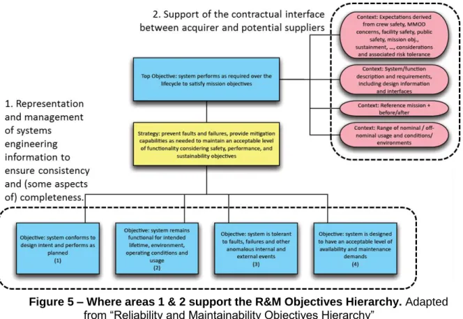
1. Representation and management of systems engineering information. Rigorous model-based representation (i.e., with a semantic underpinning that ensures a shared,
unambiguous understanding) of systems engineering information is the hallmark of MBSE. This rigorous foundation helps ensure consistency and some aspects of completeness of the systems engineering information. The desirable qualities have obvious relevance and benefit to the entire R&M Objectives Hierarchy to the extent that MBSE is carried through the mission lifecycle. May provide specific benefit in 1.B.1.A (Test, inspect, and
demonstrate to an acceptable level to ensure that issues are found) through heading off subtle and hard to detect problems that stem from misinterpretations prevalent when less rigorous documentation is the norm.
2. Support of the contractual interface between acquirer and potential suppliers. One purpose of using NASA’s Objectives Hierarchies is for it to be the means for a developer or service provider to communicate assurance information to NASA. In the R&M Objectives Hierarchy the conveyance of much of this information from acquirer to provider is indicated in the four context descriptions accompanying the top objective of the R&M hierarchy.
These first two areas related to the R&M Objectives Hierarchy as shown in the Figure 5, below.
Figure 5 – Where areas 1 & 2 support the R&M Objectives Hierarchy. Adapted from “Reliability and Maintainability Objectives Hierarchy”
https://sma.nasa.gov/docs/default-source/News-Documents/r-amp-m-hierarchy.pdf?sfvrsn=4 Unlimited distribution of Government document; no re-use
3. Generation of review documentation from the shared MBSE system model. Preliminary results from ongoing NASA applications show evidence of benefits to R&M Hierarchy 1.A.1.A (Demonstrate to an acceptable level that the functionality of the system meets the design intent). Traditional review materials (text and tabular documents) are being
generated from the system models rather than hand-composed, ensuring those materials reflect the consistency of MBSE’s “single authoritative source of truth.” This has potential to benefit reviews and evaluations between acquirer and provider at any Key Decision Point (KDP) provided MBSE covers that stage in the system’s lifecycle. Figure 6, below, thus suggests the universal scope of this with respect to the R&M Objectives Hierarchy.
Figure 6 – Where area 3 supports the R&M Objectives Hierarchy. Adapted from “Reliability and Maintainability Objectives Hierarchy” https://sma.nasa.gov/docs/default-source/News-Documents/r-amp-m-hierarchy.pdf?sfvrsn=4 Unlimited distribution of Government
document; no re-use statement required.
4. Automated assistance for generating reliability artifacts (FMECAs, Fault Trees, etc.).
Relevant to sub-objectives 2 (System remains functional for intended lifetime, environment, operating conditions and usage), 3 (System is tolerant to faults, failures and other
anomalous internal and external events), and to a lesser extent so far, 4 (System is
designed to have an acceptable level of availability and maintenance demands). Generally, applications to date have been during design. It remains to be seen how MBSE will affect the later phases of development, most especially operations.
5. Representation of and reasoning about off-nominal states and behaviors. This is a
fundamental capability supporting the previous area (reliability artifacts), therefore likewise relevant to sub-objectives 2, 3 and 4. Several efforts have focused on developing
automated assistance, using its needs to drive the initial development of the representation.
15
Figure 7 – Where areas 4 & 5 support the R&M Objectives Hierarchy. Adapted from “Reliability and Maintainability Objectives Hierarchy” https://sma.nasa.gov/docs/default-source/News-Documents/r-amp-m-hierarchy.pdf?sfvrsn=4 Unlimited distribution of Government
document; no re-use statement required.
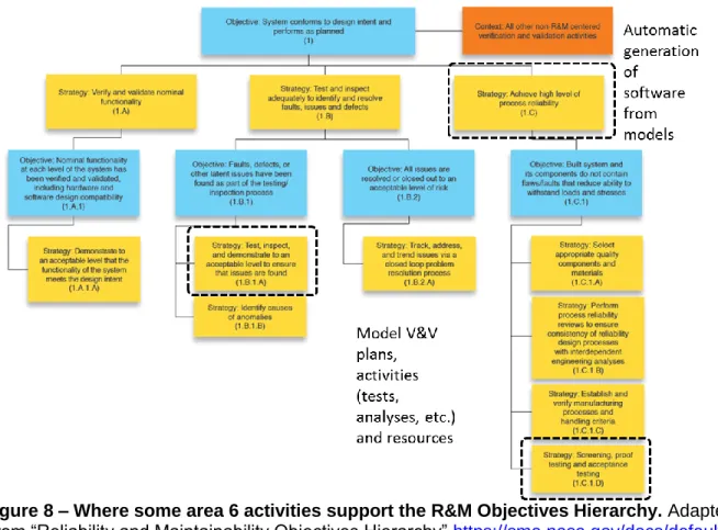
6. Support for activities post-design. While most of the MBSE literature focuses on the design stage, some address later activities, notably testing. Planning for and managing the testing activities could potentially benefit from the same MBSE principles of capturing the pertinent information in a formal representation, relevant to: 1.B.1.A, 2.A.1.D (Perform qualification testing and life demonstration to verify design for intended use), 2.B.1.D (Plan and perform life testing), 4.A.1.G (Provide demonstration testing to verify ‘detect, diagnose, isolate’ capability of systems and confirm corrective and preventive maintenance task actions and analysis) and 1.C.1.D (Screening, proof testing and acceptance testing). In the software arena there are instances of software being automatically generated from models, thus contributing to 1.C (Achieve high level of process reliability), and of software being
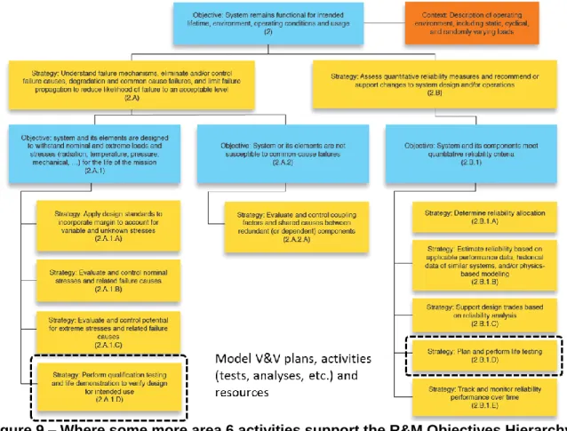
extensively tested against computer simulations of the system and its operating conditions. Figure 8, next page, shows these specific R&M Objective areas in the hierarchy for sub-objective 1, and Figure 9, page after, for the hierarchy for sub-sub-objective 2.
Figure 8 – Where some area 6 activities support the R&M Objectives Hierarchy. Adapted from “Reliability and Maintainability Objectives Hierarchy” https://sma.nasa.gov/docs/default-source/News-Documents/r-amp-m-hierarchy.pdf?sfvrsn=4 Unlimited distribution of Government
17
Figure 9 – Where some more area 6 activities support the R&M Objectives Hierarchy. Adapted from “Reliability and Maintainability Objectives Hierarchy”
https://sma.nasa.gov/docs/default-source/News-Documents/r-amp-m-hierarchy.pdf?sfvrsn=4 Unlimited distribution of Government document; no re-use statement required. 7. Correctness of the MBSE models themselves. Since the system design information is captured in models, it is crucial that they be correct, with obvious relevance all the previous six areas and where they relate to the R&M Objectives Hierarchy.
4 MBMA details found in the MBSE literature
This section presents the detailed results of our survey of the MBSE literature as it pertains to space mission engineering concerns, in particular how MBSE approaches are being (or could be) applied to support mission assurance needs. These results are organized into the seven areas introduced in the previous section, namely:
1. Representation and management of systems engineering information
2. Support of the contractual interface between acquirer and potential suppliers 3. Generation of review documentation from the shared MBSE system model
4. Automated assistance for generating reliability artifacts (FMECAs, Fault Trees, etc.). 5. Representation of and reasoning about off-nominal states and behaviors.
6. Support for activities post-design.
7. Correctness of the MBSE models themselves.
4.1 Representation and management of systems engineering information
In general, many papers and presentations argue for the benefit of model-centric rather than document-centric design; the following examples report application to space systems.Integration of flight software developed for the James Webb Space Telescope’s Integrated Science Instrument Module is briefly reported in [Aguilar, 2012]. The C&DH Core Flight
Software (FSW) development was done at GSFC and the Science Instrument FSW applications were developed by different teams at several disparate locations. A Rational Rose Structure Diagram was used to unambiguously indicate the core system’s communication ports to other subsystem components and to its own internal “capsules”.
Use of MBSE to manage development of the ground system for control of the OSIRIS-Rex spacecraft during its encounter with asteroid Bennu is described in [Wibben & Furfaro, 2015]. Three areas are listed as benefiting from MBSE: representation and flow down of the
requirements on the ground system, representation of its architecture (leading to development of the formal documentation of that architecture in the form of Interface Control Documents and Operational Interface Agreements), and capture of testing and V&V plans. In addition to
diagramming static views of the architecture, FFBDs (Functional Flow Block Diagrams) are used to support discrete-event simulation of system behaviors to validate the system’s run-time behavior.
Similar benefits are reported in [Karban et al., 2014] in the related area of systems engineering of astronomical telescopes.
Another important benefit of MBSE’s single authoritative source of information is to serve as the intermediary among a federation of special-purpose representations and tools. This is seen, for example, in [Kaslow et al., 2014] where MBSE behavioral modeling of a CubeSat mission is connected to analytic capabilities (MATLAB® and STK®). The use of MBSE to manage the connection of system data with simulation environments is also the subject of [Cencetti, 2014]. Both of these show how the combination of MBSE and simulation can support conducting sensitivity analyses and trade studies of alternative designs. This is useful for the purpose of approaching an optimal design, not merely a good-enough design – an aspect that is called for in the system safety concept of “As Safe As Reasonably Practicable” (ASARP) [Dezfuli et al., 2014], or, for purely robotic missions once they have left Earth, As Successful As Reasonably Practicable.
4.2 Support of the contractual interface
A report on “research practices pertaining to methods, tools, and techniques proposed to facilitate the use of MBSE across the contractual interface in a competitive tender environment” is given in [Do et al., 2014]. The authors assert that MBSE has long been successfully applied
19
across contractual boundaries in settings where “mutual trust is well developed and mutual goals are well understood.” Their paper addresses the situation of a competitive environment, where a supplier would wish to excise proprietary information from the model they submit as part of the bid, and the acquirer would wish to excise certain sensitive information (e.g., costing, management) from the model they put forth to elicit bids. The paper lists details on these topics resulting from “workshops with key stakeholders.” They go on to mention that the acquirer’s model served as a good starting point for the supplier to elaborate further into a more detailed model.
4.3 Generation of review documentation
“Document/Expert – Centric Acquisition” is contrasted with “Data-Driven/MBSE Acquisition” in [Montgomery, 2014], which suggests many of the analysis results needed for acquisition decisions can be machine-generated from models, replacing labor intensive human
assessments by teams of experts.
Textual forms of the acquirer’s Operational Concept Document, Function and Performance Specification and Test Concept Document are described as being generated from a reference model in [Do et al., 2014]. It also goes on to say that some members of the supplier team worked directly from the model, and those that initially preferred to work from the generated textual forms increasingly switched to the model.
A pilot study on a “moderate size flight project” – MISSE-X, a payload for hosting
experiments, to be installed on the exterior of the ISS is reported in [Vipavetz et al., 2012]. The report discussed the pros and cons of MBSE in preparation for the project’s System
Requirements Review. They used:
SysML to “document the system concept of operations as well as some assembly, integration and test activities” (use-case diagrams for stakeholder interactions, activity diagrams to document system functions, activity diagrams, state-machine diagrams and sequence diagrams to document intended behavior, package diagram of system
architecture and external boundaries, IBD for flows and interfaces between systems) and
Vitech’s CORE™ to manage the requirements (traceability through levels of requirements, allocations, owners and verification methods).
They report benefits of consistency, ease of access to complete, current information, and clarity across the team. The review need was to demonstrate existence of a feasible and satisfactory system design (feasible = could be implemented consistent with cost, schedule & risk; satisfactory = design meets project goals). Exports from CORE were used to provide information to team members without requiring them to be CORE users, and to generate complete documents directly from CORE. Review materials were developed from the SysML and CORE models. However, their paper identifies several challenges:
“no guarantee that the model is correct” – note that they did not pursue extensively execution of models, stating “developing executable models within the model itself was found to be challenging”
Restarts in creating the meta-model (ontology)
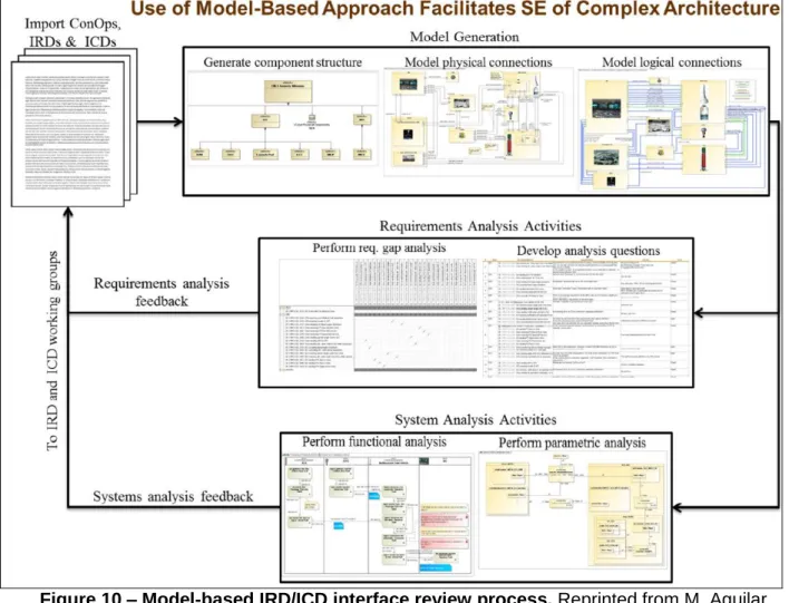
Default presentation options from SysML tool often needed extensive re-working. Modeling followed by document generation was used to generate the contents of an assessment report of NASA Ground Systems Development and Operations’ (GSDO) plan to verify their command and control software [Aguilar et al., 2014]. The modeling focused on physical and logical interfaces, and its role in the assessment is indicated by Figure 10, below.
Figure 10 – Model-based IRD/ICD interface review process. Reprinted from M. Aguilar, K. Bonanne, J.A. Favretto, M.M. Jackson, S.L. Jones, R.M. Mackey, M.A. Sarrel & K.A. Simpson, Review of Ground Systems Development and Operations (GSDO) Tools for Verifying
Command and Control Software, NASA/TM-2014-218278, June 2014, with permission of the authors.
The information available to the review team allowed them to perform requirements gap analysis (looking for missing and inconsistent requirements), and a limited amount of functional analysis. The document further states that “All text, tables, and illustrations in the GAILA [GSDO Avionics Integration Laboratories Assessment] report were extracted and formatted from the SysML model repository.”
4.4 Generation of reliability artifacts
There are numerous examples of MBSE being used to provide automated assistance to generate reliability artifacts (FMECAs, Fault Trees, etc.).
Generation of FMEAs from SysML information, specifically from Sequence Diagrams (SDs) and Internal Block Diagrams (IBDs), is described in [David et al., 2009] & [Cressent et al., 2011] (see also the next section for further papers by the same set of authors). They assume a
database (referred to in the paper as a “Dysfunctional Behavior Database”) of components and their failure properties – their failure modes, and (optionally) additional information such as failure rate. They further allow for the following:
A Parametric Diagram (PD) expressing the computation of functional attributes degradation during the failure mode occurrence.
21
A PD indicating the computation of the failure rate of each failure mode. (This constraint depends on the environmental and structural parameters)
A Statechart Diagram describing the dynamic behavior of the component in the failure mode state.
They stress that in IBDs they utilize two kinds of ports – standard ports and flow ports. Standard ports are suited for representing control and command requests (including exchange of information); flow ports are suited to representation of data, material or energy flowing through the connectors to/from such ports.
Scalable, automated generation of a FMEA, illustrated on a model of a satellite, its ground control system, and ground users is concisely reported in [Hecht et al., 2014]. They assume a SysML model with BDDs, IBDs (in which failure propagation paths are represented), state transition machines (including both normal and failed states) and activity diagrams (that generate the triggers driving state transitions). From these they also automatically generate a model to input into AltaRica (“a tool and language implementing mode automata”) to model fault propagation.
Collaborations between Johnson Space Center and Tietronix Software Inc. are reported in [Wang et al., 2015] & [Sargusingh et al., 2015]. Generation of a FMECA and a Fault Tree from a SysML model is illustrated in [Wang et al., 2015]. They too assume that SysML IBD has the details of the system architecture and that the state transition diagrams include nominal and off-nominal (failed) states, using state machine events and guards to encode propagation of failure effects from one component to another. The example they use as illustration is a “Common Cabin Air Assembly” to provide life-critical air circulation in the ISS, and they show how the generated FMECA takes into account the fault-tolerance provided by redundancy in the modeled system. It does not appear that they deal with continuous physical flows in the same manner [David et al., 2009]. Application to design of a water recycling system (the “Cascade Distillation System”) intended for use in the context of a human mission to Mars (for which high reliability and low mass are both driving concerns that make the design a challenge) is reported in [Sargusingh et al., 2015]. The paper shows the results of their tooling to (a) “extract the FMECA from the … FSMs (Finite State Machines) defining the possible failed states” and (b) “traverse behavior diagrams to extract the fault event paths for analysis”, combining these into a fault tree.
An approach to automatic generation of FMEA and Fault Tree Analysis (FTA) artifacts from system models is outlined in [Mhenni et al., 2014a] & [Mhenni et al., 2014b]. Their FMEA generation process starts from a top-level functional breakdown for the system, and yields a list of generic failure modes for those functions and potential causes and effects. At this stage additional failure modes can be added manually. Having allocated components to functions, the generation of a component FMEA proceeds in a similar manner. Their Fault Tree generation process utilizes the FMEAs, and hinges on graph-traversals of SysML Internal Block Diagrams (IBDs) that express component interactions and the internal structure (connectivity) of the system. They show how they convert patterns inside an IBD representing redundancy or feedback loops into the corresponding fault tree structures using AND and OR gates as appropriate. They use as illustration an electromechanical actuator used to actuate ailerons – this is described as a case study, but not an actual industrial application.
4.5 Off-nominal states and behaviors
Off-nominal behavior, of particular interest to the OSMA practitioners, has begun to be explored in the context of MBSE. Open questions remain regarding the integration of risk into the models and a methodology for managing/reducing these risks.
Verification of fault management behavior by execution of a model of NASA’s Ares & Orion communication during abort is briefly reported in [Aguilar, 2013]. This provides an illustration of
a missing transition guard, presumably discovered in a simulation that exhibited an unwanted launch delay. Other examples of errors “found through modeling” are also listed.
A small manually conducted feasibility study, of representing failures so as to check for safety and security properties such as “robust to any single failure”, “robust to erroneous data”, “resilient to fake GPS signal” is reported in [Brunel et al., 2014]. They indicate the potential for translation into Alloy, a language and toolset for formal analysis of consistency.
The need to integrate the representation of, and reasoning about, off-nominal behavior with the standard system engineering process is addressed in [Cressent et al., 2013]. They describe typical reliability activities (e.g., FMEA) and their data sources & sinks. They stress the need to model the dynamics of off-nominal behaviors, presenting a meta-model (ontology extensions) appropriate to this, including treatment of off-nominal behaviors at multiple levels of abstraction (boolean to represent working or not; qualitative to include representation of “degraded”
conditions; formulae for quantitative calculations e.g., using failure rate values).
Semi-automated mapping from SysML into AADL for purposes of analyzing real-time computational aspects of the system is detailed in [Cressent et al., 2010] (the AADL language and associated tools provide another model-based approach to representation and reasoning for real-time software systems development; see also [Fernández, 2014] for AADL and MBSE).
Figure 11, next page, from [Cressent et al., 2013], shows the role of various forms of analyses and the data they ingest/produce. In that paper it is captioned as “Fig. 1. A project lifecycle process example. Req & Cons, Requirements and Constraints; PHA, Preliminary Hazard Analysis; FMEA, Failure Mode and Effects Analysis; FFMEA, Functional Failure Mode and Effects Analysis (FMEA based on the functions of the system instead of the components of the system).”
23
Figure 11 – Various analyses and the data they ingest. Reprinted from Reliability Engineering and System Safety, 111, R. Cressent, P. David, V. Idasiak & F. Kratz, “Designing
the database for a reliability aware Model-Based System Engineering process,” 171-182, copyright 2013, with permission from Elsevier.
A “safety profile” – stereotypes to extend SysML in order to represent information relevant to failures etc. (“safety profile” could equivalently be called meta-model or ontology) is presented in [Mhenni et al., 2014a]. They offer a case study using it to represent failure information for an electromechanical actuator – specifically, an actuator of the ailerons in an aircraft. They also describe semi-automatic generation of FMEAs from this information – see the “Automated assistance for generating reliability artifacts” subsection for further discussion of this.
Some details of their approach to representing off-nominal information are seen in Figure 12 and Figure 13, next page.
Figure 12 – Class diagram for FMEA artifacts. © IEEE. Reprinted, with permission, from F. Mhenni, J-Y. Choley & N. Nguyen, “SysML Safety Profile for Mechatronics,” in Mecatronics (MECATRONICS), 2014 10th France-Japan / 8th Europe-Asia Congress on, 2014, pp. 29-34.
Figure 13 – Safety profile diagram. © IEEE. Reprinted, with permission, from F. Mhenni, J-Y. Choley & N. Nguyen, “SysML Safety Profile for Mechatronics,” in Mecatronics (MECATRONICS), 2014 10th France-Japan / 8th Europe-Asia Congress on, 2014, pp. 29-34.
25
A similar approach is followed in [Biggs et al., 2016], presenting a SysML profile (appropriately named “SafeML”) specifically for representing safety-related concerns of a system. Profiles are given for representing hazardous events and for defenses to them. The paper also shows the use of alternative model views, generated automatically from the model by a plug-in to the tool being used to support SysML. For example, a matrix view relating harm contexts to the defenses against those harms is used to provide a convenient overview from which it is easy to see which, if any, harm contexts lack defenses. Figure 14, below, shows this paper’s SafeML profile to represent hazardous events; see the paper for a similar figure
showing the profile for elements related to defenses.
Figure 14 – Profile elements relating to hazardous events. Springer Journal of Software and Systems Modeling, “A profile and tool for modelling safety information with design information in SysML,” 15(1), 2016, 147-178, G. Biggs, T. Sakamoto & T. Kotoku, © 2016. With permission of
Springer.
Note that in terms of what’s included, this is similar to the safety profile from [Mhenni et al., 2014a] presented earlier – both approaches to profiles provide attributes of Severity and Probability, for example, but do so in different ways.
4.6 Support for activities post-design
The majority of reports of MBSE applications (and hence the majority of the attention) has so far been focused on systems in their early phases. Nevertheless, several papers take the approach of looking ahead to how MBSE might assist those later lifecycle phases. In particular, using MBSE to model V&V activities is a common theme.
The argument for a model of system information that spans the entire lifecycle, all the way from design choices, through development and V&V, to operation, appeared in [Cornford et al., 2006]. The main elements of this model are requirements, functions, components, risks, work