http://dspace.nitrkl.ac.in/dspace
Multiple Mobile Robots
A
Thesis
Submitted
to
the
Department
of
Mechanical
Engineering
of
National
Institute
of
Technology,
Rourkela
in
partial
fulfillment
of
the
requirements
for
the
degree
of
DOCTOR
OF
PHILOSOPHY
IN
ENGINEERING
By
Saroj
Kumar
Pradhan
Department
of
Mechanical
Engineering
National
Institute
of
Technology
Rourkela
‐
769008
(India)
Multiple Mobile Robots
A
Thesis
Submitted
to
the
Department
of
Mechanical
Engineering
of
National
Institute
of
Technology,
Rourkela
in
partial
fulfillment
of
the
requirements
for
the
degree
of
DOCTOR
OF
PHILOSOPHY
IN
ENGINEERING
By
Saroj
Kumar
Pradhan
Under
the
Guidance
of
Dr.
D.
R.
Parhi
Dr.
A.
K.
Panda
(Supervisor)
(Co
‐
supervisor)
Department
of
Mechanical
Engineering
National
Institute
of
Technology
Rourkela
‐
769008
(India)
This Thesis is Dedicated
to
my Late Mother Smt. Basanti Pradhan
and
Declaration
I hereby declare that the work which is being presented in the thesis entitled “Navigation Techniques for Control of Multiple Mobile Robots” in partial fulfillment of the requirements for the award of the degree of DOCTOR
OF PHILOSOPHY submitted to the Department of Mechanical Engineering of
National Institute of Technology, Rourkela, is an authentic record of my own work under the supervision of Dr. D. R. Parhi, Department of Mechanical Engineering and Dr. A. K. Panda, Department of Electrical Engineering. I have not submitted the matter embodied in this thesis for the award of any other degree or diploma of the university or any other institute.
Date: 28th May, 2007 Saroj Kumar Pradhan
Certificate
This is to certify that the thesis entitled “Navigation Techniques for Control of Multiple Mobile Robots” being submitted by Shri Saroj Kumar Pradhan is a bona fide research carried out by him at Mechanical Engineering Department, National Institute of Technology, Rourkela, under our guidance and supervision. The work incorporated in this thesis has not been, to the best of our knowledge, submitted to any other University or any Institute for the award of any degree or diploma.
D. R. Parhi A. K. Panda (Supervisor) (Co‐Supervisor) Date: 28th May, 2007
Acknowledgements
It has been a pleasure for me to work on this dissertation. I hope the reader will
find it not only interesting and useful, but also comfortable to read.
The research reported here has been carried out in the Mechanical Engineering
Department of National Institute of Technology, Rourkela at the Robotics Laboratory. I
am greatly indebted to many persons for helping me to complete this dissertation.
First and foremost, I wish to express my sense of gratitude and indebtedness to
my supervisors, Dr. D.R. Parhi and Dr. A.K. Panda for their inspiring guidance,
encouragement, and untiring efforts throughout the course of this work. Their timely
help, constructive criticism, and painstaking efforts made it possible to present the work
contained in this thesis.
I express my heartfelt thanks to the reviewers for giving their valuable comments
on the published papers in different international journals, which helps to carry the
research works in a right direction. I also thank to the international and national
conference organisers for intensely reviewing the published papers.
I am grateful to Prof. S.K. Sarangi, Director, and Head of the Department,
Mechanical Engineering, for their active interest and support. I am also thankful to the
staff members of Mechanical Engineering Department, National Institute of Technology,
Rourkela for providing all kind of possible help throughout the research work. I am also
thankful to the head and staff members at my workplace for their valuable supports
during the research.
I express my deep sense of gratitude and reverence to my beloved father Sri
Narendra Pradhan, mother Late Smt. Basanti Pradhan, sisters and my brother Late Sri
Manoj Kumar Pradhan for their blessings, forbearance and endeavors to keep my moral
high throughout the period of my work. I am grateful to my wife Saswati Soumya
Pradhan, for her support and patience during this work, and to my daughter
Manishikha, for constantly reminding me with less patience but no less love, that there
is life outside the office.
Thanks are due to Dr. Rabindra Kumar Behera, faculty Mechanical Engineering
Department, for his constant advice and encouragement through out the research
work. It is a great pleasure for me to acknowledge and express my appreciation to all my
well wishers for their understanding, relentless supports, and encouragement during
my research work. Last but not the least; I wish to express my sincere thanks to all those
who directly or indirectly helped me at various stages of this work.
Synopsis
The investigation reported in this thesis attempt to develop efficient techniques for the control of multiple mobile robots in an unknown environment. Mobile robots are key components in industrial automation, service provision, and unmanned space exploration. This thesis addresses eight different techniques for the navigation of multiple mobile robots. These are fuzzy logic, neural network, neuro‐fuzzy, rule‐base, rule‐based‐neuro‐fuzzy, potential field, potential‐field‐ neuro‐fuzzy, and simulated‐annealing‐ potential‐field‐ neuro‐fuzzy techniques.
The main components of this thesis comprises of eight chapters. Following the literature survey in Chapter‐2, Chapter‐3 describes how to calculate the heading angle for the mobile robots in terms of left wheel velocity and right wheel velocity of the robot.
In Chapter‐4 a fuzzy logic technique has been analysed. The fuzzy logic technique uses different membership functions for navigation of the multiple mobile robots, which can perform obstacles avoidance and target seeking.
Chapter‐5 consists of two subsections. In first subsection the neural network technique has been developed and analysed for controlling the multiple mobile robots. Then this technique is hybridised with fuzzy logic to improve the
fuzzy logic controller of Chapter‐4 with the addition of a neural network as a pre‐processor for the fuzzy controller.
Chapter‐6 analyses a rule‐based‐neuro‐fuzzy technique for controlling the mobile robots. A rule‐base technique is first developed and then it is combined with the neuro‐fuzzy technique of Chapter‐5 to increase its efficiency.
Chapter‐7 deals with an efficient potential field method for navigation of multiple mobile robots. Then a hybrid potential‐field‐neuro‐fuzzy technique for controlling the mobile robots is described.
Finally, Chapter‐8 analyses the optimisation of potential field with the help of simulated annealing for escaping local minima. The developed potential‐ field‐simulated‐annealing‐neuro‐fuzzy technique is described in simulation as well as for real mobile robots.
Table of Contents
1 Introduction ... 1
1.1 Background... 1
1.2 Aims and Objectives of this Research ... 3
1.3 Outline of the Thesis... 4
2 Literature Review... 6
2.1 Introduction ... 6
2.2 Mobile Robot Navigation... 6
2.3 Kinematic Analysis of Mobile Robots... 10
2.3.1 Introduction ... 10
2.3.2 Kinematic Analysis for Mobile Robot Navigation ... 10
2.4 Fuzzy Logic Technique ... 11
2.4.1 Introduction ... 11
2.4.2 Fuzzy Logic Technique for Mobile Robot Navigation ... 11
2.5 Neural Network Technique... 20
2.5.1 Introduction ... 20
2.5.2 Neural Network Technique for Mobile Robot Navigation... 24
2.5.3 Neuro‐Fuzzy Technique for Mobile Robot Navigation ... 28
2.6 Rule Based Technique ... 34
2.6.1 Introduction ... 34
2.6.2 Rule based Technique for Mobile Robot Navigation... 35
2.7 Potential Field Navigation Technique ... 37
2.7.1 Introduction ... 37
2.7.2 Potential Field Technique for Mobile Robot Navigation ... 37
2.8 Simulated Annealing Technique ... 42
2.8.1 Introduction ... 42
2.8.2 Simulated Annealing Technique ... 42
2.9 Sensors for Mobile Robots ... 43
2.9.1 Ultrasonic Sensors for Robot Navigation ... 44
2.9.2 Infrared Sensors for Robot Navigation... 46
2.9.3 Other Sensors Used in Navigation ... 47
2.10 Summary ... 48
3 Kinematic Analysis of Mobile Robots... 49
3.1 Introduction ... 49
3.2 Configuration of Mobile Robot ... 49
3.3 Kinematic Model ... 51
4 Fuzzy Logic Technique ... 55
4.1 Introduction ... 55
4.2 Control Architecture... 56
4.2.1 Analysis of Obstacle Avoidance and Target Seeking Behaviour... 56
4.2.2 Fuzzy Mechanism for Mobile Robot Navigation ... 61
4.2.3 Obstacle Avoidance ... 62
4.2.4 Control Steering Action for Target ... 63
4.2.5 Petri Net Modelling to avoid Collision among the Robots... 70
4.3 Demonstrations ... 72
4.3.1 Obstacle Avoidance and Target Seeking by Multiple Mobile Robots 72 4.3.2 Collision Free Movements in a Cluttered Environment ... 74
4.3.3 Obstacle Avoidance by a Large Number of Robots... 75
4.3.4 Escape from Dead Ends ... 75
4.4 Comparison between the Different Types of Fuzzy Controller... 78
4.4.1 Simulation Results ... 78
4.4.2 Experimental Results... 82
4.5 Summary ... 86
5 Neural Network Technique ... 87
5.1 Introduction ... 87
5.1.1 Multilayer Neural Network Based Navigation Technique... 88
5.2 Neuro‐Fuzzy Technique ... 93
5.2.1 Obstacle Avoidance ... 95
5.2.2 Target Finding ... 95
5.3 Demonstrations ... 96
5.3.1 Neural Network Technique... 96
5.3.1.1 Obstacle Avoidance and Target Seeking ... 96
5.3.1.2 Escape from Dead Ends ... 98
5.3.1.4 Inter Robot Collision Avoidance ... 98
5.3.2 Neuro‐Fuzzy Technique ... 102
5.3.2.1 Collision Free Movements in a Cluttered Environment ... 102
5.3.2.2 Escape from Dead Ends ... 102
5.3.2.3 Obstacle Avoidance by a Large Number of Robots... 102
5.4 Comparisons... 106
5.4.1 Comparison between the Different Types of Fuzzy Controllers and Neuro‐Fuzzy Controller... 106
5.4.2 Comparison of the Developed Neuro‐Fuzzy Technique with Marichal and Janglova Techniques ... 111
5.5 Summary ... 119
6 Rule Based Technique ... 120
6.1 Introduction ... 120
6.2 Rule Based Technique for Mobile Robots... 122
6.2.1 Analysis of Rule‐Based Technique ... 126
6.3 Rule‐Based ‐ Neuro‐Fuzzy technique ... 131
6.4 Demonstrations ... 133
6.4.1 Rule‐Based Technique ... 133
6.4.1.1 Obstacle Avoidance and Target Seeking by Multiple Mobile Robots…………. ... 133
6.4.1.2 Obstacle Avoidance by a Large Number of Robots... 133
6.4.1.3 Escape from Dead Ends ... 136
6.4.1.4 Collision Free Movements in a Cluttered Environment ... 136
6.4.2 Rule‐Based‐Neuro‐Fuzzy Technique ... 139
6.4.2.1 Escape from Dead Ends ... 139
6.4.2.2 Navigation by Nine Hundred Ninety Mobile Robots ... 139
6.4.2.3 Inter Robot Collision Avoidance ... 139
6.4.2.4 Experimental Validation with the Simulation Results for Two Mobile Robots... 143
6.5 Comparison between Different Controllers... 145
6.5.1 Experiments with Single Real Mobile Robot ... 148
7 Potential Field Navigation Technique... 152
7.1 Introduction ... 152
7.2 Analysis of Potential Field Navigation technique... 153
7.2.1 Attractive Potential Function ... 153
7.2.2 Repulsive Potential Function ... 154
7.2.3 New Repulsive Potential Function... 158
7.2.4 Robot Navigation ... 161
7.2.5 Hybrid Potential Field Navigation technique... 166
7.3 Demonstrations ... 168
7.3.1 Potential Field Navigation Technique ... 168
7.3.1.1 Obstacle Avoidance and Target Seeking by Multiple Mobile Robots ………..168
7.3.2 Potential‐Field‐Neuro‐Fuzzy Technique ... 169
7.3.2.1 Escape from Dead Ends ... 169
7.3.2.2 Navigation of Several Mobile Robots ... 171
7.3.2.3 Inter Robot Collision Avoidance ... 171
7.3.2.4 Experimental Validation for Two Mobile Robots with the Simulation Results ... 174
7.4 Comparison between Different Controllers... 176
7.4.1 Simulation Results ... 176
7.4.1.1 Experiments with single Mobile Robot... 180
7.4.1.2 Experiments with Two Real Mobile Robots... 182
7.5 Summary ... 184
8 Simulated Annealing ... 185
8.1 Introduction ... 185
8.2 Simulated Annealing ... 186
8.2.1 Simulated Annealing Technique ... 187
8.2.2 Hybrid Technique ... 193
8.3 Demonstrations ... 195
8.3.1 Inter Robot Collision Avoidance ... 195
8.3.2 Experimental Validation for Two Mobile Robots with the Simulation Results... 196
8.3.4 Navigation of Several Mobile Robots ... 200
8.4 Comparison between Different Controllers... 202
8.4.1 Simulation Results ... 202
8.4.2 Experiments with Single Real Mobile Robot ... 206
8.4.3 Experiments with Multiple Mobile Robots ... 208
8.5 Summary ... 215
9 Conclusions and Further Work ... 216
9.1 Contributions... 216
9.2 Conclusions... 217
9.3 Further Work ... 217
Appendix – A ... 219
Software used for Robot navigation... 219
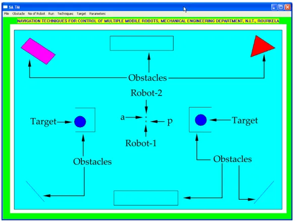
A.1 Navigation Software... 219
A.1.1 Obstacle Menu:... 219
A.1.2 Number of Robot Menu: ... 219
A.1.3 Run Menu:... 219
A.1.4 Techniques Menu:... 219
A.1.5 Target Menu:... 221
A.1.6 Manual Command (Parameter Menu):... 221
Appendix – B... 223
Petri Net Model ... 223
B.1 Basic Definitions of Petri Net Model:... 223
Appendix ‐ C ... 230
Description of Experimental Mobile Robots... 230
C.1 Khepera II Robot ... 230
C.2 Boe‐Bot Robot ... 231
C.3 Hemisson Robot ... 232
C.4 Koala Robot... 233
Appendix – D ... 234
Data Mining Tools See5 ... 234
D.1.2 Names File... 234 D.1.3 Data File... 235 D.1.3.1 Locate Data... 236 D.1.3.2 Construct Classifier... 236 D.1.3.3 Stop... 236 D.1.3.4 Review Output ... 236 D.1.3.5 Use Classifier ... 236 D.1.3.6 Cross‐Reference ... 236 D.1.4 Constructing Classifiers ... 236 D.1.5 Rulesets... 237 Appendix – E... 240
Data for Rule‐based Controller ... 240
References... 250
Published Papers... 279
Papers Published in International Journals:... 279
List of Tables
Table 4.1. Parameters of fuzzy membership functions... 58
Table 4.2. Obstacle avoidance for three‐membership function... 64
Table 4.3. Obstacle avoidance for five‐membership function... 65
Table 4.4. Target seeking for three‐membership function... 65
Table 4.5. Target seeking for five‐membership function... 65
Table 4.6. Path lengths using different fuzzy controllers... 81
Table 4.7. Time taken to reach the target using different fuzzy controllers... 81
Table 4.8. Time taken by robots in simulation and experiment to reach target (Fuzzy logic technique)... 85
Table 5.1. Rules for obstacle avoidance... 95
Table 5.2. Rules for target finding... 96
Table 5.3. Path lengths using different controllers... 109
Table 5.4. Time taken to reach the target using different controllers... 110
Table 5.5. Performance evaluation of different technique for navigation of one mobile robot... 110
Table 6.1. Path lengths using different rule base techniques... 147
Table 6.2. Time taken to reach the target using different techniques... 148
Table 6.3. Time taken by robots in simulation and experiment to reach the target (Rule‐based technique)... 150
Table 7.1. Path lengths using different techniques... 179
Table 7.2. Time taken to reach the target using different techniques... 179
Table 7.3. Time taken by robots in simulation and experiment to reach target (Potential field navigation technique)... 182
Table 8.1. Path lengths using different techniques... 205
Table 8.2. Time taken to reach the target using different techniques... 205
Table 8.3. Time taken by robots in simulation and experiment to reach target (Simulated annealing)... 206
List of Figures
Figure 2.1. Flow diagram of the horizontal decomposition method for the
navigation of a mobile robot... 8
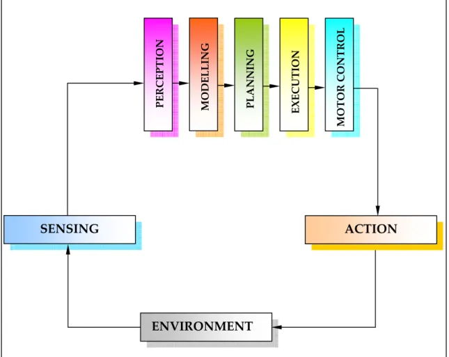
Figure 2.2. Flow diagram of the vertical decomposition method for the navigation of a mobile robot... 9
Figure 2.3. Model of a neuron... 20
Figure 2.4. Three common activation functions... 23
Figure 3.1. A three wheeled mobile robot... 50
Figure 3.2. Wheeled mobile robot with left and right angular velocities... 50
Figure 3.3. Wheeled mobile robot with no slip condition... 51
Figure 3.4. A Robot... 51
Figure 3.5. Kinematic parameters of the wheeled mobile robots... 52
Figure 3.6. Calculation of angular velocity... 54
Figure 4.1. Fuzzy Controllers for Mobile Robot Navigation... 59
Figure 4.2. Fuzzy membership functions... 60
Figure 4.3. Left, Front and Right Obstacles Distances... 66
Figure 4.4. Resultant Left and Right Wheel Velocity... 70
Figure 4.5. Petri Net Model for avoiding inter‐robot collision... 71
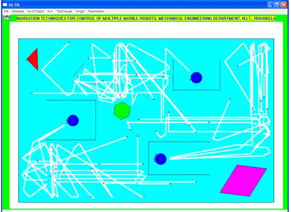
Figure 4.6. Obstacle avoidance and target seeking by forty‐five mobile robots using five‐membership function (Initial position)... 72
Figure 4.7. Obstacle avoidance and target seeking by forty‐five mobile robots using five membership function (Intermediate state)... 73
Figure 4.8. Obstacle avoidance and target seeking by forty‐five mobile robots using five membership function (Final state)... 73
Figure 4.9. Collision free movement using five‐membership FLC (Initial scenario)... 74
Figure 4.10. Collision free movement using five membership FLC (Final state). 75 Figure 4.11. Navigation of large number of robots before starting the mission using five‐membership FLC (1000 robots)... 76
Figure 4.12. Navigation of large number of robots after some time from the starting of the mission using five membership FLC (1000 robots)... 76
Figure 4.13. Environment for escaping from the dead ends before starting of the mission using five‐membership FLC... 77
Figure 4.14. Recorded paths of fifteen robots in case of escaping from U‐shaped
objects and getting the targets using five‐membership FLC... 77
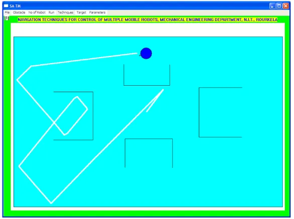
Figure 4.15. Workspace for one mobile robot with one target (initial scenario)... 79
Figure 4.16. Navigation path for one mobile robot using three‐membership fuzzy controller... 79
Figure 4.17. Navigation path for one mobile robot using five membership triangular fuzzy controller... 80
Figure 4.18. Navigation path for one mobile robot using Gaussian membership fuzzy controller... 80
Figure 4.19. Initial scenario for real robot (Khepera II) for the similar simulated environment as shown in Figure 4.15... 82
Figure 4.20. Intermediate scenario ‐ one for real robot (Khepera II) using Gaussian membership fuzzy controller... 82
Figure 4.21. Intermediate scenario ‐ two for real robot (Khepera II) using Gaussian membership fuzzy controller... 83
Figure 4.22. Intermediate scenario ‐ three for real robot (Khepera II) using Gaussian membership fuzzy controller... 83
Figure 4.23. Final scenario when Khepera II robot reaches the target... 83
Figure 4.24. Initial scenario for two real robots (Khepera II and Boe ‐ Bot) for the similar simulated environment as shown in Figure 4.9... 84
Figure 4.25. Intermediate scenario ‐ one for real robot experiment (Khepera II and Boe ‐ Bot) using Gaussian membership fuzzy controller... 84
Figure 4.26. Intermediate scenario ‐ two for real robot experiment (Khepera II and Boe ‐ Bot) using Gaussian membership fuzzy controller... 84
Figure 4.27. Intermediate scenario ‐ three for real robot experiment (Khepera II and Boe ‐ Bot) using Gaussian membership fuzzy controller... 85
Figure 4.28. Final scenario when Khepera II and Boe ‐ Bot robots reach the target. ... 85
Figure 5.1. Four layer neural network for navigation of mobile robots... 89
Figure 5.2. Training Patterns for navigation of mobile robots... 90
Figure 5.3. Neuro‐Fuzzy Controller for navigation of mobile robots... 94
Figure 5.4. Obstacle avoidance and target seeking behaviour by ten mobile robots using neural network technique (Initial State)... 97
Figure 5.5. Obstacle avoidance and target seeking behaviour by ten mobile robots using neural network technique (Final State)... 97
Figure 5.6. Escape from dead ends by four mobile robots using neural network technique (Initial State)... 99 Figure 5.7. Escape from dead ends by four mobile robots using neural network
technique (Final State)... 99 Figure 5.8. Navigation of nine hundred ninety mobile robots using neural
network technique (Initial State)... 100 Figure 5.9. Navigation of one thousand mobile robots using neural network
technique (Intermediate State)... 100 Figure 5.10. Collision avoidance between four mobile robots using neural
network technique (Initial State)... 101 Figure 5.11. Collision avoidance between four mobile robots using neural
network technique (Final State)... 101 Figure 5.12. Collision avoidance by two mobile robots using neuro‐fuzzy
technique (Initial State)... 103 Figure 5.13. Collision avoidance by two mobile robots using neuro‐fuzzy
technique (Final State)... 103 Figure 5.14. Environment for escaping from the dead ends before starting of the
mission using neuro‐fuzzy technique... 104 Figure 5.15. Recorded paths of fifteen robots in case of escaping from dead ends
and getting the targets using neuro‐fuzzy technique... 104 Figure 5.16. Navigation of large number of robots before starting the mission
neuro‐fuzzy technique (1000 robots)... 105 Figure 5.17. Navigation of large number of robots after some time from the
starting of the mission using neuro‐fuzzy technique (1000 robots)... 105 Figure 5.18. Environment for one robot and one target... 107 Figure 5.19. Navigation path for one mobile robot using neural network
technique... 107 Figure 5.20. Navigation path for one mobile robot using five‐membership fuzzy
logic technique with Gaussian membership function... 108 Figure 5.21. Navigation path for one mobile robot using neuro‐fuzzy technique.
... 108 Figure 5.22. Navigation of one mobile robot to reach target with prior knowledge of target... 109 Figure 5.23. Initial scenario for navigation of one mobile robot... 111 Figure 5.24. Navigation path for one mobile robot to reach target using
Figure 5.25. Navigation path for one mobile robot to reach target for the similar
environment as shown in Figure 5.23 (Janglova D., [99])... 112
Figure 5.26. Initial scenario for real robot as shown in Figure 5.23... 113
Figure 5.27. Intermediate scenario‐ one for real robot (Khepera II)... 113
Figure 5.28. Intermediate scenario‐two for real robot (Khepera II)... 113
Figure 5.29. Final scenario of real robot (Khepera II) at the target... 113
Figure 5.30. Initial scenario for navigation of two mobile robots... 114
Figure 5.31. Navigation path of two mobile robots after reaching the target using developed neuro‐fuzzy technique... 114
Figure 5.32. Navigation path of two robots to reach the target for the similar environment as Figure 28. (Marichal G. N. et al., [113])... 115
Figure 5.33. Initial scenario for two real robots (Khepera II and Boe‐Bot) for similar simulated environment as shown Figure 5.32... 115
Figure 5.34. Intermediate scenario‐ one for two real robots (Khepera II and Boe‐ Bot)... 116
Figure 5.35. Intermediate scenario‐ two for two real robots (Khepera II and Boe‐ Bot)... 116
Figure 5.36. Intermediate scenario ‐ three for two real robots (Khepera II and Boe‐ Bot)... 116
Figure 5.37. Final scenario of two real robots ‘Khepera II and Boe‐Bot’ at the target... 117
Figure 5.38. Initial scenario for four mobile robots... 117
Figure 5.39. Navigation path for four mobile robots to reach target using developed neuro‐fuzzy technique... 118
Figure 5.40. Navigation path of four robots to reach the target for the similar environment as Figure 5.40 (Marichal G. N. et al. [113])... 118
Figure 6.1. Scenario before applying rule 1... 126
Figure 6.2. Final scenario when rule 1 is activated... 127
Figure 6.3. Final scenario when rule 2 is activated... 127
Figure 6.4. Final scenario when rule 8 is activated... 128
Figure 6.5. Scenario before applying all the rules simultaneously... 128
Figure 6.6. Final scenario when are the rules are applied simultaneously... 129
Figure 6.7. Rule‐based‐neuro‐fuzzy technique for navigation of mobile robots.132 Figure 6.8. Collision free movement using rule‐based technique... 134
Figure 6.10. Navigation of one thousand robots using rule‐based technique
before starting of simulation... 135 Figure 6.11. Navigation of one thousand robots after some time from the starting
of the mission using rule‐based technique... 135 Figure 6.12. Environment for escaping from the dead ends before starting of the
mission using rule‐based technique... 137 Figure 6.13. Environment for escaping from the dead ends after the robots
reaches their targets using rule‐based technique... 137 Figure 6.14. Two robots in a highly cluttered environment for finding the targets
using rule‐based technique (Initial scenario)... 138 Figure 6.15. Recorded paths of two robots after reaching their target... 138 Figure 6.16. Escape from dead ends by ten mobile robots using rule‐based‐neuro‐ fuzzy technique (Initial State)... 140 Figure 6.17. Escape from dead ends by fifteen mobile robots using rule‐based‐
neuro‐ fuzzy technique (Final State)... 140 Figure 6.18. Navigation scenario of nine hundred ninety mobile robots using
rule‐based‐neuro‐ fuzzy technique (Initial State)... 141 Figure 6.19. Navigation of nine hundred ninety mobile robots using rule‐based‐
neuro‐ fuzzy technique (Intermediate State)... 141 Figure 6.20. Collision avoidance by two mobile robots using rule‐based‐neuro‐
fuzzy technique (Initial State)... 142 Figure 6.21. Collision avoidance between two mobile robots using rule‐based‐
neuro‐ fuzzy technique (Final State)... 142 Figure 6.22. Experimental result for two mobile robots using rule‐based‐neuro‐
fuzzy technique (Initial stage)... 143 Figure 6.23. Experimental result for two mobile robots using rule‐based‐neuro‐
fuzzy technique (Intermediate stage ‐ one)... 143 Figure 6.24. Experimental result for two mobile robots using rule‐based‐neuro‐
fuzzy technique (Intermediate stage ‐ two)... 144 Figure 6.25. Experimental result for two mobile robots using rule‐based‐neuro‐
fuzzy technique (Intermediate stage ‐ three)... 144 Figure 6.26. Experimental result for two mobile robots using rule‐based‐neuro‐
fuzzy technique (Final stage)... 144 Figure 6.27. Environment for one robot and one target... 146 Figure 6.28. Navigation path for one mobile robot to reach target using rule‐
Figure 6.29. Navigation path for one mobile robot to reach target using rule‐ based‐neuro‐fuzzy controller... 147 Figure 6.30. Experimental result of one robot using rule‐based‐neuro‐fuzzy
technique (Initial stage)... 148 Figure 6.31. Experimental result of one robot using rule‐based‐neuro‐fuzzy
technique (Intermediate stage ‐ I)... 149 Figure 6.32. Experimental result of one robot using rule‐based‐neuro‐fuzzy
technique (Intermediate stage ‐ II)... 149 Figure 6.33. Experimental result of one robot using rule‐based‐neuro‐fuzzy
technique (Intermediate stage ‐ III)... 149 Figure 6.34. Experimental result of one robot using rule‐based‐neuro‐fuzzy
technique (Intermediate stage ‐ IV)... 150 Figure 6.35. Experimental result of one robot using rule‐based‐neuro‐fuzzy
technique (Final stage)... 150 Figure 7.1. Location of target, robot and obstacles... 155 Figure 7.2. Total potential function... 158 Figure 7.3. Front‐rear axis and Left‐right axis of the robot... 161 Figure 7.4. Contour plot for total potential field when the target is located at the
(0, 0) along with three obstacles... 162 Figure 7.5. Surface plot for total potential field when the target is located at the
(0,0) along with three obstacles... 162 Figure 7.6. Orthographic projection for total potential field when the target is
located at the (0.5, 0.5) along with three obstacles... 163 Figure 7.7. Axon metric representation for total potential field when the target is
located at the (0.5, 0.5) along with three obstacles... 163 Figure 7.8. Contour plot for total potential field when the target is located at the
(0, 0) along with four obstacles... 164 Figure 7.9. Surface plot for total potential field when the target is located at the
(0,0) along with four obstacles... 164 Figure 7.10. Orthographic projection for total potential field when the target is
located at the (0.5, ‐ 0.5) along with four obstacles... 165 Figure 7.11. Axon metric representation for total potential field when the target is located at the (0.5, ‐0.5) along with four obstacles... 165 Figure 7.12. Potential‐field‐neuro‐fuzzy controller for navigation of mobile
Figure 7.13. Environment before starting of simulation when forty‐five robots involve to reach a target using potential field navigation technique... 168 Figure 7.14. Environment after all the forty‐five robots reach the target using
potential field navigation technique... 169 Figure 7.15. Escape from dead ends by ten mobile potential‐field‐neuro‐fuzzy
technique (Initial State)... 170 Figure 7.16. Escape from dead ends by fifteen mobile robots using potential‐field‐
neuro‐fuzzy technique (Final State)... 170 Figure 7.17. Navigation scenario of nine hundred ninety‐six mobile robots using
potential‐field‐neuro‐fuzzy technique (Initial State)... 172 Figure 7.18. Navigation of one thousand mobile robots using potential‐field‐
neuro‐fuzzy technique (Intermediate State)... 172 Figure 7.19. Collision avoidance by two mobile robots using potential‐field‐
neuro‐fuzzy technique (Initial State)... 173 Figure 7.20. Collision avoidance by two mobile robots using potential‐field‐
neuro‐fuzzy technique (Final State)... 173 Figure 7.21. Experimental result for two mobile robots using potential‐field‐
neuro‐fuzzy technique (Initial stage)... 174 Figure 7.22. Experimental result for two mobile robots using potential‐field‐
neuro‐fuzzy technique (Intermediate stage ‐ I)... 174 Figure 7.23. Experimental result for two mobile robots using potential‐field‐
neuro‐fuzzy technique (Intermediate stage ‐ II)... 175 Figure 7.24. Experimental result for two mobile robots using potential‐field‐
neuro‐fuzzy technique (Intermediate stage ‐ III)... 175 Figure 7.25. Experimental result for two mobile robots using potential‐field‐
neuro‐fuzzy technique (Final stage)... 175 Figure 7.26. Environment for one robot and one target... 177 Figure 7.27. Navigation path for one mobile robot to reach target using neuro‐
fuzzy technique... 177 Figure 7.28 Navigation path for one mobile robot to reach target using potential
field navigation technique... 178 Figure 7.29. Navigation path for one mobile robot to reach target using potential‐
field‐neuro‐fuzzy technique... 178 Figure 7.30. Experimental result for single mobile robot (Khepera II) using
Figure 7.31. Experimental result for single mobile robot (Khepera II) using
potential‐field‐neuro‐fuzzy technique (Intermediate stage ‐ I)... 180 Figure 7.32. Experimental result for single mobile robot (Khepera II) using
potential‐field‐neuro‐fuzzy technique (Intermediate stage ‐ II)... 181 Figure 7.33. Experimental result for single mobile robot (Khepera II) using
potential‐field‐neuro‐fuzzy technique (Intermediate stage ‐ III)... 181 Figure 7.34. Experimental result for single mobile robot (Khepera II) using
potential‐field‐neuro‐fuzzy technique (Final stage)... 181 Figure 7.35. Target seeking by three mobile robots by using potential‐field‐neuro‐
fuzzy technique (Initial scenario)... 182 Figure 7.36. Target seeking by three mobile robots by using potential‐field‐neuro‐
fuzzy technique (Intermediate scenario ‐ I)... 183 Figure 7.37. Target seeking by three mobile robots by using potential‐field‐neuro‐
fuzzy technique (Intermediate scenario ‐ II)... 183 Figure 7.38. All the three mobile robots reach the target by using potential‐field‐
neuro‐fuzzy technique... 183 Figure 8.1. The structure of the simulated annealing algorithm... 188 Figure 8.2. The Potential Function... 189 Figure 8.3. Path‐planning algorithm... 191 Figure 8.4. Initialisation algorithm... 192 Figure 8.5. Potential‐field‐simulated‐annealing‐neuro‐fuzzy controller for
navigation of mobile robots... 194 Figure 8.6. Inter robot collision avoidance using potential‐field‐simulated‐
annealing‐neuro‐fuzzy technique (Initial scenario)... 195 Figure 8.7. Inter robot collision avoidance using potential‐field‐simulated‐
annealing‐neuro‐fuzzy technique (Final scenario)... 196 Figure 8.8. Experimental result for two mobile robots (Khepera II and Boe‐bot)
using potential‐field‐ simulated‐annealing‐neuro‐fuzzy technique (Initial stage)... 197 Figure 8.9. Experimental result for two mobile robots using potential‐field‐
simulated‐annealing‐neuro‐fuzzy technique (Intermediate stage ‐ I)... 197 Figure 8.10. Experimental result for two mobile robots using potential‐field‐
simulated‐annealing‐neuro‐fuzzy technique (Intermediate stage ‐ II)... 197 Figure 8.11. Experimental result for two mobile robots using potential‐field‐
Figure 8.12. Experimental result for two mobile robots (Khepera II and Boe‐bot) using potential‐field‐ simulated‐annealing‐neuro‐fuzzy technique (Final stage)... 198 Figure 8.13. Escape from of dead ends by using potential‐field‐simulated‐
annealing‐neuro‐fuzzy technique (Initial scenario)... 199 Figure 8.14. Escape from dead ends by using potential‐field‐simulated‐
annealing‐neuro‐fuzzy technique (Final scenario)... 199 Figure 8.15. Scenario for navigation of one thousand mobile robots before
simulation by using potential‐field‐simulated‐annealing‐neuro‐fuzzy
technique... 200 Figure 8.16. Scenario for navigation of one thousand mobile robots by using
potential‐field‐simulated‐annealing‐neuro‐fuzzy technique after sometime when simulation started... 201 Figure 8.17. Environment for one robot and one target... 203 Figure 8.18. Navigation path for one mobile robot to reach target using rule‐
based‐neuro‐fuzzy technique... 203 Figure 8.19. Navigation path for one mobile robot to reach target using potential‐
field‐neuro‐fuzzy technique... 204 Figure 8.20. Navigation path for one mobile robot to reach target using potential‐
field‐simulated‐annealing‐neuro‐fuzzy technique... 204 Figure 8.21. Experimental result for one mobile robot (Khepera II) using
potential‐field‐ simulated‐annealing‐neuro‐fuzzy technique (Initial stage). ... 206 Figure 8.22. Experimental result for one mobile robot using potential‐field‐
simulated‐annealing‐neuro‐fuzzy technique (Intermediate stage – I)... 207 Figure 8.23. Experimental result for one mobile robot using potential‐field‐
simulated‐annealing‐neuro‐fuzzy technique (Intermediate stage – II)... 207 Figure 8.24. Experimental result for one mobile robot (Khepera II) using
potential‐field‐ simulated‐annealing‐neuro‐fuzzy technique (Final stage).207 Figure 8.25. Collision avoidance by three mobile robots using potential‐field‐
simulated‐annealing‐neuro‐fuzzy technique (Initial State)... 208 Figure 8.26. Collision avoidance by three mobile robots using potential‐field‐
simulated‐annealing‐neuro‐fuzzy technique (Intermediate State ‐ I)... 208 Figure 8.27. Collision avoidance by three mobile robots using potential‐field‐
Figure 8.28. Collision avoidance by three mobile robots using potential‐field‐ simulated‐annealing‐neuro‐fuzzy technique (Intermediate State ‐ III)... 209 Figure 8.29. Collision avoidance by three robots using potential‐field‐simulated‐
annealing‐neuro‐fuzzy technique after all the robots reaches the target.... 209 Figure 8.30. Target seeking by three mobile robots using potential‐field‐
simulated‐annealing‐neuro‐fuzzy technique (Initial scenario)... 210 Figure 8.31. Target seeking by three mobile robots using potential‐field‐
simulated‐annealing‐neuro‐fuzzy technique (Intermediate scenario ‐ I).... 210 Figure 8.32. Target seeking by three mobile robots using potential‐field‐
simulated‐annealing‐neuro‐fuzzy technique (Intermediate scenario ‐ II)... 210 Figure 8.33. Target seeking by three mobile robots using potential‐field‐
simulated‐annealing‐neuro‐fuzzy technique (Intermediate scenario ‐ III). 211 Figure 8.34. All the three mobile robots reach the target by using potential‐field‐
simulated‐annealing‐neuro‐fuzzy technique... 211 Figure 8.35. Target seeking by three mobile robots with two targets in the
environment using potential‐field‐simulated‐annealing‐neuro‐fuzzy
technique (Initial scenario)... 212 Figure 8.36. Target seeking by three mobile robots with two targets in the
environment using potential‐field‐simulated‐annealing‐neuro‐fuzzy
technique (Intermediate scenario ‐ I)... 212 Figure 8.37. Target seeking by three mobile robots with two targets in the
environment using potential‐field‐simulated‐annealing‐neuro‐fuzzy
technique (Intermediate scenario ‐ II)... 213 Figure 8.38. Target seeking by three mobile robots with two targets in the
environment using potential‐field‐simulated‐annealing‐neuro‐fuzzy
technique (Final scenario)... 213 Figure 8.39. Navigation of four mobile robots in a cluttered environment using
potential‐field‐simulated‐annealing‐neuro‐fuzzy technique (Initial Scenario). ... 214 Figure 8.40. Navigation of four mobile robots using potential‐field‐simulated‐
annealing‐neuro‐fuzzy technique (Intermediate Scenario ‐ I)... 214 Figure 8.41. Navigation of four mobile robots using potential‐field‐simulated‐
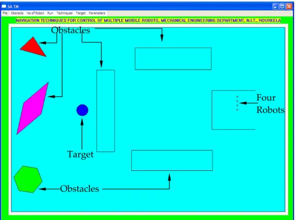
annealing‐neuro‐fuzzy technique (Intermediate Scenario ‐ II)... 214 Figure a.1. Obstacles... 220 Figure a.2. Fifteen mobile robots... 220
Figure a.3. View of the software (ROBOPATH) front‐end user for navigation of multiple mobile robots... 221 Figure b.1. A simple Petri Net model... 225 Figure b.2. A simple firing example using Petri Net model... 227 Figure c.1. Khepera II robot... 230 Figure c.2. Boe‐Bot robot... 231 Figure c.3. Hemisson Robot... 232 Figure c.4. Koala Robot... 233 Figure d.1. The main window of See5... 238 Figure d.2. The Main dialog box... 238
List of Symbols
∨= Aggregate (Union)Λ= Minimum (Intersection) ∀= For all
α i = A positive scaling factor
desire
θ = Desire output from the neural network
actual
θ = Actual output from the neural network µ= Fuzzy membership function
0 =
ρ Positive constant denoting influences of the obstacle on the robot
(
)
ρ
i
obs
q , q = The minimum distance from the robot ‘q’ to the obstacle
ω= Angular velocity of the wheeled mobile robot
l
ω = Angular velocity of the left driving wheel
r
ω = Angular velocity of the right driving wheel Al = Point of contact of the left driving wheel
Ar = Point of contact of the right driving wheel
B = Wheel base of the mobile robot C = Centroid of the mobile robot d = Distance between C and M
[ ]1 1
d = Left obstacle distance from the robot
[ ]1 2
d = Front obstacle distance from the robot
[ ]1
E = Objective function
( )
att
F x = The attractive potential force FD = frontdist = Front obstacle distance FLC = Fuzzy Logic Controller
(
)
rep i
F obs = The repulsive potential force HA = Target angle = Heading angle i = 1 to n, n is number of obstacles LD = leftdist = Left obstacle distance
LV = leftvelo = Left wheel velocity of a robot M = Mid‐point of the rear wheel base
Med = Medium Negative = Left Turn OA = Obstacle Avoidance P = Instantaneous center Positive = Right Turn
q = [x, y] = The robots position in the workspace r = Radius of the two rear drive wheel
RD = rightdist = Right obstacle distance
RV = rightvelo = Right wheel velocity of a robot
T = Control parameter TS = Target Seeking
[ ]1
( )
att
U q = The attractive potential function for robot with respect to target
(
)
rep i
U obs = The repulsive potential function for robot with respect to obstacle
Total
U = Total potential influences on the robot V = Translation velocity of a mobile robot vel = velocity
Vl = Left real wheel driving velocity
Vr = Right real wheel driving velocity
VF = Very Fast VN = Very Near VS = Very Slow
WMR = Wheeled mobile robot
1 Introduction
This chapter gives an overview of the research work reported in this thesis. First, the background of the research and the chosen problem domain are outlined. Then, the objectives of this research work are described. Finally, an outline of the thesis contents is provided.
1.1 Background
The most significant challenges confronting autonomous robotics lie in the area of automatic motion planning. Navigation of mobile robots in dynamic environments needs to cope up with large amounts of uncertainties that are inherited from natural environments. Thus navigation of mobile robots deals with large spectrum of different technologies and applications. It draws on some primitive techniques, as well as some of the most advanced technique.
Investigations in the field of navigation of mobile robot gained an extensive interest among the researchers since last two decades. This is chiefly due to the necessity to replace human intervention in dangerous environments (e.g. nuclear, space, military mission, harmful material handling, interplanetary explorations etc.) or to develop a helpful automated device for some classical tasks (e.g. cleaning, supervision, carriage, etc.). In today’s flexible manufacturing system environment, the autonomous mobile robot plays a very important role. It is used to transport the parts from one workstation to others, load unload parts, remove any undesired objects from floors, and so on. Without autonomous mobile robot, the work stations, the CNC machines, machining centers will only be scattered and isolated machine tools and they will never become the part of an automated manufacturing system. It is the mobile robot that connects the
continuously, automatically and at a low cost, manufacture a variety of parts. So mobile robot navigation encompasses a number of skills, from high‐level capabilities such as exploring the surrounding environment, building a global map of the environment and planning a path towards a specific goal, to the execution of elementary low level action like avoiding collisions with obstacles. Numerous methods have been proposed, however, they don’t guarantee a solution for the mission because of deadlock problem occurrences. The reason is that the robot does not have a high‐level map reading ability.
The goal of autonomous mobile robotics is to build physical systems that can navigate purposefully and without human intervention in cluttered unknown environments. The development of techniques for autonomous robot navigation is one of the major focusing areas in the current investigation. This trend is motivated by the current gap between the available technology and the new application demands, e.g., the current industrial robots have low flexibility in autonomy. These robots perform pre‐programmed sequences of operation in highly constrained environment and are not able to operate in new environments.
Autonomous navigation systems are usually classified in the following categories according to the characteristics of the environment in which they have to move: i) structured or known environment, ii) semi structured or partially known environment and iii) unstructured or unknown environments.
Another classical way is to send the robot to discover its world and define some landmarks that can be used for navigation. In similar conditions, the robot relies heavily on its sensors, map making and updating. However, natural workspaces present a large amount of uncertainties and mapping techniques. These are time and memory consuming. Hence the need of an intelligent
approach such as soft computing techniques can cope with all uncertainties present in the environment. Soft computing techniques involve computations related to neural network, fuzzy logic technique, genetic algorithm, simulated annealing and others. Researchers and practitioners are finding these methods increasingly useful in various problem domains, not only they are new but also they have inherent capabilities of handling imprecision and uncertainty with a reasonable amount of computational complexity. Details of their work are cited in the literature survey.
One of the earliest mobile robots being Shakey, a vision‐guided autonomous mobile machine designed at Stanford Institute in 1966 [1]. Research works have concentrated on the control of individual mobile robots. Within the last decade, there has been an interest among the scientists and researchers to co‐ ordinate multiple mobile robots. This interest has stemmed both from practical considerations such as multiple robots are able to handle tasks that individual machine cannot do, for instance carrying large, bulky and heavy loads and desire to create artificial systems that mimic nature in particular by exhibiting some of the primary behaviours observed in human societies.
1.2 Aims and Objectives of this Research
The overall aim of this research is to explore the application of artificial intelligence techniques to navigate multiple mobile robots. In this thesis, fuzzy logic, neural network, rule‐based, potential field navigation and simulated annealing techniques have been used to solve mobile robots navigation problems. In particular, the research aims to determine whether hybrid techniques are appropriate for implementing as navigational algorithms for multiple mobile robots. This type of investigation is justified in this thesis.
The main objectives of the present work for navigation of the multiple mobile robots are:
¾ To compute the heading angle for the mobile robots in terms of left wheel velocity and right wheel velocity of the robot.
¾ To develop fuzzy logic techniques using different membership functions. ¾ To build up a neural network technique.
¾ To create a hybrid neuro–fuzzy technique. ¾ To develop rule‐base technique.
¾ To build a hybrid system of rule‐based‐neuro‐fuzzy technique. ¾ To develop an efficient potential field method.
¾ To formulate a hybrid potential‐field‐neuro‐fuzzy technique.
¾ To develop potential‐field‐simulated‐annealing‐neuro‐fuzzy technique for avoidance of local minima during navigation.
¾ Simulation and experimental verifications of the above outlined techniques are to be carried out.
1.3 Outline of the Thesis
The thesis is divided into eight chapters.
¾ Following the introduction, Chapter‐2 is devoted to a survey of the literature on mobile robot navigation.
¾ Chapter‐4 deals with the analysis of a proposed fuzzy logic technique with three types of membership functions to navigate mobile robots in a static as well as dynamic environment.
¾ The first part of Chapter‐5 describes a neural network technique and the second part deals with neuro‐fuzzy technique for navigation of multiple mobile robots.
¾ Chapter‐6 presents rule‐based techniques, starting with simple rule‐based navigation technique and concluding with an advanced rule‐based‐neuro‐ fuzzy technique.
¾ Chapter‐7 is divided into two sections. First section deals with navigation of mobile robots using potential field method. Second section discusses a hybrid technique i.e., potential‐field‐neuro‐fuzzy technique.
¾ Chapter‐8 confers about the optimisation of potential field method with use of simulated annealing. Finally the hybrid potential‐field‐simulated‐ annealing‐neuro‐fuzzy technique is used for navigation of mobile robots. ¾ In Chapter‐9 conclusions of the research are summarized and scopes for
further work are suggested.
2 Literature Review
This chapter reviews the literature in the area of mobile robot navigation, focusing on intelligent techniques for navigation control.
2.1 Introduction
A motion planner is an essential component of a robot that interacts with the environment. Without the motion planner, a human operator has to constantly specify the motion for the robot. A considerable amount of research has been done on the development of efficient motion‐planning algorithms. The motion‐ planning problem has been solved in a theoretical sense for the general problem. Recently the coordinations between mobile robots for obstacle avoidance and target seeking are carried out by the researchers using various methods. Soft computing techniques such as fuzzy logic, neural network and genetic algorithm are considered for expressing the subjective uncertainties in human mind. The ultimate goal of mobile robotics research is to endow the robots with high intellectual ability, of which navigation in an unknown environment is achieved by using on‐line sensory information. A significant amount of research efforts have been devoted to this area in the past decades few of which are reviewed below:
2.2 Mobile Robot Navigation
Navigation of a robot is the control of motion from a start point to an end point in a workspace following a path that is either a curve or a series of jointed segments. Many researchers in the area of mobile robots navigation have developed two key approaches. One is functional or horizontal decomposition
[2] (Figure 2.1) and the other is behavioural or vertical decomposition [3] (Figure 2.2). The former approach is sequential and involves modelling and planning. The latter approach is parallel and requires exploration and map building. Both approaches use many distinct sensory inputs and computational processes. Decisions such as left turn, right turn, run or stop are made on the basis of those inputs [4].
Levitt et al. [5] defined the aim of navigation control as providing answers to the following three questions: (a) Where am I? (b) Where are other places relative to me? (c) How do I get to other places from here? Question (a) is the problem of identifying the current location. Questions (b) and (c) relate to avoid obstacles and move towards the target. To address both issues a mobile robot must have a way to perceive its environment. Some authors have proposed that use of single sensor (e.g., sonar, laser, vision and infrared) [6, 7, 8, 9, 10, 11, 12] where as others have recommended heterogeneous systems using different types of sensors [13, 14, 15].
Using the environment information perceived at each instant as well as data from previous instants, a strategy should be pursued to enable the robot to reach its target position without colliding with obstacles. Researchers have used many techniques for obstacle avoidance [16, 17, 18, 19]. These techniques, together with the different sensors employed [20, 21] are reviewed below.
Figure 2.1. Flow diagram of the horizontal decomposition method for the navigation of a mobile robot.
SENSING PERCEP TION MOTOR CO NTROL MODELL ING PLANN ING EXECUTION ENVIRONMENT ACTION
Figure 2.2. Flow diagram of the vertical decomposition method for the navigation of a mobile robot.
SENSING ACTION ENVIRONMENT BUILDING MAP EXPLORE WANDER AVOID
2.3 Kinematic Analysis of Mobile Robots
2.3.1 Introduction
A wheeled mobile robot (WMR) is a wheeled vehicle, which is capable of autonomous motion. An increasing interest in mobile manipulators observed recently in the literature has two sources: first, excellent performance characteristics of mobile manipulators and second, challenging motion planning and control problems [22, 23, 24, 25, 26, 27].
2.3.2 Kinematic Analysis for Mobile Robot Navigation
Alexander et al. [28] have developed the relationship between the rigid body
motion of a robot and the steering and drive rates of wheels. They have used the
forward and inverse kinematics to a WMR with simple wheels that is maneuvering over a horizontal plane. Their method guarantees that rolling without skidding or sliding can occur in robot motion. Muir et al. [29] have also
developed the motion of wheeled mobile robots on flat terrain. Tsuchiya et al. [30] have discussed motion control of a two‐wheeled mobile robot. They have designed a controller using kinematic model in which the wheels of the robot do not skid at all. Mester [31] has dealt with the modelling and control strategies of the motion of wheeled mobile robots. The model of the vehicle has two driving wheels and its angular velocities are independently controlled. He has analysed the vehicle kinematics model and the control strategies using a feed forward compensator.
Hwang et al. [32] have surveyed the work on gross‐motion planning, including motion planners for point robots, rigid robots, and manipulators in stationary, time‐varying, constrained, and movable‐object environments. They have explained general issues in motion planning. Chakraborty et al. [33] have
studied the problem of kinematic slip for mobile robots moving on uneven terrain. The simulation results of their developed technique show that the three‐ wheeled mobile robot with torus shaped wheels and passive joints can negotiate uneven terrain without slipping.
2.4 Fuzzy Logic Technique
2.4.1 Introduction
Fuzzy control concepts are useful in both global and local path planning tasks for autonomous mobile objects. Humans have a remarkable capability to perform a wide variety of physical and mental task without any explicit measurements or computations. Examples of everyday tasks are, driving in city traffic, parking a car, and cleaning of house. In performing such familiar tasks, humans use perceptions of time, distance, speed, shape, and other attributes of physical and mental objects. Perceptions are described by propositions drawn from a natural language, in which the boundaries of perceived classes are fuzzy. It is highly desirable to capture the expertise of a human mind and to utilise the knowledge to develop autonomous navigation strategies for mobile robots. Fuzzy logic provides a mean towards accomplishing this goal. Fuzzy logic provides a formal methodology for representing and implementing the human expert’s heuristic knowledge and perception‐base actions. Using the fuzzy logic framework, the attributes of human reasoning and decision‐making can be formulated by a set of simple and intuitive IF (antecedent)–THEN (consequent) rules, coupled with easily understandable and natural linguistic representations.
2.4.2 Fuzzy Logic Technique for Mobile Robot Navigation
motions to bring together parts in a specific configuration has become essential for several applications, the traditional solutions for path planning have failed for complicated environments as they result computationally infeasible and restricted to their performance, Latombe [34] and Fraichard [35]. Motivated by Zadeh [36] and explored by Mamdani et al. [37] and Kickert et al. [38], many researchers have used fuzzy logic techniques successfully in numerous control systems such as control of mobile robot navigation. Examples of work relating to fuzzy logic for the navigation of mobile robot are described below:
Lacroix et al. [39] have presented a complete autonomous system which is capable to perform autonomous navigation in a natural, unstructured and totally unknown environment. The system is endowed with several complex capabilities: environment modelling, localization, trajectory planning and exploring strategies. They have executed the navigation behaviour based on terrain quality. The terrain is classified in four distinct categories: flat, uneven, obstacle, and unknown. Goldberg et al. [40] and Sing et al. [41] have computed an analytical traversability measure for the terrain, based on stereo range data. Roll, pitch, and roughness of terrain cells are estimated from the viewable terrain image. Roll and pitch are calculated by using a least squares method to fit a plane to the range data, and roughness is computed as the residual of the fit. These measures are normalized in the range of [0, 1] and a goodness value is determined, based on the minimum value of the three parameters. A path finder then evaluates the traversability along predetermined candidate paths by taking a weighted combination of the goodness and certainty values. Langer et al. [42] have focused on the development of a navigation system that generates recommendations for vehicle steering, based on the distribution of untraversable terrain regions. A new design for behaviour‐based navigation of field mobile