IMU Based Tracking and Stabilization System
Aaron Barton
Senior Project
ELECTRICAL ENGINEERING DEPARTMENT California Polytechnic State University
San Luis Obispo March 2014
Contents
Abstract ... 5
Chapter 1: Introduction ... 5
Chapter 2: Requirements and Specification ... 6
Customer Needs Assessment ... 6
Requirements and Specifications ... 6
Chapter 3: Functional Decomposition ... 7
Level 0 Block Diagram ... 7
Level 1 Block Diagram ... 9
Software Flowchart ... 11
Chapter 4: Component Design ... 12
Hardware ... 12 Power Supply ... 13 Software ... 13 Standard Functions ... 13 Custom Functions ... 14 Chapter 5: Integration ... 17 Chapter 6: Testing ... 18 Position ... 19 Rotation ... 20 Chapter 7: Conclusion ... 20 References ... 21 Appendix A: BOM ... 22
Appendix B: Source Code ... 23
Main Source Code ... 23
IMU Header File ... 29
Appendix C: Final Project Schematic ... 31
Appendix D: Senior Project Analysis... 31
Summary of Functional Requirements ... 31
Economic ... 32
If manufactured on a Commercial Basis ... 33
Environmental ... 33
Manufacturability ... 33
Sustainability ... 34
Ethical ... 34
Health and Safety... 34
Social and Political ... 35
Development ... 35
References ... 35
Appendix E: General PID Control Algorithm ... 38
List of Figures Figure 1: Zero Level Project Block Diagram ... 7
Figure 2: Level One Project Modules ... 9
Figure 3: Flowchart of Core Software ... 12
Figure 4: Power Supply Schematic ... 13
Figure 5: Motor Control Code ... 16
Figure 6: Rotation Calculation Code ... 17
Figure 7: Project Box Interior ... 18
Figure 8: Simulated Position Calculations ... 19
Figure 10: Project Schematic ... 31
List of Tables
Table 1: Inertial Tracking System Requirements and Specifications ... 7
Table 2: Top Level Project Functionality ... 8
Table 3: IMU Module Functionality ... 9
Table 4: μC Module Functionality ... 10
Table 5: Motor Driver Module Functionality ... 10
Table 6: Stepper Motor Module Functionality ... 10
Table 7: Power Supply Module Functionality ... 11
Table 8: Laser Pointer Module Functionality ... 11
Table 9: Functions Defined in Microcontroller Datasheet ... 14
Table 10: Two's Complement Conversion... 14
Table 11: Terminal Debug Printing ... 14
Table 12: Timer Interrupts Setup ... 15
Table 13: Data Reading Function ... 15
Table 14: Sensor Data Combination ... 16
Table 15: Senior Project Results ... 20
Table 19: Critical Components BOM ... 22
Table 17: Complete Source Code ... 29
Table 18: Source Code Header File ... 30
Abstract
The objective of this project is to develop a system that can track a user selected point in space given displacement, vibration and rotation of the device. Stabilization systems are used in various forms over the years, with the military amongst the foremost adopters. More recently, with the increasing popularity of quad-copters for RC hobbyists, and small cameras capable of take high quality video during recreational sports such as skiing or mountain biking, the need has emerged for a cheaper, more accessible version of stabilization systems for use in photography. Additionally, while some devices do exist for hobbyists can take vibration free video, few devices provide for any kind of target tracking, rather, they merely point in the direction of motion of the system. The system proposed here can track a target while adjusting for any motion that a sitting person can impart on it. However, due to difficulties in getting clean sensor readings, only two axis rotations can be handled.
Chapter 1: Introduction
Tragically, I want to work in a field that does not exist as an industry, but rather as a research area; as currently the field of humanoid robotics has not progressed to production industries.
However, in the interim, other area of autonomous operation are just as interesting. Furthermore, I wanted a project that combined by my technical electives, consisting of DSP, Power Electronics, and Mechatronics, with my internship experiences as a manufacturing and applications engineer in a robotics related design project.
With these parameters in mind, I decided to choose a project that could replicate the tracking ability of the human eye. The ability of the human eye to smoothly follow an object of interest, while accounting for the rotation of the head and the movement of the body, has always interested me. Therefore, I decided to build an inertial measuring unit (IMU) based system that could track a target through using sensor readings to control a series of motors.
On top of the desire for a robotics based project, I have two major secondary goals; namely, that the final design has a professional finish and robust construction. Should the opportunity arise, I want to demonstrate the operation of my final project, perhaps to potential employers, without having to worry if the device can survive transportation and arrive at its destination in operating condition. From these considerations, the following three items are the guiding principle of this project. First, build a system that can track a target, second, build a system that demonstrates my interest and ability in the field of robotics, and third, build a system that robust, professional looking, and easy to transport and demonstrate the designs functionality.
Chapter 2: Requirements and Specification
Customer Needs AssessmentIn this project I will design and building everything by myself, and the project is entirely built around my interest in robotics. Therefore, as the primary customer, I want this project to fulfill two main goals. First, it should be a project that can indicate my interest in robotics to potential
employers, and secondly, it should be a professional, sturdy device that I can easily carry around show to potential employers when finished.
This project should accomplish the first goal by making use of sensor measurements and motors to help the IMU Based Tracking System (IMTS) adapt to a changing environment. The second goal will be accomplished by making the device portable, making it easily carried around, and well built, to resist damage during transportation.
Requirements and Specifications
The primary requirement is the ability to hold the laser beam within 3 inches of the target from 5 feet away. This requires a motor to control its angle within 3 degrees or less, and allows for 5% error in target tracking. The previous requirement needed 1 degree resolution and less than 2% error in tracking. While this doable, the price for the components would be prohibitive. Therefore the requirements were relaxed.
The newest requirement is that the motors only need to rotate 180°. This was added after it was realized that continuous rotation would make electrical connections difficult to keep from breaking. The primary safety consideration is that laser pointer will not be active while if the device cannot account for the users motion fast enough. To account for this the laser must be deactivated if it cannot be kept on the target.
The remaining requirements, such as battery power and weight, are included to make the device simple to use and demonstrate. By fulfilling these requirements, the final device will be a portable design that is quick and easy to use.
Marketing Requirements
Engineering
Specifications Justification
7 Hold laser pointer beam within 3 inches of stationary target from 5 feet way
A laser pointer will serve as a visual indicator of target tracking
5,7 Fix laser on the target 1 second after the end of user motion
The system must quickly refocus on the target after user motion
6 Deactivate laser if laser moves 1 foot off the target
For safety reasons the laser pointer must deactivate if it moves off the target 4,3 System must run a minimum of 5 minutes
during constant usage using 1 battery
A 5 minute battery life is a tradeoff between weight, performance and portability 2 The user can fix the system on the target in a
1 minute timeframe
The user must be able to quickly setup the system to track a target
1,2,3 System weight must not exceed 10 pounds A heavy design cannot be held by one hand 5 Motors must have 180° of motion Motors must not rotate continuously to prevent
power and signal connections from getting broken off
Marketing Requirements
1. The user can hold the device with one hand 2. Easy to operate
3. Portable 4. Battery powered
5. Track any target in front of the device 6. Safe
7. Hold focus on any point in a room
Table 1: Inertial Tracking System Requirements and Specifications
Chapter 3: Functional Decomposition
Level 0 Block DiagramThe top level block diagram of the project is shown below as Figure 1. This is the level at which the user interacts with the system, as they can move the device around, need to keep the battery charged, can select targets and turn the device on and off. Based on these inputs, the user will see the LTS adjust the orientation of the laser pointer to keep it pointed at the target, and turn the laser off if it cannot do so.
Figure 1: Zero Level Project Block Diagram
The power supply in this case will be based on a 12V battery. This was chosen as the IMU and microcontroller ( μC) need at least 5V to operate. However, motor drivers will take more than this to power the motors. Some common battery voltages are 6V and 8.4V. The latter voltage would
User Motion User Position
Battery Power Target Selection
Laser Tracking System
System On/Off
System Motion Laser On/Off
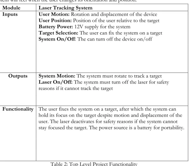
work, but only barely. To account for battery voltage drop during usage, it was determined that two 6V batteries in series would work best as the power source. If RC hobbyist batteries are used, their size and weight will be minimal. The user motion and position inputs in Table 2 are the forces that the system will feel when the user changes its orientation and position.
Module Laser Tracking System
Inputs User Motion: Rotation and displacement of the device
User Position: Position of the user relative to the target
Battery Power: 12V supply for the system
Target Selection: The user can fix the system on a target
System On/Off: The can turn off the device on/off
Outputs System Motion: The system must rotate to track a target
Laser On/Off: The system must turn off the laser for safety
reasons if it cannot track the target
Functionality The user fixes the system on a target, after which the system can
hold its focus on the target despite motion and displacement of the user. The laser deactivates for safety reasons if the system cannot stay focused the target. The power source is a battery for portability.
Table 2: Top Level Project Functionality
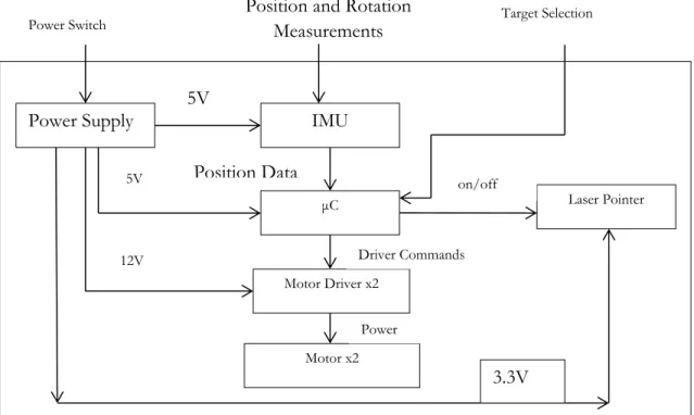
Level 1 Block Diagram
Figure 2: Level One Project Modules
The IMU module, described below in Table 4is the most important component in the design. The system does not have the ability to aim the laser pointer more accurately than the IMU can measure the movements the system as a whole experiences. The IMU data will need to undergo filtering to prevent the microcontroller from issuing commands based on noisy data.
Module IMU
Inputs Position and Rotation Measurements: Roll,
pitch, yaw and acceleration measurements
5V: Power for the sensor
Outputs Position Data: Inputs are interpreted in terms
of position and orientation, and output by SPI
Functionality Senses the motion that the system undergoes
Table 3: IMU Module Functionality
The microcontroller used for the project, the Mega2560, was chosen for the simple reason that I already own one and I have previous Ardunio based programming experience. The
microcontroller accomplishes three main tasks for this project. First, it takes in the IMU senor readings. Next, it issues commands to the motor driver based on its processing of the IMU data. Finally, this module also turns the laser pointer off if it realizes that the motors cannot keep it on the target. This is a safety critical task.
Module μC
Inputs Position Data: IMU sensor measurements,
Power Supply IMU
μC Laser Pointer
Motor Driver x2
Motor x2
Position and Rotation Measurements
Power Switch Target Selection
Position Data 5V 5V 12V Driver Commands on/off Power 3.3V
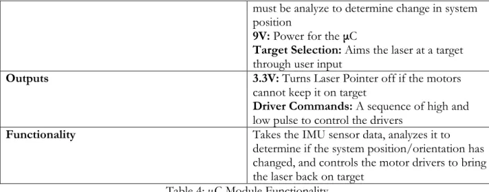
must be analyze to determine change in system position
9V: Power for the μC
Target Selection: Aims the laser at a target
through user input
Outputs 3.3V: Turns Laser Pointer off if the motors
cannot keep it on target
Driver Commands: A sequence of high and
low pulse to control the drivers
Functionality Takes the IMU sensor data, analyzes it to
determine if the system position/orientation has changed, and controls the motor drivers to bring the laser back on target
Table 4: μC Module Functionality
The motor driver functionality outlined in Table 5 below is simple. Based on a series of command pulses from the microcontroller, this component sources current to the motor coils, which in turn will control the amount motor shafts rotate. This is the highest power module in the system, and safety precautions should are required during construction and operation. While only one driver block is shown, the project requires one for each of the motors.
Module Motor Driver
Inputs Driver Commands: A sequence of high and
low pulses that tell the driver how to power the motor coils
12V: Power for the motor driver
Outputs Power: Pulses of current at a set voltage to
move the shaft of the motors.
Functionality Based on μC inputs, the driver will send current
to the motor, which will rotate a set amount Table 5: Motor Driver Module Functionality
The motor is the second most important component in this project; and presents another major factor in limiting the accuracy of the final design. The motor performance directly affects two important engineering requirements as this component directly effects for both the time taken to move the laser back to the target after experiencing a force, and how closely the laser can be pointed at the target.
Module Motor
Inputs Power: A set voltage and varying current to
energize the motor coils and rotate the motor shaft a set amount
Outputs Controls the orientation of the laser pointer
Functionality Based on the rotations of the two motors, the
laser pointer will be continuously pointed at the target
The power supply, detailed in Table 7 below, requires additional internal modules to provide the different voltage needed. As part of the marketing requirements, the must be portable; this requires a battery as a power source. However, the system needs two different output levels, 5V for the embedded electronics, and relatively low current and 12V for the motor drivers, which will probably require several amps. While not strictly part of the design, the battery needs a charger that can charge the battery type selected.
Module Power Supply
Inputs Power Switch: User can switch the power
supply on/off to turn the system on/off
Outputs 9V: Power for the μC
12V: Power for the Motor Drivers
3.3V: Power for the Laser Pointer
Functionality Provide power for the system
Table 7: Power Supply Module Functionality
The laser pointer module is the simplest component of this project. If the microcontroller decides that it is safe for the laser to be on, then it will provide power for the laser to operate. Otherwise, the laser pointer deactivates. This module exists to provide a visual indicator of target tracking.
Module Laser Pointer
Inputs 3.3V: Power from the μC, can be switched off if
the laser is off target
Outputs Visual demonstration of target tracking
Functionality Provides visual demonstration of target tracking
Table 8: Laser Pointer Module Functionality Software Flowchart
The above sections detail the general, primarily hardware based, modules that need designed, and the connections between these modules. However, these blocks do not include the general software flowchart, which is assumed to be part of the μC module. Accordingly, it is presented here. After setup, the code enters an endless while loop. Data is sampled at a rate of 50 Hz according to a timer driven interrupt. This precise sampling of data is done to ensure that calculations based on data are accurate. If an interrupt is generated, the program takes the current gyroscope
measurements and either saves them, ignores them, or adjusts the motor positioning. The details of this operation are discussed in later sections.
Figure 3: Flowchart of Core Software
Chapter 4: Component Design
The above sections describe the form that I thought my project would take and the thought process behind my design choices. This chapter describes the actual design of the modules described above in Chapter 3: Functional Decomposition. Integration with other modules will be covered in later chapters.
Hardware
Minimal original electrical design was needed for this project aside from the power supply, which is described below. Much of the electrical hardware design was based on correctly wiring the connections between the μC, IMU, drivers, etc. The complete wiring diagram can be seen in Figure 9: Project Schematic. Most of the components used were purchased already attached to break out boards, to make the needed connections between the IMU, motor drivers, and μC, it was necessary
Read Gyro Data
Is system rotating? Was system previously rotating? No No
Store the data Calculate rotation
Run motors
Yes Read Data Interrupt
to read the original part datasheets [5], [6] as well as the breakout board manufactures board
specifications [4], [8]. Most of the connections are self-explanatory after reading the datasheets. The connections from the drivers to the μC can use any free μC pins.
Power Supply
The power supply is based around an 11.1V Lithium Polymer (LiPo) battery (12.6V fully charged). Two different voltages were derived from this, 9V for the fan and microcontroller, and 3.3V for the laser pointer. The schematic, show below as Figure 4, was entirely derived from the datasheet for the LM317 [1]; the equation controlling this circuit is
.
Figure 4: Power Supply Schematic
Software
Standard Functions
The software functions can be placed in two different categories; those that perform tasks according to established standards, such as I2C communication, USART communication, etc., and
those perform custom processes, such as combining 2 8-bit numbers into 1 16 bit number, and sequential read operations of the IMU. Accordingly, the functions listed below will not be described in detail as they were taken almost entirely from [2].
void usart_send( uint8_t data )
void usart_init(uint16_t baudin, uint32_t clk_speedin) void initilize_TWI()
int write_TWI(uint8_t slave_Address_W, uint8_t sub_Address, uint8_t data) int read_TWI(uint8_t slave_Address_W,uint8_t sub_Address,uint8_t,
slave_Address_R)
Table 9: Functions Defined in Microcontroller Datasheet
The USART_SEND function, used for transmitting data from the microcontroller to a terminal program, was taken directly from page 211 of [2], and USART_INIT from page 212. Both of these functions use hardware peripherals on the microcontroller; the only user determined portions are the data to transmit. INITILIZE_TWI sets the TWI bus speed to 400 kHz; the pin setting for this function is defined in the atmega2560 datasheet. The functions WRITE_TWI and READ_TWI use the Two Wire Interface (TWI, Atmel’s version of I2C) peripheral hardware. These functions can be developed careful reading of the information in section 24 of [2]. For my part, I had access to a tutorial from my embedded systems class, CPE 329; the TWI read/write functions are taken entirely from this source [3]. This source code for these functions can be viewed in Table 17.
Custom Functions
The raw data readings from the IMU are in binary twos complement form. To perform calculations on these measurements, the measurements must be converted out of twos complement form by inverting each bit and adding 1 to the result. The code for this function is shown in Table 10 below.
int data_convert_16(int16_t data) //used to convert the raw data out
{ //of twos complement
int16_t two_comp = 0;
two_comp = data ^ 0xFFFF; two_comp = two_comp + 1;
return two_comp; }
Table 10: Two's Complement Conversion
Debugging messages are crucial for development of any system. The code shown below in Table 11 was developed to enable easy printing of messages to a terminal.
void string_write(char *pointer1) //used for debugging
{ //to print messages to terminal
for(int j=0; j<strlen(pointer1); j++) /*Writes Message to Row 1*/
{
usart_send(pointer1[j]); }
}
For accurate calculations on measured data, it is crucial that the time between measurements is measured as accurately as possible. To ensure accurate timing, IMU data was read based on timer triggered interrupts. The code shown below in Table 12 generates interrupts at 50 Hz.
void init_timer3(void) //set the timer used to control IMU readings
{ //50 Hz rate
TCCR3B = (1<<WGM12)|(1<<CS12); //Enables CTC Mode, Prescaler is 256
OCR3A = 1250; //Compare Value. Waveform Frequency = 16MHz/Length/(OCR3A + 1)
TIMSK3 = (1<<OCIE3A); //Enable timer interrupts
}
Table 12: Timer Interrupts Setup
The IMU used measure 3 16 bit values and stores each reading in two 8-bit registers. The code shown below reads all 6 registers and stores the results for later analysis.
void read_3axis_data(uint8_t *axis, uint8_t slave_Address_W, uint8_t sub_Address, uint8_t slave_Address_R)
{ /*
this function is used to read all 6 of the data registers on the gyro or ACC it sequentially steps though the registers, calling a single read operation each time. Data is combined and processed later. This is possible as device register addresses are sequential.
*/ for(int j=0;j<6;j++)
{
*axis = read_TWI(slave_Address_W, sub_Address, slave_Address_R); axis++;
sub_Address++; }
}
Table 13: Data Reading Function
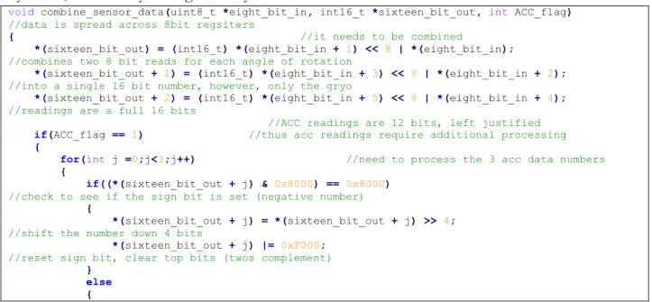
The function shown below in Table 14 combines the two 8-bit numbers into the full 16 bit number. However, while acceleration data is stored in a 16 bit number, the measurement is actually a 12-bit number. This function handles gyroscope readings, 16-bits, acceleration readings, 12-bits, and correctly handles positive and negative numbers. The data being processed was read in with the low byte first, followed by the high data byte.
void combine_sensor_data(uint8_t *eight_bit_in, int16_t *sixteen_bit_out, int ACC_flag)
//data is spread across 8bit regsiters
{ //it needs to be combined
*(sixteen_bit_out) = (int16_t) *(eight_bit_in + 1) << 8 | *(eight_bit_in);
//combines two 8 bit reads for each angle of rotation
*(sixteen_bit_out + 1) = (int16_t) *(eight_bit_in + 3) << 8 | *(eight_bit_in + 2);
//into a single 16 bit number, however, only the gryo
*(sixteen_bit_out + 2) = (int16_t) *(eight_bit_in + 5) << 8 | *(eight_bit_in + 4);
//readings are a full 16 bits
//ACC readings are 12 bits, left justified
if(ACC_flag == 1) //thus acc readings require additional processing
{ for(int j =0;j<3;j++) //need to process the 3 acc data numbers
{
if((*(sixteen_bit_out + j) & 0x8000) == 0x8000)
//check to see if the sign bit is set (negative number)
{
*(sixteen_bit_out + j) = *(sixteen_bit_out + j) >> 4;
//shift the number down 4 bits
*(sixteen_bit_out + j) |= 0xF000;
//reset sign bit, clear top bits (twos complement)
} else {
*(sixteen_bit_out + j) = *(sixteen_bit_out + j) >> 4;
//sign bit not set, shift number down 4 bits
//clear top 4 bits, they hold no information
} } } }
Table 14: Sensor Data Combination
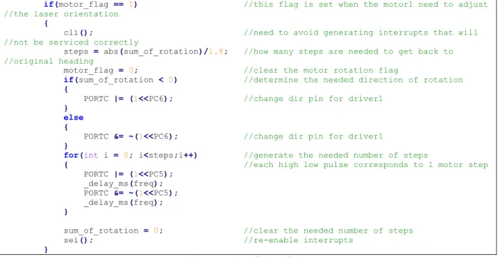
The code shown below is used to control the motors in the real-time loop portion of the code. When the motor flag is set high, this means that the measured rotation has stopped and the motor must rotate to adjust the orientation of the laser pointer. Accordingly, the code calculates the number of steps needed, the required direction, and generates the steps.
if(motor_flag == 1) //this flag is set when the motor1 need to adjust //the laser orientation
{
cli(); //need to avoid generating interrupts that will //not be serviced correctly
steps = abs(sum_of_rotation)/1.8; //how many steps are needed to get back to //original heading
motor_flag = 0; //clear the motor rotation flag
if(sum_of_rotation < 0) //determine the needed direction of rotation
{
PORTC |= (1<<PC6); //change dir pin for driver1
} else {
PORTC &= ~(1<<PC6); //change dir pin for driver1
}
for(int i = 0; i<steps;i++) //generate the needed number of steps
{ //each high low pulse corresponds to 1 motor step
PORTC |= (1<<PC5); _delay_ms(freq); PORTC &= ~(1<<PC5); _delay_ms(freq); }
sum_of_rotation = 0; //clear the needed number of steps
sei(); //re-enable interrupts
}
Figure 5: Motor Control Code
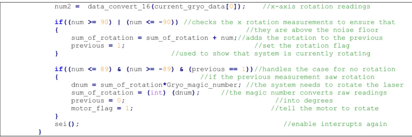
The code shown below in Figure 6 handles gyroscope data calculations. The first portion reads in the data, and combines it into 16-bit numbers. The second portion checks to see that it is above the noise floor, and updates the measurements total and logic accordingly. Note that
Gyro_magic_number was determined empirically, and is a number that when multiplied by one gyro data sample, converts the raw number into degrees of rotation. This number only works for the 50 Hz data rate.
if(read_data_flag == 1) {
cli(); //do not want to generate new read requests before
read_data_flag = 0; //first one is //finished. Clear read flag
read_3axis_data(gryo_reading, 0xD6, L3G_OUT_X_L, 0xD7); //read the ACC
combine_sensor_data(gryo_reading, current_gryo_data, 0); //combine the 2 8 //bit numbers
read_3axis_data(ACC_reading, 0x32, LSM303_OUT_X_L_A, 0x33); //read the Gryo
combine_sensor_data(ACC_reading, current_ACC_data, 1); //combine the 2 8 bit numbers //(12 real data bits)
//ACC data is not currently being used
num2 = data_convert_16(current_gryo_data[0]); //x-axis rotation readings
if((num >= 90) | (num <= -90)) //checks the x rotation measurements to ensure that
{ //they are above the noise floor
sum_of_rotation = sum_of_rotation + num;//adds the rotation to the previous
previous = 1; //set the rotation flag
} //used to show that system is currently rotating
if((num <= 89) & (num >= -89) & (previous == 1))//handles the case for no rotation
{ //if the previous measurement saw rotation
dnum = sum_of_rotation*Gryo_magic_number; //the system needs to rotate the laser
sum_of_rotation = (int) (dnum); //the magic number converts raw readings
previous = 0; //into degrees
motor_flag = 1; //tell the motor to rotate
}
sei(); //enable interrupts again
}
Figure 6: Rotation Calculation Code
Chapter 5: Integration
The previous chapters show the motivation, conceptual design and actual design of the needed components. During the design phase each component was built and tested with the minimum number of modules to ensure basic functionality. The power supply was designed, supplied with power from a bench top power supply, and then connected to the fan and laser pointer to ensure that those devices could run off the 9V and 3.3V sources. The IMU was wired to the μC according to the connections shown in Figure 9, and the functions in the software section were written to enable communication between the device and microcontroller.
Finally, the μC was wired to the control pins one motor driver, which was in turn wired to one stepper motor [7], [9]. Power for the driver was again supplied by a bench top power supply. A simple program was written that would run the stepper continuously in one direction. After this verified that the devices were wired correctly, the micro-stepping abilities were tested as the data sheet was unclear how low the motor could actually micro-step at. Testing revealed that the driver and motor could step down to 1/32 of a step, where a full step is 1.8 degrees.
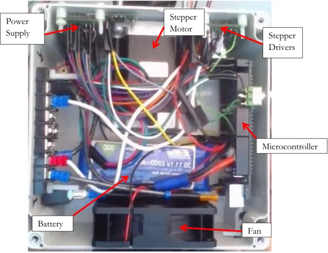
At this point the project consisted of various modules that could work together but it was not yet possible to assemble them into a complete functional design. To get a functional design, everything had to be mounted inside a project, shown below as Figure 7; this took a significant amount of time. However, the time invested was worth it as the project can be easily transported while inside the box, components are safe from damage and I have not had to fix any of the wiring connections. Because this is the only device being built, no schematic for the enclosure was made; rather I progressed slowly and laid all the components out before mounting anything to the box.
Figure 7: Project Box Interior
The fan shown in Figure 7 above was not originally included in the level 0 and level 1 block diagrams; not until I tested the stepper drivers did I realize how quickly they would heat up. To cool the interior of the box a fan was thus added. However, in general the system is run only for short time periods and heating is not a major issue, for this project, the fan could probably be left out. The integration stage of the project was a success, as all the core hardware and software components were operating together. The only change from the original plan was the realization that a switch to manually turn the laser pointer on and off should be included. This was easily added.
Chapter 6: Testing
Up till now the project had only shown basic functionality; only basic tasks such as
communication and motor control had been demonstrated, however, now that the physical design had been finished, I could start working on target tracking. This project was supposed to account for both changes in orientation and position of the device. However, tracking changes in position was soon realized to be impossible, at least for the accelerometer that this project used [10], and I did not have sufficient knowledge to working with 3-axis of rotation data.
Fan Microcontroller Stepper Drivers Battery Power Supply Stepper Motor
Position
To update the position of the device, acceleration was measured, for 1 axis initially, at 500 Hz for 8 seconds and the data was saved. This was the fastest data rate that information could be read from the IMU. At the end of the 8 second time period the data was then processed
sequentially for each reading, with velocity and position being calculated for each sample. However accelerometer has an average noise floor reading of roughly 27 (1024 is 1 g) while resting. This turned out to cripple the accelerometer readings. The IMU data is read as 16-bit integers, but this value needs to be transformed to a floating point number to perform the calculations required to get position from the acceleration data. The calculations required to get position data are based on the standard kinematic equations, shown below.
The fundamental problem with calculating position was that each acceleration reading must be completely canceled out by a de-acceleration reading; if this is not the case, the system will act under the assumption that it has a constant velocity where none actually exists. The system will then act accordingly, and within a few seconds the system will have calculated that it has moved dozen of meters while in reality it has only moved a couple dozen centimeters.
Figure 8 below shows a Scilab plot of μC code results, and models the problem. In both the simulation, and the μC code, the random noise in the data made accurate calculations impossible. Figure 8 below models sliding the system across a desk a couple dozen centimeters, with the acceleration and deceleration time periods readily apparent. The leftover velocity is obvious, as well as the apparent constant change in position.
Figure 8: Simulated Position Calculations
As a result of the testing described above, and an application note from the manufacture of my IMU [10], which states the position data from acceleration measurements is in general not possible unless the accelerometer cost thousands of dollars, I abandoned any further attempts to use
acceleration measurements to update the position of the device. All code performing calculations on accelerometer data was also removed at this time.
Rotation
Much greater success was had in using the gyroscope measurements to account for changes in the orientation of the device. However, a serious problem was again discovered. While the code can easily, and accurately, handle rotation about 1-axis, simultaneous rotation about two axis cannot be handled correctly. This was due to my lack of knowledge of inverse kinematics which would have solved the problem easily. The code for rotation calculations is presented in Figure 5 and Figure 6.
Chapter 7: Conclusion
Two major problems arose that I was unable to overcome during this project; the first was the issue of obtaining position data from real-time acceleration measurements. I knew that such systems did exists for the purposes of aircraft navigation, unfortunately, some basic research in this area would have revealed that these systems suffer a drift of approximately 10m per minute; drift of this magnitude renders inertial navigation for small distances impossible. The second major issue was that I was unable to decouple the effect of rotation in one axis from another axis. My problem would have been trivial to solve if I had any experience in this area; I did not, and my attempt to piece together a solution as unsuccessful. Both of these problems can be traced to not researching the project enough in the early stages. Currently, the project can account for rotation in 1-axis, and to some extent, in 2-axis.
Engineering
Specifications Specification Result
Hold laser pointer beam within 3 inches of stationary target from 5 feet way
Initial error of 5 inches, laser beam not stationary
Fix laser on the target 1 second after the end of user motion
Accomplished Deactivate laser if laser moves 1 foot off the
target
Switch added for manual on/off System must run a minimum of 5 minutes
during constant usage using 1 battery
Accomplished The user can fix the system on the target in a
1 minute timeframe
Applies only for position tracking, which was not implemented
System weight must not exceed 10 pounds Accomplished Motors must have 180° of motion Accomplished Table 15: Senior Project Results
In general, I am satisfied with my results despite not meeting all the project specifications; areas in which I had previous experience, such as chassis design and wiring, went well, while
unfamiliar areas, such as research, went poorly. On future projects more research will be conducted up front. However, one design choice was made in error; this was the selection of a motor that did not have sensor feedback for a control system. The general design of such a system is presented in appendix E.
References
[1] Fairchild Semiconductor. “KA317/LM317 3-Terminal Positive Adjustable Regulator”. LM317 Datasheet. July, 2013.
[2] Atmel. “8-bit Atmel Microcontroller 64K/128K/256K Bytes In-System Programmable Flash”. Atmega2560 Datasheet. 2012
[3] Author Unknown, California Polytechnic University San Luis Obispo. “I2C Tutorial.” I2C Color Light Sensor resources. 2012
[4] Pololu Robotics & Electronics. “MiniIMU-9 v2 Gyro, Accelerometer, and Compass(L3GD20 and LSM303DLCH Carrier)”. http://www.pololu.com/product/1268
[5] STMicroeletronics. “L3GD20: MEMS motion sensor: three-axis digital output gyroscope”. 27-Feb-2013 REV 2.
[6] STMicroeletronics. “LSM303DLHC: Ultra compact high performance e-compass 3D accelerometer and 3d magnetometer module”. 27-Feb-2013 REV 2.
[7] Pololu Robotics & Electronics. “DRV8825 Stepper Motor Driver Carrier, High Current”.
http://www.pololu.com/product/2133
[8] Texas Instruments. “DRV8825”. Stepper Motor Controller IC. Revised September 2011 [9] Pololu Robotics & Electronics. “Stepper Motor: Bipolar, 200 Steps/rev, 20x30mm, 3.9V, 0.6
A/Phase”. http://www.pololu.com/product/1204
[9] Pololu Robotics & Electronics. “Stepper Motor: Bipolar, 200 Steps/rev, 57x76mm, 3.2V, 2.8 A/Phase”. http://www.pololu.com/product/1478
[10] CH Robotics. “AN-1007 Estimating Velocity and Position Using Accelerometers”. Rev 1.0, 10/19/2012. http://www.pololu.com/product/2723/resources
Appendix A: BOM
Part Part Number Supplier Quantity
Unit
Price Cost
LM317 LM317TFS-ND Digikey 2 $0.71 $1.42
Project Box HM927-ND Digikey 1 $21.98 $21.98
Toggle Switch 1091-1021-ND Digikey 1 $4.46 $4.46 Switch Boot 1091-1096-ND Digikey 1 $1.20 $1.20
Bus Bar A98508-ND Digikey 1 $5.83 $5.83
Terminal
Jumpers WM9712-ND Digikey 20 $0.29 $5.70
100uF Cap P12392-ND Digikey 2 $0.45 $0.90
Fan 259-1461-ND Digikey 1 $2.26 $2.26
Laser Pointer
VLM-65-03-LPA-ND Digikey 1 $13.18 $13.18
.1uF Cap 493-5955-1-ND Digikey 3 $0.23 $0.69
1uF Cap 493-5042-1-ND Digikey 3 $0.36 $1.08
Fan Guard CR282-ND Digikey 2 $0.49 $0.98
IMU 1268 Pololu Robotics 1 $39.95 $39.95 Small Motor 1204 Pololu Robotics 1 $15.95 $15.95 Large Motor 1478 Pololu Robotics 1 $49.95 $49.95 Motor Driver 2133 Pololu Robotics 2 $13.95 $27.90 Batter Charger 2260 Pololu Robotics 1 $49.95 $49.95 Battery - - 1 $39.95 $39.95 M-F Jumpers 1801 Pololu Robotics 1 $9.95 $9.95 Total $293.28 Table 16: Critical Components BOM
Table 16 above lists the critical part numbers and the supplier. Actual cost of the project was closer to $400 once shipping and trips to hardware stores for nylons fasteners are included.
Appendix B: Source Code
Main Source Code/*
Small Motor Large Motor PA0 22 M0 37 PC0 PA1 23 M1 36 PC1 PA2 24 M2 35 PC2 PA3 25 RS^ 34 PC3 PA4 26 SL^ 33 PC4 PA5 27 Step 32 PC5 PA6 28 DIR 31 PC6 PA7 29 FA^ 30 PC7 microstepping M0 M1 M2 0 0 0 full 1.8 degrees/step 1 0 0 1/2 0 1 0 1/4 1 1 0 1/8 0 0 1 1/16 1 0 1 1/32 0 1 1 1/32 1 1 1 1/32
large motor driver on top */
#define F_CPU 16000000UL
#define Gryo_magic_number .00037078031 #define array_length 400 #include <avr/io.h> #include <util/delay.h> #include <avr/interrupt.h> #include <util/twi.h> #include <stdlib.h> #include <string.h> #include <math.h> #include "IMU.h"
void initilize_TWI(void);
void usart_init(uint16_t baudin, uint32_t clk_speedin);
void init_timer3(void);
void usart_send( uint8_t data );
int write_TWI(uint8_t slave_Address_W, uint8_t sub_Address, uint8_t data);
int read_TWI(uint8_t slave_Address_W, uint8_t sub_Address, uint8_t slave_Address_R);
void string_write(char *pointer1);
int data_convert_16(int16_t data);
void read_3axis_data(uint8_t *axis, uint8_t slave_Address_W, uint8_t sub_Address, uint8_t slave_Address_R);
void combine_sensor_data(uint8_t *eight_bit_in, int16_t *sixteen_bit_out, int ACC_flag);
int read_data_flag = 0;
int16_t sample[array_length] = {0};
int reference_vectors[9] = {0};
int main(void) {
DDRB = 0x80; //set the on board LED as an output
uint8_t gryo_reading[6] = {0}; //variable to hold raw gyro readings
uint8_t ACC_reading[6] = {0}; //variable to hold raw ACC readings
int16_t current_gryo_data[3] = {0}; //variable to hold processed gyro readings
int16_t current_ACC_data[3] = {0}; //variable to hold processed ACC readings
//char buffer[33]; //Debug variable
//for 1 axis
int16_t num2 = 0; //used to stores gyro measurements during motion //for 2nd axis
double dnum = 0.0; //used to stores rotation calculations during //motion for 1 axis
double dnum2 = 0.0; //used to stores rotation calculations during //motion for 2nd axis
int previous = 0; //set high if system is rotating in 1st axis
int previous2 = 0; //set high if system is rotating in 2nd axis
long sum_of_rotation = 0; //stores raw, non-zero, rotation measurements for //1st axis
long sum_of_rotation2 = 0; //stores raw, non-zero, rotation measurements for //2nd axis
int motor_flag = 0; //set high at end of a rotation to activate motor //1
int motor_flag2 = 0; //set high at end of a rotation to activate motor //2
int freq = 1; //time, in milliseconds of input frequency to //motor drivers
int steps = 0; //number of steps motor must turn
initilize_TWI(); //start I2C
usart_init(9600, F_CPU); //set up usart for debugging
init_timer3(); //timer for interrupts that trigger IMU readings
write_TWI(0xD6, L3G_CTRL_REG1, 0x3F); //GRYO, turn on gryo, enable all axis, default //sample rate of 95 Hz
write_TWI(0xD6, L3G_CTRL_REG4, 0x10); //GRYO, 0x00:250, 0x10:500, 0x20/30:2000 [dps]
write_TWI(0x32, LSM303_CTRL_REG1_A, 0x57); //ACC, 10 hz sample rate, enables x,y,z axis, 100 //Hz sample rate
write_TWI(0x32, LSM303_CTRL_REG4_A, 0x08); //ACC, high resolution (12 bit)
//measurements,0x0_:+/-2G,0x1_:+/-4G,0x2_:+/-8G,0x3_:+/-2G
string_write("Setup all done"); //message to indicate end of setup
usart_send(0x0A); usart_send(0x0D);
DDRA |= 0xFF; //communication with the large motor driver
DDRC |= 0xFF; //communication with the small motor driver
PORTA |= (1<<PC3)| //set RS^ high for small motor enables the motors
(1<<PC4); //set SL^ high for small motor
PORTC |= (1<<PA3)| //set RS^ high for large motor
(1<<PA4); //set SL^ high for large motor
PORTA |= (0<<PA0)|(0<<PA1)|(0<<PA2); //Set small motor to 1/32 microstep
PORTC |= (0<<PC0)|(0<<PC1)|(0<<PC2); //Set large motor to 1/32 microstep
sei(); //enable interrupts to generate readings from IMU
while(1) //main loop, does not exit until power off
{
if(motor_flag == 1)
//this flag is set when the motor1 need to adjust the laser orientation
{
cli();
//need to avoid generating interrupts that will not be serviced correctly
steps = abs(sum_of_rotation)/1.8;
//how many steps are needed to get back to original heading
motor_flag = 0; //clear the motor rotation flag
if(sum_of_rotation < 0) //determine the needed direction of rotation
{
PORTC |= (1<<PC6); //change dir pin for driver1
} else {
PORTC &= ~(1<<PC6); //change dir pin for driver1
}
{ //each high low pulse corresponds to 1 motor step PORTC |= (1<<PC5); _delay_ms(freq); PORTC &= ~(1<<PC5); _delay_ms(freq); }
sum_of_rotation = 0; //clear the needed number of steps
sei(); //re-enable interrupts
}
if(motor_flag2 == 1)
//this flag is set when the motor2 need to adjust the laser orientation
{
cli();
//need to avoid generating interrupts that will not be serviced correctly
steps = abs(sum_of_rotation2)/1.8;
//how many steps are needed to get back to original heading
motor_flag2 = 0; //clear the motor rotation flag
if(sum_of_rotation2 > 0) //determine the needed direction of rotation
{
PORTA |= (1<<PA6); //change dir pin for driver 2
} else {
PORTA &= ~(1<<PA6); //change dir pin for driver 2
}
for(int i = 0; i<steps;i++) //generate the needed number of steps
{ //each high low pulse corresponds to 1 motor step
PORTA |= (1<<PA5); _delay_ms(freq);
PORTA &= ~(1<<PA5); _delay_ms(freq); }
sum_of_rotation2 = 0; //clear the needed number of steps
sei(); //re-enable interrupts
}
if(read_data_flag == 1) {
cli(); //do not want to generate new read requests before
read_data_flag = 0; //first one is finished. Clear read flag
read_3axis_data(gryo_reading, 0xD6, L3G_OUT_X_L, 0xD7); //read the ACC
combine_sensor_data(gryo_reading, current_gryo_data, 0);//combine the 2 8 bit numbers
read_3axis_data(ACC_reading, 0x32, LSM303_OUT_X_L_A, 0x33); //read the Gryo
combine_sensor_data(ACC_reading, current_ACC_data, 1);
//combine the 2 8 bit numbers (12 real data bits)
//ACC data is not currently being used
num = data_convert_16(current_gryo_data[2]); //z-axis rotation readings
num2 = data_convert_16(current_gryo_data[0]); //x-axis rotation readings
if((num >= 90) | (num <= -90))
//checks the x rotation measurements to ensure that
{ //they are above the noise floor
sum_of_rotation = sum_of_rotation + num;
//adds the rotation to the previous rotation
previous = 1; //set the rotation flag
} //used to show that system is currently rotating
if((num2 >= 90) | (num2 <= -90))
//checks the z rotation measurements to ensure that
{ //they are above the noise floor
sum_of_rotation2 = sum_of_rotation2 + num2;
//add the rotation to previous measurements
previous2 = 1; //set the system rotation flag
}
if((num <= 89) & (num >= -89) & (previous == 1))
//handles the case for no rotation
{ //if the previous measurement saw rotation
dnum = sum_of_rotation*Gryo_magic_number;
//the system needs to rotate the laser
sum_of_rotation = (int) (dnum); //the magic number converts raw readings
previous = 0; //into degrees
motor_flag = 1; //tell the motor to rotate
}
if((num2 <= 89) & (num2 >= -89) & (previous2 == 1))
//same as above, except for the 2nd motor
{ //the number 90 was determined to be
dnum2 = sum_of_rotation2*Gryo_magic_number; //roughly twice the noise floor
sum_of_rotation2 = (int) (dnum2); //for the gyro thought testing
previous2 = 0; motor_flag2 = 1; }
sei(); //enable interrupts again
} }
}
void initilize_TWI() //set up the I2C
{
// SCL freq = (CPU freq)/(16 + 2*TWBR*4^TWPS)
// = 400 kHz
TWBR = 0x0C; //set I2C speed
TWSR = 0x00; //enable I2C
}
int read_TWI(uint8_t slave_Address_W, uint8_t sub_Address, uint8_t slave_Address_R) {
uint8_t data; //data that is read in and returned
// send start condition
TWCR = (1<<TWEN)| // TWI Interface enabled.
(1<<TWINT)| //clear the flag
(1<<TWSTA)|
(0<<TWSTO)| // Initiate a START condition.
(0<<TWEA);
// wait to see of start condition has been transmitted
while( !(TWCR & (1<<TWINT)) ){}
// check if status is no "start"
if( (TWSR & 0xF8) != TW_START ){ return -1; // error has occurred
}
// slave device call
TWDR = slave_Address_W; TWCR = (1<<TWINT) | (1<<TWEN);
while( !(TWCR & (1<<TWINT)) ){}
if( (TWSR & 0xF8) != TW_MT_SLA_ACK ){ return -1;
}
// slave register to write to
TWDR = sub_Address;
TWCR = (1<<TWINT) | (1<<TWEN); while( !(TWCR & (1<<TWINT)) ){}
if( (TWSR & 0xF8) != TW_MT_DATA_ACK ){ return -1;
//repeated start
TWCR = (1<<TWINT) | (1<<TWEN) | (1<<TWSTA);
// wait to see of start condition has been transmitted
while( !(TWCR & (1<<TWINT)) ){}
// check if status is no "repeated start"
if( TW_STATUS != TW_REP_START ){ return -1;
}
//slave register to read from
TWDR = slave_Address_R; TWCR = (1<<TWINT) | (1<<TWEN); while( !(TWCR & (1<<TWINT)) ){}
// check for ack
if( TW_STATUS != TW_MR_SLA_ACK ){ return -1;
}
TWCR = (1<<TWINT) | (1<<TWEN); // wait for data to be sent
while( !(TWCR & (1<<TWINT)) ){}
data = TWDR;
// transmit STOP
TWCR = (1<<TWINT) | (1<<TWEN) | (1<<TWSTO);
return data; //data that was read from TWI bus
}
int write_TWI(uint8_t slave_Address_W, uint8_t sub_Address, uint8_t data){
// send start condition
TWCR = (1<<TWEN)| // TWI Interface enabled.
(1<<TWINT)| //clear the flag
(1<<TWSTA)|
(0<<TWSTO)| // Initiate a START condition.
(0<<TWEA); //(0<<TWWC);
// wait to see of start condition has been transmitted
while( !(TWCR & (1<<TWINT)) ){}
// check if status is no "start"
if( (TWSR & 0xF8) != TW_START ){ return -1; // error has occured
}
// slave address to write to
TWDR = slave_Address_W; TWCR = (1<<TWINT) | (1<<TWEN);
while( !(TWCR & (1<<TWINT)) ){}
if( (TWSR & 0xF8) != TW_MT_SLA_ACK ){ return -1;
}
// register to write to
TWDR = sub_Address;
TWCR = (1<<TWINT) | (1<<TWEN); while( !(TWCR & (1<<TWINT)) ){}
if( (TWSR & 0xF8) != TW_MT_DATA_ACK ){ return -1;
// write data to register
TWDR = data;
TWCR = (1<<TWINT) | (1<<TWEN);
while( !(TWCR & (1<<TWINT)) ){}
if( (TWSR & 0xF8) != TW_MT_DATA_ACK ){ return -1;
}
// transmit STOP
TWCR = (1<<TWINT) | (1<<TWEN) | (1<<TWSTO); return data;
}
void usart_init(uint16_t baudin, uint32_t clk_speedin) {
uint32_t ubrr = (clk_speedin/16UL)/baudin-1; UBRR0H = (unsigned char)(ubrr>>8);
UBRR0L = (unsigned char)ubrr;
/* Enable receiver and transmitter */
UCSR0B = (1<<RXEN0)|(1<<TXEN0);
/* Set frame format: 8data, 1stop bit */
UCSR0C = (0<<USBS0)|(3<<UCSZ00); UCSR0A &= ~(1<<U2X0);
}
void usart_send( uint8_t data ) {
/* Wait for empty transmit buffer */
while ( !( UCSR0A & (1<<UDRE0)) );
/* Put data into buffer, sends the data */
UDR0 = data; }
int data_convert_16(int16_t data) //used to convert the raw data out
{ //of twos complement
int16_t two_comp = 0;
two_comp = data ^ 0xFFFF; two_comp = two_comp + 1;
return two_comp; }
void string_write(char *pointer1) //used for debugging
{ //to print messages to terminal
for(int j=0; j<strlen(pointer1); j++) /*Writes Message to Row 1*/
{
usart_send(pointer1[j]); }
}
void init_timer3(void) //set the timer used to control IMU readings
{ //50 Hz rate
TCCR3B = (1<<WGM12)|(1<<CS12); //Enables CTC Mode, Prescaler is 256
OCR3A = 1250; //Compare Value. Waveform Frequency = 16MHz/Length/(OCR3A + 1)
TIMSK3 = (1<<OCIE3A); //Enable timer interrupts
}
void read_3axis_data(uint8_t *axis, uint8_t slave_Address_W, uint8_t sub_Address, uint8_t slave_Address_R)
{ /*
this function is used to read all 6 of the data registers on the gyro or ACC it sequentially steps though the registers, calling a single read operation each time. Data is combined and processed later. This is possible as device register addresses are sequential.
*/ for(int j=0;j<6;j++)
*axis = read_TWI(slave_Address_W, sub_Address, slave_Address_R); axis++;
sub_Address++; }
}
void combine_sensor_data(uint8_t *eight_bit_in, int16_t *sixteen_bit_out, int ACC_flag)
//data is spread across 8bit regsiters
{ //it needs to be combined
*(sixteen_bit_out) = (int16_t) *(eight_bit_in + 1) << 8 | *(eight_bit_in);
//combines two 8 bit reads for each angle of rotation
*(sixteen_bit_out + 1) = (int16_t) *(eight_bit_in + 3) << 8 | *(eight_bit_in + 2);
//into a single 16 bit number, however, only the gryo
*(sixteen_bit_out + 2) = (int16_t) *(eight_bit_in + 5) << 8 | *(eight_bit_in + 4);
//readings are a full 16 bits
//ACC readings are 12 bits, left justified
if(ACC_flag == 1)
//thus acc readings require additional processing
{ for(int j =0;j<3;j++)
//need to process the 3 acc data numbers
{
if((*(sixteen_bit_out + j) & 0x8000) == 0x8000)
//check to see if the sign bit is set (negative number)
{
*(sixteen_bit_out + j) = *(sixteen_bit_out + j) >> 4;
//shift the number down 4 bits
*(sixteen_bit_out + j) |= 0xF000;
//reset sign bit, clear top bits (twos complement)
} else {
*(sixteen_bit_out + j) = *(sixteen_bit_out + j) >> 4;
//sign bit not set, shift number down 4 bits
//clear top 4 bits, they hold no information
} } } }
ISR(TIMER3_COMPA_vect) //ISR for the timer interrupts
{
read_data_flag = 1; //set the read data flag to read from the IMU
}
Table 17: Complete Source Code IMU Header File
#ifndef IMU_H #define IMU_H
////////////////////////////////////////////////////////GRYO/////////////////////////////////// //GRYO address 0xD6 [write], 0xD7 [read]
// register addresses #define L3G_WHO_AM_I 0x0F #define L3G_CTRL_REG1 0x20 #define L3G_CTRL_REG2 0x21 #define L3G_CTRL_REG3 0x22 #define L3G_CTRL_REG4 0x23 #define L3G_CTRL_REG5 0x24 #define L3G_REFERENCE 0x25 #define L3G_OUT_TEMP 0x26 #define L3G_STATUS_REG 0x27 #define L3G_OUT_X_L 0x28 #define L3G_OUT_X_H 0x29
#define L3G_OUT_Y_L 0x2A #define L3G_OUT_Y_H 0x2B #define L3G_OUT_Z_L 0x2C #define L3G_OUT_Z_H 0x2D
////////////////////////////////////////////////////////ACC//////////////////////////////////// //ACC address 0x32 [write], 0x33 [read]
//MAG address 0x3C [write], 0x3D [read] // register addresses #define LSM303_CTRL_REG1_A 0x20 #define LSM303_CTRL_REG2_A 0x21 #define LSM303_CTRL_REG3_A 0x22 #define LSM303_CTRL_REG4_A 0x23 #define LSM303_CTRL_REG5_A 0x24
#define LSM303_CTRL_REG6_A 0x25 // DLHC only
#define LSM303_HP_FILTER_RESET_A 0x25 // DLH, DLM only
#define LSM303_REFERENCE_A 0x26 #define LSM303_STATUS_REG_A 0x27 #define LSM303_OUT_X_L_A 0x28 #define LSM303_OUT_X_H_A 0x29 #define LSM303_OUT_Y_L_A 0x2A #define LSM303_OUT_Y_H_A 0x2B #define LSM303_OUT_Z_L_A 0x2C #define LSM303_OUT_Z_H_A 0x2D #endif
Appendix C: Final Project Schematic
Figure 9: Project Schematic
Appendix D: Senior Project Analysis
Summary of Functional RequirementsThe system proposed here has two major components, the first is an arbitrary point in space chosen by the user and referred to the as the target. The second component is the actual tracking system that will be designed and built. This system will undergo arbitrary translations and rotations, and track these changes through measuring the acceleration and rotation that it senses. The system will then interpret these readings so that it can control the orientation of a small low power laser pointer on the target.
Primary Constraints
This project has two intertwined constraints that overshadow all other and are closely related. These are cost and motor performance. Based on my research to date, the motion control
critical as the project will need multiple motors to control multiple axes of motion. While motors do exist that can easily meet the needs of my proposed project, the costs associated with purchasing these devices would be prohibitive.
Therefore, I am going to have to use cheaper motors; this in turn will require additional sensing and control components to compensate for the decreased accuracy. Other facets of the project, such as the accelerometer and position feedback sensors, deliver sensor data far more accurate than any motor that I can afford to purchase can possibly make use of.
Economic
I have a set an upper bound of $500 on the cost of the project. Initial research indicates that the project will come close to this cost. As currently planned, most of the cost will be tied up in the initial parts purchases; ideally, one purchase order can take care of everything. However, my internship experience assures me that this will not be the case.
Table 19 below shows the cost of the project to date. The first 5 items in the table are the most important components to the overall success of the project, and are also the most expensive. While additional components need to be purchased, the cost of these purchases is not expected to exceed the amount already spent. At most, another two hundred dollars will be spent to design or buy a chassis for the system, provide indicator LEDs, etc.
Item # Name Quantity cost Total
Cost 1 6 V Battery NiMH 2 $15.15 $30.30 2 Battery Charger 1 $49.95 $49.95 3 MiniIMU-9 1 $39.95 $39.95 4 Stepper Motor, 19kg-cm 1 $49.95 $49.95 5 Stepper Motor, 180 g-cm 1 $15.95 $15.95 6 5mm mounting hub 1 $7.49 $7.49 7 4mm mounting hub 1 $6.95 $6.95 8 Stepper Driver 2 $13.95 $27.90
9 #4-40 screws 25 per pack 1 $0.89 $0.89
Sum Total $229.33
Table 19: Costs to Date
Figure 10 below shows the approximate work schedule that the projected will be completed over. This current schedule requires programming and design work to be completed over winter and spring breaks.