Flows Reduction Scheme Using Two MPLS Tags in
Software-Defined Network
著者(英)
Nattapong Kitsuwan, Seydou Ba, Eiji Oki,
Takashi Kurimoto, Shigeo Urushidani
journal or
publication title
IEEE Access
volume
5
page range
14626-14637
year
2017-07-11
URL
http://id.nii.ac.jp/1438/00009025/
doi: 10.1109/ACCESS.2017.2725139Flows Reduction Scheme Using Two MPLS Tags
in Software-Defined Network
NATTAPONG KITSUWAN1, SEYDOU BA1, EIJI OKI2, (Fellow, IEEE), TAKASHI KURIMOTO3, AND SHIGEO URUSHIDANI3
1Department of Computer and Network Engineering, University of Electro-Communications, Tokyo 182-8585, Japan 2Kyoto University, Kyoto 606-8501, Japan
3National Institute of Informatics, Tokyo 101-8430, Japan
Corresponding author: Nattapong Kitsuwan ([email protected])
ABSTRACT This paper proposes a scheme to reduce the number of flow entries permanently stored in an OpenFlow switch and the number of configuration messages from a controller in a software-defined network (SDN). In an SDN, a flow table in an OpenFlow switch is used to instruct packets. The flow table consists of flow entries decided by the controller. A flow request is sent from the OpenFlow switch to the controller if the incoming packet does not match any flow entry in the flow table. The controller’s central processing unit may be overloaded to handle user requests, since the user requests for different data types have been rapidly increasing. As a result, flow configuration in switches is delayed. Moreover, the control plane may be flooded by configuration messages of those requests. A scheme to permanently keep the flow entries in the switch can reduce the number of requests. However, a large number of permanent flow entries is required. Other switch features may be degraded, since there is not enough memory in the flow table to implement those features. In the proposed scheme, switches in the network are divided into multiple regions. In order to guide packets from sources to destinations, the flow table incorporating the concept of two multiprotocol label switching tags is re-designed. One tag directs a packet from a source switch to an edge switch in the destination region. The other tag directs the packet from that edge switch to another switch in the same region. A mathematical model for the proposed scheme is formulated as an integer linear programming to determine a set of switches in each region so that the total number of permanent flow entries in the network can be minimized. The performance of the proposed scheme is analyzed. Moreover, the proposed scheme is implemented and demonstrated via Japanese Science Information Network 5.
INDEX TERMS Communication networks, communication system operations and management, multipro-tocol label switching, software defined networking.
I. INTRODUCTION
Recently, the use of social media is dramatically increasing because smart devices are easy to get. The people produce the information of their daily activities from their devices from anyplace and anytime. In addition, a few organizations utilize the social media to connect with their clients. The information in the network becomes plainly tremendous. For instance, Facebook has 1.038 billion active users per day [2]. 40,000 queries are executed in every second to the operational data store. 100 queries peak throughput and 100 billion rows scanning with the most response times in a second in Face-book’s fast slice-and-dice data store is operated [3].
A conventional database and software system are diffi-cult to process the gigantic amount of both structured and unstructured data set. Big data is a topic to meet those require-ments. Three definitions are classified for the big data [4].
(i) ‘‘Volume’’: the size of data is in several petabytes since it is collected from several sources, such as machine-to-machine data and social media. (ii) ‘‘Velocity’’: operation in an almost real-time manner is required. (iii) ‘‘Variety’’: the format of the data is in several types. Not only the social media uses the big data, but also banking, Internet of things (IoT), online shopping, etc. [5]–[7]. Applications of big data cannot be accomplished without an accurate network control due to an enormous data and complicated computation.
Software-defined networking (SDN) allows all network components to be controlled by a centralized control plat-form and intelligent management capabilities in network programming to dynamically and flexibly control the rout-ing [8]. OpenFlow is a well-known protocol for SDN, allowing the controller to interact with the data plane of the switch and to adjust the network [9]. The forwarding
instruction is based on a flow entry defined by a set of specific parameters.
By combining SDN and big data topics, the performance of the network may be improved [10]–[12]. SDN has advantages from the global perspective of the network. It can extremely facilitate big data transmission, storage, and processing. For instance, dynamic resource allocation to big data applications to meet service level agreements can improve the perfor-mance of SDN-based data centers, compared to traditional data centers. On the other hand, the central controller can acquire information from multiple layers, share them among different layers so that the network performance can be improved. However, network design becomes complicated. Using big data analytics can help the design and operation in SDN.
There are some problems with joining big data and SDN, such as controller management and scalability of intelligent flow table/rule management [13]. The performance of the network may be degraded since flow entries are frequently updated, and huge transmission requests are needed to be processed. More processing is needed in the network con-troller when the network size is enlarged. Switches in the SDN network do not have a control plane. Incoming packets are forwarded as decisions from the controller. A packet is sent to ask the instruction to the controller if the packet does not match any flow in the flow table. Hereafter, this packet is called a request. If the design of the flow table in the forwarding plane is not appropriate, a huge number of requests may be received by the controller. Therefore, in order to reduce the flooding of the request, it is necessary to design an appropriate flow table.
There are two typical conventional schemes for flow table design. First, static flow entries are permanently stored in the flow table of each switch. These flow entries are called per-manent flow entries. Path computation for each pair of source and destination is prepared in advance. Each end user can communicate with other end users in the network. Request of path setting from the controller is unnecessary. However, each switch requires a large number of flow entries. Since the size of ternary content-addressable memory (TCAM) in the switch is limited [14], this scheme can not support a large network size. Second, required flow entries are installed only when the first packet of a new request arrives at a switch. Once a request arrives at a switch, the switch sends an inquiry as a packet_in to the controller. The controller computes a path for the request and replies a packet_out back to the switch to install flow entries into the flow table. The replypacket_outwill be called a configuration message hereafter. A flow entry that is installed from the configu-ration message is called a non-permanent flow entry. The non-permanent flow entry is removed from the switch if the flow entry exceeds the defined idle timeout. The controller becomes very busy when the requests are frequently sent to the controller. A large network size cannot be supported by this scheme due to a CPU overloaded status in the controller. In addition, the control plane is flooded by the configuration
messages. It is a tradeoff between the number of configu-ration messages and the number of permanent flow entries in the network. A challenge is how to reduce the number of required permanent flow entries while keeping a low number of configuration messages in the network.
In this paper, we propose a scheme to reduce the number of permanent flow entries and the number of configuration messages in the SDN network, originally introduced in [1]. All switches are divided into multiple groups, called regions. The standard multiprotocol label switching (MPLS) protocol is utilized to direct a packet from point to other point. Two MPLS tags are adopted in the proposed scheme. The first tag is called an outer tag. It directs the packet from a source switch to an edge switch of the destination region. The second tag is called an inner tag. It directs the packet from the edge switch of the destination region to the destination swtich, which is located in the same region. Permanent flow entries are installed on all switches at initial. The switch sends a request as apacket_into the controller once a packet from a user arrives at the source switch. The controller takes the MPLS tags of source and destination pair and a desired output port from the database. This instruction is replied as a configuration message back to the switch. The packet is forwarded to the destination using the permanent flow entries at the intermediate switches. A mathematical formulation is introduced to determine a set of switches in each region so that the total number of permanent flow entries in the network can be minimized. We analyzed the performance of the proposed scheme using a sample topology. The analysis results show that at most 70% of the number of permanent flow entries decreases, compared to the first conventional scheme. As compared with the second conventional scheme, 80% of the number of configuration messages of the proposed scheme is reduced.
II. SOFTWARE-DEFINED NETWORK
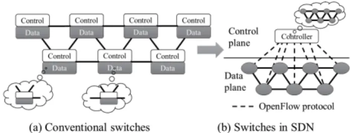
SDN is an architecture making the current application requirements possible. It is cost-effective, dynamic, and adaptable for today’s network. The SDN architecture sepa-rates the control and the data planes of a switch, putting the control plane into a separated centralized controller while remaining the data plane in the switch, as shown in Fig. 1. The controller acts as a brain to make a decision and instruct the switch how to process the incoming packets. The switch acts like a puppet, which only processes the incoming packets as the instructions from the controller without any decision. The centralized controller maintains a global view of the network. The network is able to be managed only by the con-troller. SDN allows the network administrator to dynamically configure, manage, and optimize the network using software regardless of the vendors.
OpenFlow is a protocol to realize the SDN architecture. It enables the controller to interact with the devices in the network, which defines messages, such as packet_in, packet_out, flow_mod, etc. Each OpenFlow instance on a switch is identified by a datapath ID. The data path presents
FIGURE 1. Comparison between conventional switch and switch in SDN architecture.
a flow table abstraction. A flow table consists of several flow entries. A flow entry is composed of a set of packet fields to match, which is called a rule, actions, and a counter. The structure of the flow entry is shown in Fig. 2. The rule indicates what kinds of the packet to be matched. If the packet matches the rule, the packet will be processed as the actions, which may be dropped, forwarded, and etc. After the packet is processed, the counter is increased. When a switch receives a packet that does not match any flow, the switch sends the packet to the controller. The controller makes a decision for the received packet. The decision can be dropping the packet or forwarding to the desired route. The controller can also send a flow_mod message to the switch to add a flow entry for the similar packets in the future.
FIGURE 2. Structure of flow entry.
III. CONVENTIONAL SCHEMES
In an SDN network, flow entries are needed to be installed in every corresponding switch along with a path between source and destination, once there is a request. The path may be automatically determined by the controller or manually determined by a network administrator. There are two flow configuration schemes to setup a connection. First, a per-manent flow (PF) scheme configures flow entries at initial before starting the network operation for all pairs of source and destination. The flow entries are permanently stored in the switches. Second, a non-permanent flow (NPF) scheme configures flow entries only if there is a request for a pair of source and destination.
A. PERMANENT FLOW SCHEME
The Permanent Flow (PF) scheme firstly determines the path between all source and destination pairs, and installs the flow
entries for those paths on all the switches in the network. The switch immediately forwards the packet to the desired egress port of the switch when a packet arrives at the switch without asking the controller. The advantage of this scheme is that the bandwidth required in the control plane is low because there is no inquiry about the path configuration. However, the TCAM memory in the switch may be full in this manner, as it needs to hold all possible flow entries for all pairs of source and destination. The switch may not be able to perform other functions, since the capacity of the TCAM memory is not enough to install flow entries for those functions.
The match field of the flow entry in the PF scheme only matches the destination IP address. The matched packet is sent to the output port defined in the action field. It should be noted that a network address can be used as the destination IP address, so that the number of flow entries can be reduced. Figure 3 shows an example of flow entries in the PF scheme. A topology with eight switches, from AtoH, used in the example is illustrated in Fig. 3(a). Flow table in each switch is shown in Fig. 3(b). Each flow entry matches a destination IP address. An output port is specified as an action for each flow entry. The number of permanent flows in each switch is five. The total number of permanent flows in the network becomes 40. There are three requests, which are (H1,H2), (H3,H4), and (H5,H6), in the example. The connection between hostsH1 andH2 is on the pathH1 ↔
C ↔A ↔ E ↔F ↔H2. The connection between hosts
H3 and H4 is on the path H3 ↔ B ↔ A ↔ E ↔ H4.
The connection between hosts H5 and H6 is on the path H5↔G↔H ↔H6. No configuration message is required in the scenario.
B. NON-PERMANENT FLOW SCHEME
In the non-permanent flow (NPF) scheme, each switch does not need a permanent flow entry. Initially, the number of flow entries associated with pairs of source and destination is zero. When a packet arrives at a switch, the switch sends a packet_into ask for the path configuration to the controller. Next, the controller computes the path between the source and the destination. The controller then sends configuration mes-sages containing the flow entries to configure the switches along the computed path. The IP address or network address is used in the matching entry of the flow entry. The output port is designated to direct the packet to a neighbor switch on the path. The advantage of the NPF scheme is that the TCAM memory can be used for other functions as a perma-nent flow entry is not required. However, the configuration messages may flood the control plane, especially in a high demand network such as a big data network.
Figure 4 shows flow configuration for the scenario in Fig. 3(a). Initially, there is no permanent flow entry in every switch. Therefore, the number of permanent flow entries is zero. Configuration messages that are sent from the controller to switches along the path include a destination IP address as match field and an output port as action field. One config-uration message is converted into a flow entry by a switch.
FIGURE 3. Flow entries for PF scheme.
Two flow entries are required for bidirectional transmis-sion in each switch for each pair of source and destina-tion. For example, the first two flow entries in switchAare
for H1 ↔ H2, and the last two flow entries are for
H3↔H4. The total number of configuration messages from the controller is 18 messages in this scenario.
IV. PROPOSED HYBRID PERMANENT FLOW SCHEME
The proposed scheme, called a hybrid permanent flow (HPF) scheme, adopts a concept of two MPLS tags, outer and inner tags, and employs both permanent and non-permanent flow entries. The permanent flow entries are permanently installed in every switch before starting a network operation. If a packet does not match any flow entry, the switch requests a configuration message, as a non-permanent flow entry, from the controller. A flow table is redesigned to support two MPLS tags. The number of configuration messages required
FIGURE 4. Example of flow entries for NPF scheme.
for a new request for a pair of source and destination is reduced, compared to the NPF scheme. In addition, the num-ber of permanent flow entries is reduced, compared to the PF scheme.
The HPF scheme divides switches in the network into mul-tiple groups. Each group is called a region. Each region has an individual region ID number, which is specified in the outer tag to indicate the destination region. A switch in the same region has an individual switch ID number, which is specified in the inner tag to indicate the destination switch. Switches are able to have the same switch ID number if they are in the different region. At least one of the switches in each region functions as an inter-region switch to connect the region with other regions. This switch is called an edge switch. A switch that is not connected to another region is called a non-edge switch. An outer MPLS tag guides packets from a source switch to an edge switch of the destination region. An inner MPLS tag guides the packets from the edge switch of the destination region to the destination switch. The outer and inner tags are statically predefined for each pair of source and destination. They are kept in the database of the controller. Figure 5 illustrates an operation of two tags utilization. Once a packet arrives at the switch S in the region RA and no any flow entry matches the packet, the switch S sends a packet_in to the controller. The controller obtains and an outer tag 501, an inner tag 102, and an output port from the database. It replies this information as a configuration message to the switchS. The switchS translates the con-figuration message into a flow entry to add two MPLS tags in the packet header. After the packet is forwarded to the output port of the switch S, the outer tag 501 is used to route the packets from the switchS to an edge switch in the regionRB. The edge switch of the region RB pop the outer tag 501, and forwards the packet to an output port using as an instruction of a permanent flow in the switch. The inner tag 102 is used to route the packets from the edge switch of the regionRBto the destination switch,D, in the same region. The switchDpop the inner tag 102 and forwards the packet to an
FIGURE 5. Concept of utilizing two MPLS tags.
output port. It should be noted that the same inner tag can be reused to route the packets in the different region.
Let us consider the network scalability using the MPLS tags. An MPLS packet format contains a 20-bit label value. This number supports up to 1,0488,576 pairs of source and destination. In the proposed HPF scheme, the maximum number of regions where the edge nodes are connected as a full mesh topology, for the worst case, is 3,239. The number of hosts in each region where they are connected as a full mesh topology is also 3,239. The HPF scheme supports more number of regions and hosts in other topologies.
Both non-permanent and permanent flow entries are used in the HPF scheme. For a new request, a non-permanent flow entry, obtained from the controller, is installed at only the first switch on the path. Match field of the non-permanent flow entry specifies the destination IP address. Action field pushes two MPLS tags and specifies an output port of the switch. A permanent flow entry is classified into three cate-gories. The first category is a flow entry for the local switch communication. The local switch communication refers to a communication between a switch and a host who has a direct link to the switch. Three permanent flow entries are needed for this category. (i) match field specifies IP address of a destination host, and action field indicates an output port. (ii) match field specifies its own switch ID number as an inner tag, and action field pop the inner tag and resubmit the flow to the same table. (iii) match field specifies its own region ID number as an outer tag, and action field pop the outer tag and resubmit the flow to the same table. The second category is a flow entry for the local region communication. Match field of this category specifies a switch ID number in the same region, excluding itself, as an inner tag. Action field indicates an output port. The third category is a flow entry for inter-region communication. Match field of this category specifies a region ID number as an outer tag. Action field indicates an output port.
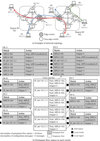
Figure 6 shows flow configurations of the HPF scheme for the scenario and topology in Fig. 6(a). Switches is dev-ided into two regions. The region 501 consists of switches A, B, C, and D. The region 502 consists of switches E,
F, G, and H. Switch ID number for A and E is 101,
for B and F is 102, for C and G is 103, and for D and H is 104. At initial, permanent flow entries are stored in every switch. Seven flow entries are contained in the edge
FIGURE 6. Flow entries of HPF scheme for example network.
switches A and E. Three flow entries forward packets to other switches in the local region. Three flow entries are used for packets where the destination is located in the local switch. One flow entry defines an output port for inter-region. 14 number of permanent flows are required at all the edge switches. Each non-edge switch consists of two flow entries. One matches an inner tag, and the other matches a destination IP address. The total number of permanent flow entries for all the non-edge switches is 12. Therefore, the number of permanent flows in the network is 26. Six configuration messages are required for three requests in this scenario. A. MATHEMATICAL FORMULATION
We formulate the optimization problem that minimizes the number of permanent flow entries in the hybrid permanent flow (HPF) scheme as an integer linear programming (ILP) problem to determine the set of switches in each region. The given inputs are the set of switchesS and the set of edges connecting themE. The preset routing paths are also given withrsdi equal to 1 if the path from sourcesto destinationd passes through nodei, and 0 otherwise. For the purpose of the formulation, we consider the maximum number of regions as given, and defineK = 1,· · · ,|K|as the set of possible regions.
The used decision variables are described as follows. Binary variablefikdefines the regionkin which switchiis in. It is set to 1 if switchiis in regionk, and 0 otherwise. Binary variablepjiidentifies the flow for local region communication. It is set to 1 if switchiregisters a flow destined to switchj within the same region, and 0 otherwise. Binary variablehki is defined to identify the inter-region flows. It is set to 1 if switch iregister a flow destined to a region k, which does not includei, and 0 otherwise. The edge routers are identified with the binary variableei, which is set to 1 if switchiis an edge switch, and 0 otherwise. Since each switch can be in only one region, it is not necessary to identify the region in which an edge switch is.
We define additional binary decision variables to formulate our problem with linear equations.xij is forced to 1 if there are traffic routed through switchiand destined to switchj. yji is set to 1 if switchesiandjare in the same region, and 0 otherwise.zki is set to 1 if switchiis not in region kand regionk is not empty.qk indicates non-empty regions. It is set to 1 if region k is occupied by at least a switch, and 0 otherwise.
To minimize the number of permanent flow entries, we minimize the sum of entries in all switches, which is constituted by (i) the sum of entries for local region commu-nications, (ii) the sum of entries for inter-region, and (iii) the sum of entries for local switch communications.
The sum of entries for local region communications over all switches is given by
X
i∈S
X
j∈S
pji. (1)
The sum of entries for inter-region over all switches is given by X i∈S X k∈K hki. (2)
The sum of entries for local switch over all switches is given by
X
i∈S
ei+v+u, (3)
where P
i∈Sei adds a flow entry to each edge switch to pop the outer tags destined within its region.vadds a flow entry to each edge switch to pop the inner tags destined within its switch, where v = |S|. u adds flow entries to each switch to forward the packet to its hosts, where u=H× |S|.
The overall number of permanent flow entries is given by
X i∈S X j∈S pji+X i∈S X k∈K hki +X i∈S ei+v+u. (4)
Since vanduare constant, therefore they do not affect the optimization result, we omit them in the ILP formulation of the HPF problem.
We formulate the HPF problem to minimize the number of permanent flow entries as follows:
min X i∈S X j∈S pji+X i∈S X k∈K hki +X i∈S ei (5a) Subject to X k∈K fik =1, ∀i∈S (5b) fsk+fdk−fik <2, ∀k∈K,s,d, i∈S, rsdi =1 (5c) fik+fjl ≤1+ei, ∀(i,j)∈E, k6=l ∈K (5d) xid ≥1, ∀s,d,i∈S (5e) fik+fjk ≤1+yij, ∀i, j∈S, k∈K (5f) X i∈S fik ≤(|S| +1)×qk, ∀k∈K (5g) qk−fik ≤zki, ∀i∈S, k∈K (5h) xij+yji≤1+pji, ∀(i,j)∈E (5i) xij+zki ≤1+hik, ∀(i,j)∈E, k∈K (5j) pji,xij,yji= {0,1}, ∀i, j∈S (5k) fik,hki,zki = {0,1}, ∀i∈S, k∈K (5l) ei= {0,1}, ∀i∈S (5m) qk = {0,1}, ∀k∈K. (5n)
The constraints to the HPF formulation are that (i) each switch is in one and only one region, (ii) switches that share the same region connect to each other through paths within the region, and (iii) switches which have at least a link leading to another region are edge switches. These constraints are for-mulated with Eqs. (5b), (5c) and (5d), respectively. Eq. (5b) ensures that a switchfik is set to 1 for each switchiin one and only one region k. Eq. (5c) ensures that if source and destination switchessanddshare a region, then any node in their path should be in the same region. Eq. (5c) forcesfik to 1 iffsk andfdk are equal to 1. Eq. (5d) identifies edges (i,j) that have one endiin a regionk (fik = 1 and the other end jon a another regionl (fjl = 1), and denotes switchias an edge switch by forcingeito 1. Eq. (5d) ensures that iffik =1 andfjl = 1 thenei = 1,eiis set to 0 otherwise due to the minimize objective function.
Eqs. (5e)-(5h) set the binary variable which are used to linearize our formulation. Eq. (5e) forcesxid to 1 if switch iis on a path to switchd. Eq. (5f) forcesyjito 1 if switchesi andjare both in regionk(fik =1 andfjk =1). Eq. (5g) forces qk to 1 if regionkincludes atleast a switch (Pi∈Sfik >0). Eq. (5h) forceszki to 1 if switchiis not in regionk(1−fik =1) and regionkis not empty (qk =1).
Eqs. (5i) and (5j) defines the decision variablespjiandhki. Eq. (5i) ensures thatpjiis forced to 1 if switchesiandjare in the same region (yji =1) and switchineeds to register flow for traffic destined to switchjpassing through it (xij = 1). Eq. (5j) ensures thathki is forced to 1 if switchiis needed to register flow for traffic destined to an outer regionkwhich is
not empty (xij=1 andzki =1).pjiandhki are minimized to 0 by objective function in the cases they are not forced to 1.
V. NUMBER OF FLOW ENTRIES AND CONFIGURATION MESSAGES ANALYSIS
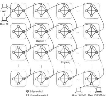
The purpose of this work is to reduce the number of per-manent flow entries and configuration messages required for source and destination pairs when there is a communication request between the source and the destination. Comparisons of those numbers of the PF, NPF, and HPF schemes are reported. A topology in Fig. 7 is used for the analysis since it is easy to conduct the analytical study. The topology consists ofR×Rregions connected as a grid topology. In each region, S switches are connected as a mesh topology. Each switch connects toHhosts.
FIGURE 7. Network topology for analysis.
A. PF SCHEME ANALYSIS
The total number of flow entries required for the network is the sum of the flow entries required for all pairs of source and destination. Let TnPF,TePF, andTrPF be the number of permanent flow entries per non-edge switch, edge switch, and region, respectively, in the PF scheme. LetFPF be the total number of required permanent flow entries in the network for the PF scheme. All of them are expressed by,
FPF =R2TrPF (6)
TrPF =TePF+TnPF(S−1) (7)
TePF =(R2−1)+(S−1)+H (8)
TnPF =TePF. (9)
With the PF scheme, no configuration message is required, regardless of the number of requests corresponding to the pair of source and destination. Therefore, the number of configuration messages in the PF scheme,MPF, is zero.
B. NPF SCHEME ANALYSIS
In the NPF scheme, the number of permanent flow entries in the network is zero (FNPF =0) since permanent flow entries are not required. However, the controller sends configuration messages to install flow entries in the corresponding switches along the path for the request from the source to the destina-tion. The number of configuration messages in this scheme depends on the number of intermediate switches along the path. We assume the shortest path between the source and the destination in this analysis. Letiandjbe region ID number of a source switch and a destination switch, respectively. Letmx be a position of regionx on row of matrixR×R. Letnxbe a position of regionxon column of matrixR×R. Let dijqbe a distance between regioniandjfor requestq. Letdsiq be a distance between a source switch and the edge switch of the source region for requestq. Letdjdq be a distance between the edge switch of a destination region and a destination switch for requestq. LetQbe the amount of requests.qis request index, where 1 ≤ q ≤ Q. The number of required configuration messages in the NPF scheme, MNPF, for all pairs of source and destination can be found by,
MNPF = Q X q=1 (dsiq+dijq+djdq +1) (10) dijq= |mq j −m q i| + |n q j −n q i| (11) mx = d x de (12) nx =(x−1) modR+1 (13) dsiq = (
0 if source switch is edge switch
1 otherwise (14)
djdq = (
0 if destination switch is edge switch
1 otherwise. (15)
C. HPF SCHEME ANALYSIS
The total number or permanent flow entries for the HPF scheme,FHPF, in the network with the topology in Fig. 7 is obtained by,
FHPF =R2TrHPF (16)
TrHPF =TeHPF+TnHPF(S−1) (17)
TeHPF =R2+S+H (18)
TnHPF =H+1, (19)
whereTnHPF,TeHPF, andTrHPFoare the number of flow entries of the HPF scheme per non-edge switch, edge switch, and region, respectively.
Only one configuration message is required for each pair of source and destination. The configuration message config-ures a flow entry at only the source switch. The total number of configuration messages forQrequests isQ,MHPF =Q.
VI. PERFORMANCE EVALUATION
The performance of the HPF scheme is evaluated using both ILP and analysis. First, we use the ILP formulation to
determine the set of switches in each region. Second, perfor-mance of the proposed HPF is compared with NPF and PF schemes by the analysis.
A. DETERMINATION OF REGION USING ILP
The topologies in Figs. 8(a) and (b) consist of 14 and 16 nodes, respectively, are used to evaluate the performance. A given route between each pair of source and destination is determined by the shortest path. In the NSF topology, three regions are determined from the ILP, as shown with the red lines in Figs. 8(a). The total number of permanent flow entries is 106 flows. In the sample topology, four regions are deter-mined from the ILP, as shown by the red lines in Figs. 8(b). The total number of permanent flow entries is 60 flows.
FIGURE 8. Topologies used for ILP formulation.
B. ANALYSIS OF THE NUMBER OF PERMANENT FLOWS The performance of the HPF scheme is compared with that of the PF and NPF schemes. A network topology as in Fig. 7 is considered. ParametersR=S =H=4 are always assumed, unless otherwise stated.
We firstly evaluate the performance of all schemes in terms of the total number of permanent flows, which is counted after initial flow configuration is completed. It should be noted that the total number of permanent flows in the network of the NPF scheme is zero for everyH,R, andS. Therefore, only the performance of the PF and HPF schemes will be explained.
Figure 9 shows the dependency ofRin term of the number of permanent flows in the network. The number of permanent flows of the HPF scheme is less than that of the PF scheme. In the case ofR=2, the HPF scheme has 35% of the number of permanent flows lower than the PF scheme. The number of permanent flows in the HPF scheme is reduced up to 70% whenR=8.
The dependency ofS in term of the number of permanent flows is shown in Fig. 10. The number of permanent flows of the HPF scheme is lower than that of the PF scheme. It increases with the growth of S. In the case of S = 2, the number of permanent flows of the HPF scheme is 35% lower than that of the PF scheme. It is reduced by 70%, approximately, whenS =8. The result indicates that lesser than 50% of the number of permanent flows is achieved when S ≥3.
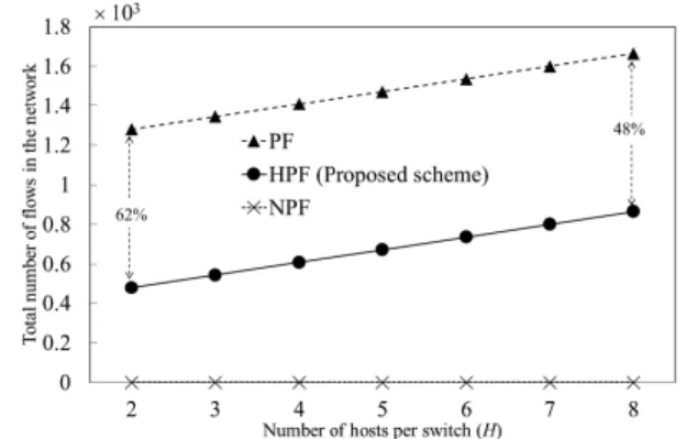
Figure 11 shows the dependency of H in term of the number of permanent flows in the network. The number of permanent flows of the PF scheme is higher than that of the
FIGURE 9. Dependency of dimension of regions in term of total number of flows (S=4,H=4).
FIGURE 10. Dependency of number of switches per region in term of total number of flows (R=4,H=4).
FIGURE 11. Dependency of number of hosts per switch in term of total number of flows (R=4,S=4).
proposed HPF scheme. The number of permanent flows of both PF and HPF schemes increases withH. In the case of H =2, the number of permanent flows of the HPF scheme is 62% lower than that of the PF scheme. It is reduced by 48%, approximately, whenH=8.
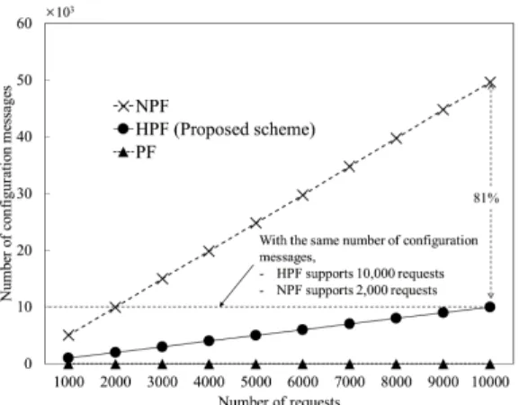
Second, we investigate the number of configuration mes-sages when there are requests for source and destination pairs. 10,000 pairs of source and destination are randomly generated for the simulation. The number of configuration messages is counted every 1,000 pairs for each scheme. It should be noted that the performance of the PF scheme
FIGURE 12. Dependency of number of requests in term of number of configuration messages.
FIGURE 13. Topology and requests for experiment.
in this investigation will not be discussed because no con-figuratioin message is needed in the PF scheme. Figure 12 shows the dependency of the number of requests in term of the number of configuration messages. The number of config-uration messages of the HPF scheme is 81% lower than that of the NPF scheme. The result shows that the HPF scheme maintains more number of requests than the NPF scheme in case of the same number of configuration messages. For instance, the NPF scheme maintains only 2,000 requests, while the proposed HPF scheme maintains 10,000 requests with the same number of configuration messages.
VII. DEMONSTRATION
The implemented HPF scheme is demonstrated via Science Information Network 5 (SINET5) [15], [16], which is pro-vided by the national institute of informatics (NII), across Japan to confirm the functionality of the scheme. Seven virtual machines (VMs) are installed in four locations [17]. The information of VMs for the demonstration is listed in Table 1.
All VMs are connected as a topology in Fig. 13. The SDN controller is implemented using RYU. Every switch is
FIGURE 14. Database structure.
FIGURE 15. Permanent flows in corresponding switches.
FIGURE 16. Packet in from HOST_Tokyo to HOST_Osaka.
TABLE 1.Information of VMs for demonstration.
connected to the controller. In the demonstration, the data of source IP, destination IP, inner tag, outer tag, and output port of the related scenario is stored in the controller database in a table MPLS_tag, as shown in Fig. 14. Two connections, HOST_Hokkaido↔HOST_Osaka for connection between different regions and HOST_Tokyo ↔ HOST_Osaka for connection within the same region, are demonstrated. An outer tag is not required for the connection of
FIGURE 17. Configuration message for HOST_Tokyo to HOST_Osaka.
FIGURE 18. Ping request packets from HOST_Tokyo to HOST_Osaka.
HOST_Tokyo↔HOST_Osaka, since the souorce and desti-nation are in the same region. All connections are tested using a ping command. Permanent flows are added, as in Fig. 15, when the controller starts.
FIGURE 19. Packet in from HOST_Hokkaido to HOST_Osaka.
FIGURE 20. Configuration message for HOST_Hokkaidoo to HOST_Osaka.
A. DEMONSTRATION RESULTS
We firstly confirm the connection between HOST_Tokyo and HOST_Osaka, where they are located in the same region. A ping request packet is sent from HOST_Tokyo to HOST_Osaka. After the packet from HOST_Tokyo arrives at
OVS_Tokyo, OVS_Tokyo asks the controller how to proceed this packet, as a packet_in in Fig. 16. The controller obtains the information of the MPLS tag and the output port from the database, and replies a flow_mod entry, as a configuration message in Fig. 17, to add a flow at OVS_Tokyo. This flow is called a non-permanent flow. This non-permanent flow will be removed from OVS_Tokyo after the flow is idled for a given idle timeout. In this demonstration, we omit the configuration of idle timeout. An MPLS tag with label 102 is push to the ping request packet at OVS_Tokyo, and it is pop at OVS_Osaka before forwarding to HOST_Osaka, as ping packets shown in Fig. 18.
Secondly, we confirm the connection between HOST_Hokkaido and HOST_Osaka via OVS_Tokyo, where both hosts are located in a different region. A ping request is sent from HOST_Hokkaido to OVS_Hokkaido. OVS_Hokkaido asks an instruction from the controller, as packet_in in Fig. 19. The controller replies a configuration message to OVS_Hokkaido, as shown in Fig. 20. The inner tag 102 and outer tag 502 are added into the packet at OVS_Hokkaido. The packet then travels to the destination region 502, where it arrives at OVS_Tokyo. OVS_Tokyo matches the packet with a permanent flow, and pop the outer tag 502 before forwarding it to a desired output port. The inner tag 102 is pop at OVS_Osaka. Finally, the packet arrives at HOST_Osaka.
It should be noted that ping reply packets for both con-nections perform in the same way as ping requests. This demonstration confirms that the operation in the proposed HPF is correct.
VIII. CONCLUSIONS
This paper proposed a scheme to reduce both the number of permanent flow entries and the number of configuration messages from the controller, called a hybrid permanent flow (HPF) scheme, in SDN. In this scheme, switches in the network are divided into several regions. Two MPLS tags, outer and inner tags, are adopted for a packet routing. The outer tag navigates a packet from a source switch to an edge switch in its destination region. The inner tag navigates the packet from the edge switch to the destination switch in the local region. A mathematical formulation to determine a set of switches in each region so that the total number of permanent flow entries in the network is minimized was introduced. The NSF topology and a sample topology was used as the examples. In the NSF topology, the switches are grouped into three regions. The analysis of the number of flow entries for a sample topology was introduced. The per-formance of the HPF scheme was analyzed. Results from the analysis indicated that 70% of the number of permanent flow entries and 80% of the number of configuration messages are reduced, compared to the conventional schemes. These reductions require a lower bandwidth in the control plane, a lower process of CPU in the controller, and a smaller TCAM memory size in each switch. We demonstrated the proposed scheme via Japanese Science Information Network 5.
Acknowledgment
This paper was presented at the IEEE Conference on Stan-dards for Communications and Networking (CSCN2016) [1].
REFERENCES
[1] N. Kitsuwan and E. Oki, ‘‘Analysis of flows reduction scheme by adopting two MPLS tags in software-defined network,’’ inProc. IEEE Conf. Stan-dards Commun. Netw. (CSCN), Nov. 2016, pp. 1–6.
[2] Facebook Q4 2015 Results. Accessed on Mar. 2016. [Online]. Available: http://investor.fb.com/results.cfm
[3] Facebook’s Top Open Data Problems. Accessed on Mar. 2016. [Online]. Available: https://research.facebook.com/ blog/facebook-s-top-open-data-problems/
[4] Z. Han, M. Bennis, D. Wang, T. Kwon, and S. Cui, ‘‘Special issue on big data networking-challenges and applications,’’IEEE/OSA J. Commun. Netw., vol. 17, no. 6, pp. 545–548, Jun. 2015.
[5] H. M. Chen, R. Schütz, R. Kazman, and F. Matthes, ‘‘Amazon in the air: Innovating with big data at Lufthansa,’’ inProc. 49th Hawaii Int. Conf. Syst. Sci. (HICSS), Jan. 2016, pp. 5096–5105.
[6] N. Mishra, C. C. Lin, and H. T. Chang, ‘‘A cognitive oriented framework for IoT big-data management prospective,’’ inProc. IEEE Int. Conf. Commun. Problem-Solving (ICCP), Dec. 2014, pp. 124–127.
[7] H. Hu, Y. Wen, Y. Gao, T. S. Chua, and X. Li, ‘‘Toward an SDN-enabled big data platform for social TV analytics,’’IEEE Netw., vol. 29, no. 5, pp. 43–49, May 2015.
[8] N. McKeown, ‘‘Software-defined networking,’’ inProc. INFOCOM, 2009, pp. 30–32.
[9] (Jun. 2012).OpenFlow Switch Specification Version 1.3.0. [Online]. Avail-able: https://www.opennetworking.org/
[10] Y. Cui, J. Song, M. Li, Q. Ren, Y. Zhang, and X. Cai, ‘‘SDN-based big data caching in ISP networks,’’IEEE Trans. Big Data. [Online]. Available: http://ieeexplore.ieee.org/document/7817877/
[11] L. W. Cheng and S. Y. Wang, ‘‘Application-aware SDN routing for big data networking,’’ inProc. IEEE Global Commun. Conf. (GLOBECOM), Dec. 2015, pp. 1–6.
[12] P. Qin, B. Dai, B. Huang, and G. Xu, ‘‘Bandwidth-aware scheduling with SDN in Hadoop: A new trend for big data,’’IEEE Syst. J.[Online]. Available: http://ieeexplore.ieee.org/document/7332913/
[13] L. Cui, F. R. Yu, and Q. Yan, ‘‘When big data meets software-defined networking: SDN for big data and big data for SDN,’’IEEE Netw., vol. 30, no. 1, pp. 58–65, Jan. 2016.
[14] N. Kitsuwan, S. McGettrick, F. Slyne, D. B. Payne, and M. Ruffini, ‘‘Independent transient plane design for protection in OpenFlow-based networks,’’IEEE/OSA J. Optic. Commun. Netw., vol. 7, no. 4, pp. 264–275, Apr. 2015.
[15] (Oct. 2016). Science Information NETwork 5. [Online]. Available: https://www.sinet.ad.jp/en/top-en
[16] (Oct. 2016). National Institute of Informatics. [Online]. Available: http://www.nii.ac.jp/en/
[17] T. Kurimotoet al., ‘‘A fully meshed backbone network for data-intensive sciences and SDN services,’’ inProc. 8th Int. Conf. Ubiquitous Future Netw. (ICUFN), Jul. 2016, pp. 909–911.
NATTAPONG KITSUWANreceived the B.E. and M.E. degrees in electrical engineering (telecom-munication) from King Mongkut’s Institute of Technology, Mahanakorn University of Technol-ogy, Ladkrabang, Thailand, in 2000 and 2004, respectively, and the Ph.D. degree in infor-mation and communication engineering from University of Electro-Communications, Tokyo, Japan, in 2011. From 2002 to 2003, he was an Exchange Student with University of Electro-Communications, where he performed research regarding optical packet switching. From 2003 to 2005, he was with ROHM Integrated Semicon-ductor, Thailand, as an Information System Expert. He was a Post-Doctoral Researcher with University of Electro-Communications from 2011 to 2013. He was a Researcher with the Telecommunications Research Centre, Trinity College, Dublin, Ireland, from 2013 to 2015. He is currently an Assistant Professor with University of Electro-Communications. His research focuses on optical network technologies, routing protocols, and software-defined networks.
SEYDOU BAreceived the M.E. and Ph.D. degrees in information and communication engineer-ing from University of Electro-Communications, Tokyo, Japan, in 2014 and 2017, respectively. He is with the NEC-AIST AI Cooperative Research Laboratory, National Institute of Advanced Indus-trial Science and Technology. His research inter-ests include artificial intelligence, reinforcement learning, elastic optical networks, and software defined networks.
EIJI OKI (F’13) received the B.E. and M.E. degrees in instrumentation engineering and the Ph.D. degree in electrical engineering from Keio University, Yokohama, Japan, in 1991, 1993, and 1999, respectively. In 1993, he joined Nippon Tele-graph and Telephone (NTT) Corporation Commu-nication Switching Laboratories, Tokyo, Japan. He has been researching network design and control, traffic-control methods, and high-speed switching systems. From 2000 to 2001, he was a Visiting Scholar with Polytechnic Institute of New York University, Brooklyn, NY, USA, where he was involved in designing terabit switch/router systems. He was engaged in researching and developing high-speed optical IP back-bone networks with NTT Laboratories. He was with University of Electro-Communications, Tokyo, from 2008 to 2017. He joined Kyoto University, Japan, in 2017, where he is currently a Professor. He has been active in the standardization of the path computation element and GMPLS in the IETF. He has authored over ten IETF RFCs. He has authored/co-authored four books:Broadband Packet Switching Technologies(New York: Wiley, 2001),GMPLS Technologies(Boca Raton, FL: CRC Press, 2005),Advanced Internet Protocols, Services, and Applications(New York: Wiley, 2012), and
Linear Programming and Algorithms for Communication Networks(Boca Raton, FL: CRC Press, 2012). He was a recipient of several prestigious awards, including the 1998 Switching System Research Award and the 1999 Excellent Paper Award presented by IEICE, the 2001 Asia-Pacific Outstanding Young Researcher Award presented by the IEEE Commu-nications Society for his contributions to broadband network, ATM, and optical IP technologies, the 2010 Telecom System Technology Prize by the Telecommunications Advanced Foundation, the IEEE HPSR 2012 Outstand-ing Paper Award, and the IEEE HPSR 2014 Best Paper Award Finalist, First Runner Up.
TAKASHI KURIMOTO received the B.E. and M.E. degrees in applied physics from Tokyo Insti-tute of Technology, Japan, in 1992 and 1994, respectively, and the Ph.D. degree from Keio Uni-versity in 2012. He was with NTT Network Ser-vice Systems Laboratories and the NTT East Plant Planning Department from 1994 to 2014. He has been involved in researching the switching tech-nology for high-speed computer networks and deployment of the next-generation network. He moved to NII in 2015, where he is currently involved in the design and implementation of the Science Information Network. He received the IEICE Switching System Research Award in 1996.
SHIGEO URUSHIDANI received the B.E. and M.E. degrees from Kobe University in 1983 and 1985, respectively, and the Ph.D. degree from The University of Tokyo in 2002. He was with NTT from 1985 to 2006, where he was involved in the research and development of ATM, AIN, IP/MPLS, and optical switching systems. He moved to National Institute of Informatics (NII), Japan, in 2006, where he is currently involved in the design and implementation of the Science Information Network, and in the Research and Development on network and system architecture for ultra-high-speed green networks. He is currently a Professor and the Director of the Research Center for Academic Networks, NII. He is also the Director of the Cyber Science Infrastructure Development Department, NII.