University
of
Cape
Town
Carrier Grade Resilience in Geographically
Distributed Software Defined Networks
John Arundel Lewis
Supervisor:
Neco Ventura
Dissertation submitted to the Department of Electrical Engineering in
fulfilment of the requirements for the Master of Science in Electrical
Engineering degree at the University of Cape Town
December 2016
The copyright of this thesis vests in the author. No
quotation from it or information derived from it is to be
published without full acknowledgement of the source.
The thesis is to be used for private study or
non-commercial research purposes only.
Published by the University of Cape Town (UCT) in terms
of the non-exclusive license granted to UCT by the author.
iii
Declaration
I know the meaning of plagiarism and declare that all the work in the document, save for that which is properly acknowledged, is my own. This dissertation has been submitted to the Turnitin module (or equivalent similarity and originality checking software) and I confirm that my supervisor has seen my report and any concerns revealed by such have been resolved with my supervisor.
_________________________________
John Arundel Lewis
iv
Supervisor’s Declaration
As the candidate’s supervisor, I have approved this dissertation for submission.
_________________________________
Neco Ventura
v
Acknowledgements
I would like to thank the following people for their help and support throughout this project: My parents, for all their support, encouragement, and many hours of proofreading.
Neco Ventura, for his excellent supervision and guidance during the project. Nyasha Mukudu, for the helpful technical discussions.
Niels van Adrichem, for sharing an early copy of ‘Computing backup rules in SDN’ and the associated source code.
vi
Abstract
The Internet is a fundamental infrastructure in modern life, supporting many different communication services. One of the most critical properties of the Internet is its ability to recover from failures, such as link or equipment failure. The goal of network resilience heavily influenced the design of the Internet, leading to the use of distributed routing protocols.
While distributed algorithms largely solve the issue of network resilience, other concerns remain. A significant concern is network management, as it is a complex and error-prone process. In addition, network control logic is tightly integrated into the forwarding devices, making it difficult to upgrade the logic to introduce new features. Finally, the lack of a common control platform requires new network functions to provide their own solutions to common, but challenging, issues related to operating in a distributed environment.
A new network architecture, software-defined networking (SDN), aims to alleviate many of these network challenges by introducing useful abstractions into the control plane. In an SDN architecture, control functions are implemented as network applications, and run in a logically centralized network operating system (NOS). The NOS provides the applications with abstractions for common functions, such as network discovery, installation of forwarding behaviour, and state distribution. Network management can be handled programmatically instead of manually, and new features can be introduced by simply updating or adding a control application in the NOS.
Given proper design, an SDN architecture could improve the performance of reactive approaches to restoring traffic after a network failure. However, it has been shown in this dissertation that a reactive approach to traffic restoration will not meet the requirements of carrier grade networks, which require that traffic is redirected onto a back-up route less than 50 ms after the failure is detected. To achieve 50 ms recovery, a proactive approach must be used, where back-up rules are calculated and installed before a failure occurs. Several different protocols implement this proactive approach in traditional networks, and some work has also been done in the SDN space.
However, current SDN solutions for fast recovery are not necessarily suitable for a carrier grade environment. This dissertation proposes a new failure recovery strategy for SDN, based on existing protocols used in traditional carrier grade networks. The use of segment routing allows for back-up routes to be encoded into the packet header when a failure occurs, without needing to inform other switches of the failure. Back-up routes follow the post-convergence
vii
path, meaning that they will not violate traffic engineering constraints on the network. An MPLS (multiprotocol label switching) data plane is used to ensure compatibility with current carrier networks, as MPLS is currently a common protocol in carrier networks.
The proposed solution was implemented as a network application, on top of an open-source network operating system. A geographically distributed network testbed was used to verify the suitability for a geographically distributed carrier network. Proof of concept tests showed that the proposed solution provides complete protection for any single link, link aggregate or node failure in the network. In addition, communication latencies in the network do not influence the restoration time, as they do in reactive approaches. Finally, analysis of the back-up path metrics, such as back-up path lengths and number of labels required, showed that the application installed efficient back-up paths.
viii
Table of
Contents
Chapter 1 ... 1 Introduction ... 1 1.1. Research Motivation ... 3 1.1.1. Problem Definition... 6 1.1.2. Research Questions ... 7 1.2. Dissertation Objectives ... 81.3. Scope and Limitations ... 8
1.4. Dissertation Outline ... 9
Chapter 2 ... 10
Background and Literature Review ... 10
2.1. Software-Defined Networking Architecture ... 10
2.1.1. Data forwarding elements ... 11
2.1.2. Southbound API ... 12
2.1.3. Network Operating System ... 13
2.1.4. Northbound API ... 14
2.1.5. Network applications ... 15
2.2. Carrier Network Routing Protocols ... 15
2.2.1. Multiprotocol Label Switching ... 16
2.2.2. Segment Routing ... 16
2.3. Data Plane Failure Recovery ... 18
2.3.1. Reactive Approaches ... 18
2.3.2. Proactive Approaches ... 21
Data plane configuration ... 21
Back-up rule calculation ... 23
2.4. Chapter Discussions ... 24
ix
Requirements and Design of a Carrier Grade SDN FRR Solution ... 25
3.1. Carrier Core Network ... 25
3.1.1. Carrier Network Architecture ... 25
3.1.2. Core Network Topology ... 26
3.1.3. Core Network Requirements... 27
3.2. Fast Reroute Requirements and Design Considerations... 28
3.3. Design of the Proposed Fast Reroute Algorithm ... 28
3.4. Functional System Architecture ... 31
3.5. Chapter Discussions ... 33
Chapter 4 ... 34
Implementation of a Carrier Grade SDN FRR Solution and Evaluation Platform ... 34
4.1. Network Layer ... 34
4.1.1. OpenFlow Switch... 34
4.1.2. Network Environment ... 35
Mininet ... 35
GENI ... 36
4.2. Network Operating System ... 36
4.3. Network Applications ... 37
4.3.1. Reactive Application ... 37
4.3.2. Proactive FRR Application ... 39
Link and Node Discovery ... 40
Primary forwarding matrix ... 40
Back-up forwarding matrix ... 41
Back-up path label stack ... 41
Forwarding flow rules and groups ... 43
Host learning and edge rule installation ... 47
x
4.4.1. Mininet Topologies ... 48
4.4.2. GENI Topologies ... 52
4.5. Performance Metrics and Evaluation Tools ... 54
4.5.1. Failure Generation ... 54
4.5.2. Response Time ... 55
4.5.3. Connectivity ... 55
4.5.4. Back-up Path Length... 56
4.6. Chapter Discussions ... 57
Chapter 5 ... 58
Results and Discussion ... 58
5.1. Reactive Approach ... 58
5.1.1. Effect of Computational Resources on Response Time ... 59
5.1.2. Effect of the Number of Installed Intents on Response Time ... 60
5.1.3. Communication Latencies in a Geographically Distributed Testbed ... 62
5.2. Proposed FRR Approach ... 63
5.2.1. Path Verification ... 64
5.2.2. Connectivity ... 66
5.2.3. Path Lengths and Label Stacks ... 66
5.2.4. Functionality Verification in a Distributed Testbed ... 69
5.3. Chapter Discussions ... 70
Chapter 6 ... 72
Conclusions and Recommendations ... 72
6.1. Summary ... 72
6.2. Conclusions ... 73
6.3. Recommendations ... 73
References ... 76
xi
Modification to Open vSwitch to Support Additional MPLS Labels ... 81 Appendix B ... 82 Host Specific Labels ... 82
xii
Abbreviations
API Application programming interfaceARP Address resolution protocol
BFD Bidirectional forwarding detection
CPE Customer premises equipment
EC2 Elastic Cloud Compute
ECMP Equal-cost multipath
FIB Forwarding information base
FRR Fast reroute
GENI Global Environment for Network Innovations
GiB Gibibyte
HTTP Hypertext Transfer Protocol
IP Internet Protocol
ITU International Telecommunications Union
km Kilometer
LACP Link aggregation control protocol
LFA Loop-free alternate
LOS Loss-of-signal
LSP Label-switched path
MPLS Multiprotocol Label Switching
ms Millisecond
NOS Network operating system
OVS Open Virtual Switch
P Provider
PE Provider edge
PHP Penultimate hop popping
PLR Point of local repair
xiii
QoS Quality of service
REST Representational state transfer RLFA Remote loop-free alternate
RSVP-TE Resource Reservation Protocol – Traffic Engineering
RTT Round trip time
SA South Africa
SDN Software defined networking
SLA Service level agreement
SONET Synchronous Optical Networking
SR Segment routing
US United States of America
1
Chapter 1
Introduction
The Internet is a fundamental infrastructure for modern life, with over 3.6 billion users [1]. While the Internet has disrupted many sectors such as education, communication, and research, it has created entirely new sectors as well. Many services and applications now rely on the Internet’s robustness to meet business goals, and users expect a consistent level of service. Therefore, one of the most important characteristics of the Internet is its ability to maintain performance regardless of equipment failures in the network.
This ability to recover from failures, or resilience, has been a fundamental goal since the inception of the Internet, and significantly influenced its design. The distributed nature of the Internet’s routing protocols contributed significantly to its resilience [2], since distribution means that there is no single point of failure. In addition, distributed systems generally scale better than centralized systems which may experience performance bottlenecks.
While distribution is an enabler of resilience, it significantly complicates management and configuration of the network. Many different devices must be individually configured, requiring an operator to use many different vendor specific and low-level languages. This makes device configuration and network management complex and error-prone [2]. As the network scales, the management becomes more complex [3]. The result is a system where innovation is slow, management and operational costs are high, and errors are difficult to trace and fix.
Distributed algorithms also hinder the flexibility of the network, since it is hard to implement new features in a large set of devices. Firmware upgrades are not always possible, and hardware upgrades are prohibitively expensive to perform regularly. In order to introduce new features into the network, such as load balancing, firewalls, and traffic engineering, operators rely heavily on specialized networking equipment, called middleboxes, to provide these functions [2]. Middleboxes are devices that transform, inspect, filter, or otherwise manipulate network traffic. This increases both the capital and operational cost of the network, as well as further complicating network management.
Network inflexibility impacts not only the network cost, but also revenue. While the cost per bit is not necessarily decreasing as the network scales [3], consumers increasingly want more
2
data at a lower cost. To remain profitable and attract customers, operators must therefore either make their networks more efficient, lowering the cost per bit, or they must look for additional revenue streams. A more flexible network could provide these additional revenue streams by enabling services that are currently challenging, such as dynamic bandwidth allocation and time-of-day access control.
These issues stem, in large part, from the lack of a common control platform or network-wide management abstraction [4] [5]. The control plane in traditional networks is tightly integrated into the forwarding devices, and its distribution model is fixed by the network topology. The data plane forwards traffic based on the local forwarding model calculated by the control plane. However, the process to calculate the local forwarding model relies on information from other nodes, and thus the control plane must perform non-local calculations. Finally, the management plane provides operational access and monitoring [6]. All three of these planes are contained within a traditional router, as shown in Figure 1 below.
Due to the lack of a common control platform, new control functions must provide their own implementations of various common functions, such as network discovery and state distribution. This introduces a significant barrier to innovation, as the new functions must first solve the hard, low-level problem of designing a distributed protocol [4].
A new networking architecture, software-defined networking (SDN), has been proposed to alleviate some of these issues by introducing useful abstractions into the network. In an SDN paradigm, control functions run as applications within a logically centralized network operating system (NOS). Another common term for the NOS is ‘SDN controller’, and these terms will be used interchangeably. The NOS provides the applications with a global network view, as well as a programmatic interface to allow direct control of the network’s forwarding devices [6]. This architecture decouples the control plane from the data plane, allowing the switches to become simpler devices that only forward traffic and do not contain a control plane, and allowing the NOS to run on general purpose servers [4].
Control Plane
Data Plane
Management Plane
3
In addition, the control plane’s distribution is no longer fixed by the underlying network architecture, and well-established cloud computing techniques can be used to run the NOS on a distributed set of servers, enabling reliability and scalability [4]. While the control plane will still be distributed, state distribution is now the responsibility of the NOS, and not the control functions. State distribution primitives only need to be implemented once in the NOS, and then made available to the network applications [4]. Figure 2 shows a high-level view of this architecture, as laid out in a recommendation from the International Telecommunications Union (ITU) [7].
1.1.
Research Motivation
The main aim of SDN is to introduce useful abstractions into the control plane, particularly by providing a global network view and a standardized, programmatic interface to the network devices. To accomplish this, the control plane is decoupled from the forwarding devices, which also allows the control plane software to be updated independently of the network hardware.
Although this approach has many well-documented benefits, and the field is maturing rapidly, there are still a number of open challenges that must be solved before adoption becomes more widespread [2]. Some of these challenges are introduced by the SDN architecture, while others are present in current networks.
Data transport and processing Control support Abstraction Orchestration Application support Application Application Mult i-la y er m ana g em ent func ti ons SDN control layer Resource layer Application layer Application-control interface Resource-control interface
4
One of these open areas is network resilience. As already mentioned, resilience is a key property of the Internet, and computer networks in general. With the control plane removed from the switches, they can no longer independently recalculate the forwarding information base (FIB) required to correctly forward traffic. This could limit the ability of the switches to handle failures in the data plane (e.g. link or node failure), or failures in the controller-switch communication link. Furthermore, a centralized NOS could introduce a single point of failure, that could disable the entire network if it were to fail.
Many of these concerns have been already addressed in practical SDN implementations. For instance, controller-switch link failures can be dealt with by routing control traffic through neighbouring switches that still have a connection to the NOS [8]. Reliability in the control plane can be achieved through replication or redundancy, using multiple active instances of the NOS or back up instances [9]. Switches can connect to multiple instances of the NOS (using only one as the active controller) to further mitigate against controller failure and controller-switch link failure.
Data plane failures, however, are still a challenging area of concern. This is true in traditional networks, but SDN introduces some additional concerns since the switches do not contain control logic.
Typically, traditional networks respond to failures by propagating the topology update through the network, and recalculating the FIB at each node based on the new topology. This process could take a few milliseconds, or hundreds of seconds, depending on the network and the switches [10]. During this process, traffic may be lost, and transient micro-loops often form. Since the Internet is a best-effort transport network, these failures are largely hidden from the users by fault handling mechanisms at the application level which retransmit the lost data [10].
A similar reactive approach is typically implemented in SDN, where switches notify the controller of the failure, and the controller calculates and installs a new FIB at the affected switches. This approach is less likely to form transient loops, but there are concerns that the control plane could form a bottleneck during a topology change.
There are many scenarios, however, where this reactive approach to network failures is insufficient. In carrier-grade networks, operators typically expect traffic to be redirected onto a back-up path within 50 ms of a failure being detected [11]. This requirement originates from Synchronous Optical Networking (SONET), an optical transport protocol that guarantees sub 50 ms failover times when back-up fibre links are available [10]. Since SONET is a physical
5
layer protocol, efforts have been made to provide similar failover times that are independent of the underlying physical layer. Various Fast Reroute (FRR) protocols have been developed to achieve this, including Internet Protocol (IP) FRR and Multiprotocol Label Switching (MPLS) FRR [10].
To implement FRR in a traditional network, a node must pre-calculate a set of back-up forwarding actions to take if a node or link fails. A simple approach is to pre-compute a back-up next hop that will not cause a loop to form. This next-hop is called a loop-free alternate (LFA) [12]. This approach does not require any co-ordination with other nodes, as it relies on the pre-failure network paths. However, the presence of a suitable LFA depends heavily on the topology, and protection cannot always be guaranteed.
To demonstrate the concept of LFAs, Figure 3a shows a hypothetical network topology where a suitable LFA is present. The numbers next to the links represent the weight of the link used in the routing algorithm, which chooses the path with the least combined link weight. The primary network path between the source S and the destination D uses node A, and is represented by solid green lines. To protect against a failure of link S-A, node B can be used as a backup next-hop. The pre-failure network path from B to D will use link B-D, and traffic will not loop. This backup path is represented by dashed green lines. If link S-A fails, node S can repair the path to D by rerouting traffic away from the failure, onto link S-B. This is a local repair action; hence node S is called the point of local repair (PLR).
However, if the link weight of B-D is increased to 10, as shown in Figure 3b, node B is no longer a suitable LFA. The primary path from B to D is via node S and node A, which means that if node S redirects traffic to B, it will be returned. Therefore, if link S-A fails and node S
Figure 3 - Network topology with a suitable LFA (a) and without (b) [14] S D A B 2 2 4 2 S D A B 2 2 10 2 (a) (b)
6
attempts to repair the path by redirecting traffic to B, a loop would form, represented by dashed red lines.
To increase coverage (the percentage of failures the FRR scheme can protect against), the LFA method can be extended to use remote LFAs (RLFAs). A remote LFA is a node that will correctly forward the traffic to the destination using pre-failure network paths that do not traverse the failure, without causing any loops in the network. When a failure occurs, the PLR will forward traffic directly to an RLFA, generally using some type of tunnelling technique to ensure the traffic reaches the RLFA.
In IP networks, an IP tunnelling method such as IP-in-IP can be used [13]. In MPLS-enabled networks, tunnels can either be manually pre-provisioned, or dynamically established, but operators typically prefer to manually provision the tunnels [14]. Alternatively, a relatively new source routing protocol, Segment Routing (SR), can be used to encode the tunnel in the packet headers [15]. This removes the need to configure tunnels in the network.
SDN is particularly well-suited to implement a FRR strategy, as many of the complexities of FRR algorithms are solved by SDN’s features. A FRR algorithm would no longer need to generate its own view of the network, as a global network view is provided by the NOS. The algorithm is also aware of the pre-failure forwarding rules in each switch. Control applications can programmatically configure switches with the required backup rules and tunnels, instead of operators manually configuring the routers. Finally, the control applications can run as a graph algorithm on powerful commodity servers, instead of as a distributed algorithm on resource constrained routers [16].
1.1.1.
Problem Definition
To achieve SDN’s primary goals of introducing control abstractions, simplifying network management, and enabling innovation, it is necessary to separate the control plane from the data plane. Removing the control plane from the forwarding devices raises several resilience concerns, particularly with regards to data plane failure handling.
One of the primary concerns is that a reactive approach to traffic recovery, where the controller is involved in calculating a new FIB, will not meet carrier-grade networks’ FRR timing requirements. Thus far, SDN appears to have primarily been deployed in small to medium size networks, or in data-centres. In these environments, a reactive restoration approach has been sufficient, as the processing and communication delays involved are not
7
significant compared to traditional network re-convergence times. These networks typically do not have the same FRR requirements as carrier-grade networks.
As SDN moves more into carrier networks that are larger both in terms of geographical size, as well as number of nodes, a fast restoration approach will become more critical to SDN’s success. SDN could also improve some of the issues with current FRR techniques, resulting in more widespread implementation of FRR.
With backup rules installed, it has been shown that the 50 ms fast failover requirement can be met, and exceeded, using SDN switches [17]. However, calculation of the backup rules is non-trivial, and requires careful consideration and design. Various metrics can be used to determine the success of the FRR algorithm, such as coverage, backup path length, or number of additional flow rules [18]. Additionally, the FRR algorithm should be suitable for use in a carrier network, which often covers a large geographical area and has traffic engineering constraints. The FRR solution should also be scalable, automatic, and provide protection against any single link or node failure. Ideally, it would require minimal or no change to existing protocols, and the algorithm should run entirely as a control plane application.
1.1.2.
Research Questions
The main research questions investigated can be summarized as follows:
Given ideal circumstances (a high-performance control plane and low latency controller-switch communication), can existing controller-based reactive approaches to failure recovery meet the 50 ms restoration requirement for carrier-grade networks?
If a reactive restoration approach can meet carrier-grade requirements in ideal circumstances, what are the scaling limitations on the network? Of particular importance is the maximum controller-switch latency, and the number of NOS instances required for a particular topology.
Are current SDN implementations of FRR suitable for a carrier-grade network? Important properties for carrier networks are scalability, coverage, automatic protection, and traffic engineering.
Can new or existing FRR strategies for traditional networks be implemented in an SDN network to achieve carrier-grade resilience?
8
1.2.
Dissertation Objectives
The success of software-defined networking in carrier networks will depend heavily on SDN’s ability to meet the requirements of the operators. Resilience is an important requirement, as operators often have strict service level agreements (SLAs) with customers, and network downtime can have significant financial consequences.
The first objective of this dissertation is to present the available literature on current approaches for handling failures in the SDN data plane. To do this, a brief overview of the relevant aspects of the SDN architecture will be presented, along with a review of the reactive and proactive strategies of handling failures.
Secondly, the suitability of current methods of recovering from data plane failures will be analysed, as well as their scaling limitations. This will be done by performing experiments using a network testbed with ideal network conditions, as well as more realistic conditions.
Finally, the primary aim of this dissertation is to design and implement a fast reroute SDN control application that could be suitable for use in a carrier grade network. The focus will be on calculation of the backup rules. To analyse the suitability of the control application for carrier networks, the application will be tested using network topologies that are representative of carrier networks. The application will also be tested in a geographically distributed network testbed.
1.3.
Scope and Limitations
The scope of this dissertation is limited to SDN resilience as it relates to data plane failures, specifically, either link or node failures. The literature review will, however, briefly consider other aspects of SDN resilience.
The scope is further limited to networks within a single administrative domain, that is, controlled by a single operator. Protection for single points of failure in the network will not be considered, as this cannot be performed using back-up routes but requires provisioning additional links or switches. Furthermore, only the core of the network will be considered. Carrier networks consist of three layers: the access layer, the aggregation or distribution layer, and the core layer. The core network is where fast reroute strategies are most critical, as the core is responsible for transporting large amounts of traffic.
It is assumed that if a switch has been programmed with backup rules, it will be capable of rerouting traffic within 50 ms of detecting a failure. This has been shown to be true in
9
numerous experiments, and can also be expected since current production switches are required to be capable of meeting this switching time. Therefore, the proposed solution is not required to meet the 50 ms timing requirement if lower-performance switches are used, but it must be capable of installing backup rules that guarantee protection against failures.
The scope of this dissertation includes fast reroute for unicast traffic, and does not include multicast traffic.
1.4.
Dissertation Outline
The remainder of this document is structured as follows.
Chapter 2 presents a brief overview of the architecture of SDN, to provide context to the work, as well as some necessary background on carrier routing protocols. A more in-depth literature review of current approaches for data plane resilience in SDN is then presented. The literature on both reactive and FRR approaches is considered.
Chapter 3 presents the requirements of a FRR approach for carrier networks, as well as the design of the proposed approach. The requirements and design of a network testbed suitable for evaluating the proposed solution, as well as current data plane failure recovery techniques, is also presented. The network testbed must allow for testing of the control applications in ideal network conditions, as well as more realistic conditions.
Chapter 4 presents the implementation of the proposed FRR algorithm, as well as the network testbeds. The proposed FRR solution is implemented as a network application, built on top of an existing open-source NOS. Two network testbed platforms are used to test the existing and proposed solutions in different environments. The validation and performance testing tools are also described.
In Chapter 5 the results of the proposed FRR algorithm are detailed, focusing on coverage against failures as well as back-up path metrics. The performance results of the current reactive approach are also presented. The existing and proposed data plane resilience techniques are subjected to validation and performance tests under ideal and realistic network conditions.
Chapter 6 presents some conclusions from the work, and summarizes the contribution of the dissertation. Future work is also discussed.
10
Chapter 2
Background and Literature Review
The previous section introduced the basic concepts and aims of SDN, as well as some of the resilience concerns surrounding the architecture. In particular, the problem of data plane resilience was expanded in more detail. This section provides more detail on the architecture of SDN and its main components. Then, a brief description of routing protocols used in carrier networks is given, as necessary background for the fast reroute (FRR) approach proposed in later chapters. Finally, existing reactive and proactive data failure recovery strategies are described in more detail, with a focus on software-defined networks.
2.1.
Software-Defined Networking Architecture
As shown in Figure 2, the ITU’s reference architecture for SDN contains three main layers: the resource layer, the control layer, and the application layer. Figure 4 shows a simplified view of this same reference architecture, highlighting the main components [2]. Instead of the ITU terminology of application-control and resource-control interfaces, the terms northbound application programming interface (API) and southbound API can be used. Northbound and southbound are software directions from the reference point of the NOS. This section will follow a bottom-up approach to discuss each of the main components.
Network Operating System Network applications
Network infrastructure Northbound API
Southbound API
11
2.1.1.
Data forwarding elements
On the lowest layer, the data forwarding elements, or switches, are responsible for forwarding traffic based on their forwarding tables, which are installed by the NOS. They also capture network statistics and communicate these back to the NOS. A commonly deployed SDN switch architecture is the OpenFlow architecture, specifically OpenFlow version 1.3 [19]. Later versions have been released, but are not as widely supported as version 1.3 [20].
OpenFlow 1.3 switches contain one or more flow tables, as well as a group table [21]. Received packets enter the data processing pipeline, consisting of a series of flow tables. The flow tables contain flow entries, which consist of a packet matching rule, actions to apply to matching packets, and traffic statistics. Actions include forwarding, modifying, or dropping the packet. Packets can be forwarded to a port, a flow table, a specific group in the group table, or to the controller [21]. Figure 5 shows the breakdown of a flow rule in more detail, as well as a few of the more than 40 possible matching criteria in OpenFlow 1.3 [2].
A group allows for more complex and specialized packet operations than can easily be defined in a flow table, such as load-balancing, multicast, and fast failover [19]. The fast-failover type group is of particular relevance to this work, as it allows for a fast reroute function to be implemented in the switch.
A group contains a list of actions, with each item in the list referred to as a bucket. Fast-failover group buckets contain a watch port (or watch group) parameter, as shown in Figure 6. The status (up or down) of the associated watch port determines whether or not the bucket can be used. When a packet is forwarded to the group, the first usable (or live) bucket is selected, and its list of actions is applied to the packet [19].
Rule Action Counters Priority Timeout
Packet + byte counters
Forward packet to port(s)
Forward packets to group
Drop packet
Encapsulate and send to controller Ingress Port MAC src MAC dst Eth type VLAN ID IP src IP dst MPLS label MPLS EXP TCP psrc TCP pdst Figure 5 - Breakdown of an OpenFlow rule [2] [52]
12
Figure 6 - The OpenFlow fast-failover group [19]
A fast reroute strategy can therefore be implemented by installing the action corresponding to the primary path into the first bucket in a fast-failover group, and the action corresponding to the backup path into the second bucket in the same group. The first bucket should monitor the liveness of the primary output port. If this port goes down due to failure of the link or neighbouring node, the primary bucket will be disabled, and the actions in the second group will be applied to the traffic.
The select group type is also relevant, as it allows for load balancing traffic across multiple paths, or multiple parallel links between two switches. A watch port can also be specified for a select group bucket, which is used to determine the liveness of the bucket. A packet entering a select group may use any of the live buckets within the group. The bucket selection algorithm is not specified by the OpenFlow protocol, and is left to the switch implementation. Load balancing can either be done on a per-packet basis, or a per-flow basis. A flow is a set of packets from a source to destination.
2.1.2.
Southbound API
The southbound interface connects the switches and the NOS, allowing the NOS to install forwarding rules, collect traffic statistics, and gather the global network view. A number of southbound APIs exist, such as OpenFlow, NetConf, and ForCES [2]. The most common of these is the OpenFlow protocol [2], which is the southbound protocol used by OpenFlow switches. However, NOSes often support more than one southbound API.
13
communicate with switches, in a way that abstracts the implementation details of the forwarding pipeline. This is a significant shift away from the status quo of vendor specific network languages, and creates a suitable environment for active, open-source development.
This standardized, open interface is particularly useful as it allows a network operator to use switches and controllers from multiple vendors or open-source projects. It also means that the operator is not locked in to a particular NOS or switch, as either can be substituted for another OpenFlow supporting equivalent [2].
2.1.3.
Network Operating System
The network operating system, or SDN controller, provides similar functions for network applications as a computer operating system provides for computer applications [22]. Its primary purpose is to abstract device-specific details, and provide common functionalities and essential services. Some of these services and functionalities include network state and topology, device discovery, distribution of network configuration, as well as installation of forwarding rules.
The network operating system is, of course, a critical component in the SDN architecture, and its design must be suited to the requirements of the network. To accommodate different networks, a wide variety of NOSes have been developed with widely varying architectures, feature sets, and performance characteristics. When choosing a NOS, a number of selection criteria are important, such as architecture, industry partners, supported northbound and southbound APIs, modularity, documentation, intended application domain, and existing applications.
One of the primary distinguishing features of a NOS is whether it is centralized or distributed. Production controllers for large, resilient networks should be distributed in order to provide fault tolerance in the control plane, as well as allowing for performance to be scaled by adding more instances of the controller. However, distributed controllers must maintain state between instances, which does introduce some additional complexities.
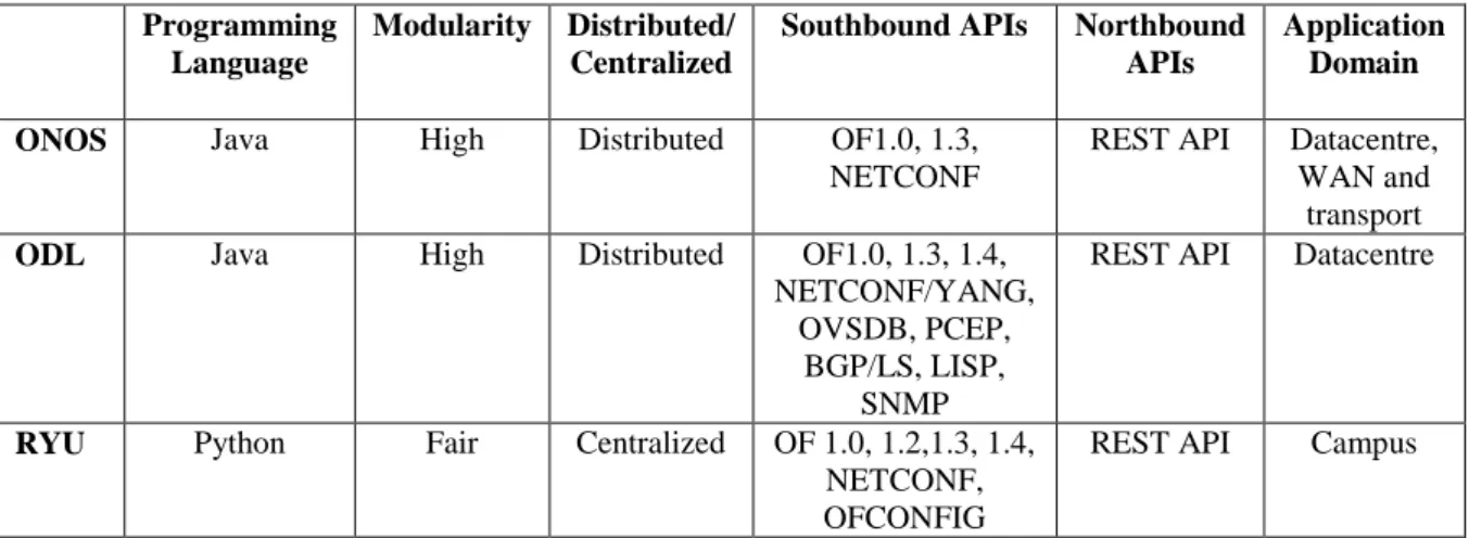
While many different NOSes exist, OpenDaylight and ONOS are notable as they are arguably the best candidates for production networks. The main differentiator between these two is that ONOS is primarily focused on carrier networks, while OpenDaylight originally focused on the data-centre [20]. These different focuses influence the architecture to some extent, as well as the available network applications.
14
A third controller, RYU, is relevant for this work as it is one of the most commonly used for research and development purposes. However, given that it has a centralized architecture, and therefore no resilience in the control plane, it is not suitable for a production carrier-grade network [20].
Table 1 presents a comparison of some of the features of these three controllers. A more exhaustive survey and comparison of most of the available controllers can be found in [20] and [2].
Table 1 - Feature based comparison of three popular SDN controllers
Programming Language
Modularity Distributed/ Centralized
Southbound APIs Northbound APIs
Application Domain
ONOS Java High Distributed OF1.0, 1.3, NETCONF
REST API Datacentre, WAN and
transport ODL Java High Distributed OF1.0, 1.3, 1.4,
NETCONF/YANG, OVSDB, PCEP,
BGP/LS, LISP, SNMP
REST API Datacentre
RYU Python Fair Centralized OF 1.0, 1.2,1.3, 1.4, NETCONF, OFCONFIG
REST API Campus
2.1.4.
Northbound API
The northbound API is the interface between the NOS and the network applications which calculate the forwarding state of the switches, based on high level network strategies and goals. The abstractions and functionalities provided by the NOS must be made available to the applications through the northbound interface.
Unlike the southbound, where OpenFlow is widely-adopted, the northbound interface does not yet have a widely-adopted, standardized protocol. Although some standardization organizations are working on a northbound API [23], the common trend in software is likely to occur, where standards typically follow implementation [2].
Currently, most controllers have at least two northbound APIs. The first is a programmatic interface, specific to the controller. This requires the application to be written in the same language as the controller, and allows the application to read network state, be updated with new topology information, and program the switches. This approach is useful as it allows the NOS to notify the application when new information is available, and the interaction between
15
the application and the NOS can make use of all the features of the programming language. The second API generally provided is a representational state transfer (REST) API. REST is a common architectural style used in web development, and allows a client to communicate with a server using a simple set of Hypertext Transfer Protocol (HTTP) methods. Since most controllers provide similar REST interfaces, network applications could be adapted to work with another controller with less work than the programmatic interface would require. However, REST APIs have a number of architectural constraints. A significant constraint of the REST interface is that the application cannot subscribe to notifications about new information, but must continuously poll the NOS. This can result in a significant processing overhead, or a significant delay in receiving new information.
2.1.5.
Network applications
Network applications contain network goals and business policy, and calculate the forwarding state of the switches accordingly. Common goals are routing, isolation, security, traffic engineering, and load balancing [2]. Many NOS vendors provide a number of network applications to cover common functionalities. The preferred approach is a modular or micro-service approach [20], where each application is responsible for one specific function. This allows for these applications to be easily reused in different combinations, depending on the particular use case.
The majority of popular NOSes are open-source, allowing users to modify the internals of the controller, as well as develop new applications to meet their own requirements. This allows for a faster pace of innovation than the traditional model of relying on vendors to introduce new features.
2.2.
Carrier Network Routing Protocols
To properly discuss FRR strategies in carrier networks, it is necessary to first understand the routing protocols used in these networks. Operators often make use of MPLS in the core of their network. The original benefit of MPLS was that MPLS switches could operate faster than IP switches, but as switching hardware has improved, this benefit has largely fallen away. MPLS has other benefits that are still relevant, such as traffic engineering and quality of service (QoS) capabilities [10], as well as the ability to transport a variety of traffic protocols. However, some scalability issues have been identified with the traffic engineering solutions in MPLS, and a new routing protocol, segment routing (SR), has recently been proposed. Segment routing
16
has a number of benefits, and can utilize the MPLS data plane without modification, possibly allowing for a phased introduction.
2.2.1.
Multiprotocol Label Switching
In IP networks, each switch runs a routing algorithm to determine the next-hop for a particular traffic flow, based on the IP packet header [24]. In an MPLS network (Figure 7), however, routing algorithms are only run at the edge of the network, in the provider edge (PE) routers [25]. The PE router determines the path that the traffic should take through the network, and assigns a short, fixed-length MPLS label accordingly. Paths corresponding to the different labels are installed in the interior provider (P) routers, using a forwarding table [24]. These paths are called label-switched paths (LSPs), since the P routers switch traffic based only on the MPLS label.
MPLS enables QoS in the network by creating different LSPs for the same path, that have different priorities. Traffic engineering is enabled with the Resource Reservation Protocol – Traffic Engineering (RSVP-TE), which allows LSPs to be created that take into account network constraints and traffic requirements.
Although the interior P routers are simplified by MPLS, as they do not have to run a routing algorithm to make forwarding decisions, a large amount of network state is still required to be stored in these routers. Each LSP requires an entry in the P router, and it has proven difficult for providers to cope with the thousands of paths often needed in the network [15].
2.2.2.
Segment Routing
Segment routing is similar in concept to MPLS in that it uses labels for routing, but unique labels are assigned to nodes (and links, if required), instead of being assigned to paths. At the
Figure 7 – An MPLS network topology showing P and PE routers [25] PE
PE
P P
P P
17
edge of the network, PE routers attach a stack of labels to the traffic that defines its path through the network [15]. The forwarding table of each P router therefore only contains entries for each node in the network, and not for each LSP. In this way, the network state is removed from the core of the network, and is only held in the edge routers.
This approach is very flexible, as PE routers can specify the traffic’s path with various levels of granularity by either attaching a single label, specifying the final PE, or it can specify intermediate nodes as well. If too many labels are attached, issues may arise with MPLS switches that only support attaching a limited number of MPLS labels to a particular packet. However, various techniques can be used to minimize the stack depth while ensuring the optimal path is used [26]. A number of prototype SDN controllers have been developed showing that SR is a viable SDN forwarding protocol [27] [28].
To illustrate the operation of segment routing, a SR network is shown in Figure 8, where each node has a unique SR label between 9000 and 9007. Links can be labelled with an adjacency label, as shown for the two links between node 9002 and 9005. Adjacency labels are only significant to a specific node. Incoming traffic at PE1 that is destined for PE2 can be labelled with a single label, 9002. The traffic would then take the shortest path through the network, which would be determined by the routing protocol used and the link weights. With equal link weights, the traffic would be load-balanced over multiple paths if the routing protocol supports equal-cost multipath (ECMP) routing.
However, a specific path can also be enforced by attaching additional labels for intermediate nodes. For example, to force the traffic through node 9002, the edge router would simply push the label stack 9002, 9007. Traffic would still be load balanced over ECMP paths, if available. To explicitly specify the entire route, including a specific link, the edge router can push the label stack 9001, 9002, 2023, 9006, 9007.
Figure 8 – A SR network showing node and adjacency labels [15]
PE1 PE2 as 9000 as 9001 as 9002 as 9003 as 9004 as 9005 as 9006 as 9007 as 2023 as 2032
18
2.3.
Data Plane Failure Recovery
As discussed in Chapter 1, there are two basic approaches to responding to data plane failures. A reactive recovery approach will only recalculate the forwarding rules once a failure has occurred, and there may be traffic loss for several seconds. A proactive approach pre-emptively installs back-up forwarding rules in case of a failure, which can reduce traffic loss to below 50 ms. This section provides more detail on each of these approaches, focusing on implementations in SDN.
2.3.1.
Reactive Approaches
In traditional networks with distributed control planes, data plane failures are communicated to other nodes by broadcasting the information as a topology change. Nodes then re-compute the forwarding tables accordingly. The time involved in distribution of the information and re-computation defines the minimum time for responding to the network failure [4]. This can be a lengthy process in some networks, as the information must travel through multiple hops, and the processing time of the routing algorithm is constrained by the computing power of the switches.
In a software-defined network, there are five basic steps that occur in order to recover from a failure, as shown in Figure 9 [16]. In order, they are:
1. A switch detects the failure
2. The switch notifies the controller of the failure 3. The controller computes the required updates 4. The updates are pushed to the switches 5. The switches update their forwarding table
19
Figure 9 - The five steps that must occur when a failure occurs [16]
This process could be faster than in a traditional network, and at least will not be worse. This is because the switches communicate the change directly to controller, rather than flooding the network, and the controller can run on more powerful server hardware than the weak management CPUs in switches [16].
Therefore, the restoration time (𝑇𝑟) can be broken down into four main components, as shown
in Equation (1) below. These are the failure detection time (𝑇𝑑), the switch-controller communication latency (𝑇𝑐𝑠), the computation time (𝑇𝑐), and the flow installation time (𝑇𝑖).
𝑇𝑟 = 𝑇𝑑 + 2𝑇𝑐𝑠+ 𝑇𝑐+ 𝑇𝑖 (1)
The restoration requirement specifies that traffic must be redirected within 50 ms of the failure being detected [29], and therefore the 50 ms requirement does not include 𝑇𝑑. However, the failure detection time 𝑇𝑑 is still important, as it is critical to minimizing traffic loss. A commonly used network protocol to detect link or node failures is Bidirectional Forwarding Detection (BFD) [11]. Two nodes establish a session over a particular path, and exchange frequent control messages to confirm that the path has not failed [17]. Alternatively, a simple loss-of-signal (LOS) approach can be used [11].
20
Sharma et al. used BFD sessions established between the path end-points to detect failures within 40 to 44 ms [11]. By using per-link BFD sessions instead, and increasing the frequency of the control messages, van Adrichem et al. were able to reduce the detection time to approximately 3 ms [17].
The switch-controller latency 𝑇𝑐𝑠 is largely a function of the network between the switch and controller, and will depend on the network. This factor can be reduced by geographically distributing the controller instances, so that each switch has a nearby controller. The network between the switch and controller could also possibly be improved. Both of these steps would increase the cost of the network, and the physical properties of the transmission link would still pose a restriction, since the latency of an optical fibre link is approximately 1 ms per 200 km [30]. A possible solution would be to first determine the maximum allowable value for 𝑇𝑐𝑠 by measuring the other variables in Equation (1), and then designing the network to achieve this value.
The computation time 𝑇𝑐 is dependent on a number of factors, such as the routing application, the controller performance, and the hardware the controller is running on. The performance of the controller in terms of responses per second and response time appears to be high enough to meet carrier-grade requirements. A comparison of the most popular controllers found most of the controllers tested had a response time of less than 10 µs, and many can process upwards of a million responses per second [20]. This does not include the recalculation time, which depends on the number of flow rules that must be recalculated, and has been found to exceed 100 ms in several implementations [11] [31].
Finally, the flow installation time 𝑇𝑖 is determined by the switch implementation. Flow installation times for a popular software switch, Open vSwitch, were found to be around 1 ms per flow installation [32]. These results are several years old, but show that flow installation could become a significant bottleneck in large-scale networks using software switches, if performance has not improved in recent years. Hardware switches are more likely to be used in a carrier network, however, and these should have a lower installation time.
Given that the four variables that contribute to the total restoration time in Equation (1) are all in the millisecond timescale, it appears unlikely that a restoration approach will be viable to meet the carrier-grade requirement of 50 ms. Furthermore, given that two of these variables,
𝑇𝑐 and 𝑇𝑖, are dependent on the number of flows affected, a restoration approach will have scaling limitations.
21
2.3.2.
Proactive Approaches
Traditional approaches to fast reroute (FRR) were described in Chapter 1.1. Similar concepts can be applied in SDN, where the global network view of the network simplifies the task of calculating the optimum back-up paths. In addition, the programmability of the network could alleviate some of the network management complexity of current FRR solutions, which has limited its deployment in production networks. In an SDN FRR solution, there are two main tasks: calculating the optimum back-up paths before a failure occurs, and configuring the data plane to use the back-up paths as soon as a failure occurs. This section will first discuss the process of configuring the data plane, and then discuss approaches to calculating the back-up paths.
Data plane configuration
In contrast to reactive approaches, proactive approaches to SDN data plane resilience preconfigure the switches to allow them to reroute traffic onto a back-up path without involving the controller. In a proactive strategy, there are two steps that the data plane must take in order to restore traffic:
1. A switch detects the failure
2. The switch selects the back-up rules
The restoration time calculation is modified from Equation (1) to reflect these two steps, and presented in Equation (2) below, where 𝑇𝑠 represents the time taken to select the back-up flow rules.
𝑇𝑟 = 𝑇𝑑 + 𝑇𝑠 (2)
The failure detection method is just as critical as in a reactive approach, and the same methods can be used. It is typically the most significant factor in the traffic restoration time, as the selection of back-up actions is very fast [17] [33]. Since the 50 ms requirement does not include the failure detection time, it is based only on 𝑇𝑠 for a proactive approach.
Two different methods of selecting the backup rules were proposed prior to the introduction of OpenFlow fast failover groups in OpenFlow 1.1. The first project, OpenState, extends the OpenFlow traffic processing pipeline by introducing a finite state machine, allowing different sets of flow rules to be used depending on the state held in the switch [34]. When a failure is detected, the state of the switch changes, and a different set of rules are selected. This approach introduces additional complexity in the switch, which goes against some of the principles of
22
SDN. This, combined with the fact that it requires use of non-standard protocol, means that is unlikely to see much real-world adoption.
The second proposal was to install back-up rules into the same flow table as the primary rules, but with a lower priority. An auto-reject mechanism was implemented, which automatically deleted the primary rules when a failure occurred, causing the back-up rules to be selected [33]. Back-up actions are installed per-path, as requested, and require additional flow rules for each possible link and node failure on the protected path. This leads to a high number of flow rules needed, even in small to medium size networks. This approach also requires an extension of the OpenFlow protocol, and fast failover groups in later OpenFlow standards perform the same function, so it is also unlikely to see real world adoption.
OpenFlow fast failover groups allow the status of a port to influence the forwarding actions that are applied to a traffic flow, as explained in section 2.1.1 of this chapter. This implementation has the advantage that it does not require additional matching rules in the flow table, and it is a standard OpenFlow protocol which is already widely adopted.
Several works have implemented a protection scheme using the OpenFlow fast failover groups, and have shown that the recovery time is independent of path length and network size, since it is a local action [17].
Using per-path BFD to detect failures, Sharma et al. achieved a recovery time of 42 – 48 ms [11]. By using a per-link BFD configuration with more frequent control methods, van Adrichem et al. achieved a recovery time of 3.3 ms [17], which is substantially faster than the 50 ms requirement for carrier grade networks. This recovery time also includes the failure detection time.
However, implementing a fast reroute scheme that provides protection against all or most failures is not as simple as configuring a fast failover group to output traffic to a different port. The existence of an adjacent LFA is topology dependent, and often traffic must be forwarded to a remote LFA.
A common SDN approach to ensure that the traffic is forwarded to the RLFA is to install back-up flow rules in each switch along the back-up path. Packets are tagged at the point of local repair to notify other switches that they should be forwarded according to the back-up rules [18] [34] [35]. Once the traffic reaches the RLFA, the tag can be removed, and the primary forwarding rules used to reach the destination [35].
23
Back-up rule calculation
An early approach to calculate back-up rules took an end-to-end path protection approach, using disjoint paths [36]. Disjoint paths are paths that do not share any link or node, besides the end points. MPLS was used in the data plane, with a primary label switched path (LSP), as well as a disjoint back-up LSP. The end point switches monitored the connectivity of the primary path and switched over to the back-up path when the primary path failed. However, using disjoint paths is inefficient as the resulting primary path can be substantially longer than the shortest path possible [35]. Additionally, a single failure on a multi-hop path would cause the capacity of all the links to be wasted.
A later attempt, implemented on top of OpenState, used an approach where the traffic is tagged and sent back along the primary path after a failure, until a node is reached that can calculate a suitable alternate path to the destination. The tagged packets signal the failure to this repair node, and all subsequent packets are redirected down this alternate path [34]. This approach essentially selects a remote LFA on the primary path, at a point before the failure. However, a more optimal RLFA could easily exist that is not on the primary path. This approach will result in packets arriving out of order, which may be a problem for certain protocols. The initial paths for the repair traffic are relatively long, and could possibly be shortened by using the optimum RLFA. A further drawback of this approach is that it uses a custom OpenFlow extension, and adds extra state into the nodes.
Finally, a solution for IP networks was proposed by van Adrichem et al. [35]. This approach recognises that traffic can be re-routed along the primary path, to only avoid the failure, and still use the other available links. This is more efficient than a disjoint path method, which avoids all resources along the primary path. To calculate the back-up route in case of a specific failure, the element (link or node) is removed from the network graph, and the new shortest path found. This shortest-path is installed in the nodes along the path as additional forwarding rules, that match on the tag added by the node that detected the failure. The back-up action tags the traffic with information of the failure so that the correct forwarding rules are selected in following switches. This essentially creates a tunnel to the RLFA, where the tag is removed and the traffic uses normal primary forwarding rules to reach the destination. Traffic engineering was not considered in this approach, and the presence of multiple equal cost paths required significantly more rules to be installed. In addition, the solution does not support multiple parallel links, called link aggregates, between two nodes. Carriers often use traffic
24
engineering, link aggregates, and equal cost multipath routing (ECMP) for load balancing, so a carrier solution would require these issues to be addressed.
2.4.
Chapter Discussions
This chapter first presented an overview of the SDN architecture, with a focus on fast failover groups, which are useful for a fast reroute strategy. Secondly, some background on carrier routing protocols was presented. Some of the challenges of reactive approaches to data plane failures were highlighted, as well as current efforts in this area. These challenges will make it difficult to achieve scalable carrier grade resilience with a reactive approach. Finally, the data plane support for proactive strategies was discussed, and the challenges in the control plane calculation of the back-up rules highlighted. Many current solutions have inefficient back-up paths, with the most suitable solution for IP networks being proposed by van Adrichem et al. However, a carrier solution would require some additional features, such as support for link aggregates, ECMP routing, and traffic engineering.
The following chapter will introduce the requirements of a FRR approach for carrier networks in more detail, as well as the design of the proposed solution. The requirements and design of a suitable network testbed for evaluation is also presented.
25
Chapter 3
Requirements and Design of a Carrier Grade SDN FRR Solution
Chapter 2 presented the current work on fast reroute solutions for SDN. The main aim of this dissertation is to develop a solution for the core of carrier grade networks, and therefore it is important to consider the requirements of these networks. This section will first look at carrier networks, specifically focusing on the core of the network. From this, the requirements of the proposed solutions will be formulated. The algorithm of the proposed solution will then be presented.
3.1.
Carrier Core Network
This section details the architecture of a typical carrier network, and then considers the topology and functions of the core network. The requirements of the core network are then discussed, and used in section 3.2 to determine the requirements of the FRR solution.
3.1.1.
Carrier Network Architecture
Due to the scale of national carrier networks, operators of these networks typically use a three-tier hierarchical network model to design a reliable, scalable and cost-efficient network [37] [38]. The three layers are: the access layer, the distribution layer, and the core layer.
26
Figure 10 shows an example network topology using these three layers. The access layer is referred to as the ‘last-mile’ part of the network, and provides connectivity and access to the customers by connecting to customer premises equipment (CPE). The distribution layer aggregates traffic from the access layer for transport on the core layer, provides policy-based connectivity, and is the boundary between the core and access layers. As it connects resources in the city or town it is located in, the distribution layer is also referred to as the metropolitan area network. Finally, the core layer connects the distribution network layers from different geographical areas, typically over long distances [38].
3.1.2.
Core Network Topology
An example of a typical carrier core network topology in the United States is presented below in Figure 11. An interesting characteristic to note is the low number of links per node. A survey of 11 service provider core networks found the number of nodes ranged from 16 to 600, and the average node-to-link ratio was 1:2.3 [39].
Figure 11 - Example core network for a US carrier [38]
A second important characteristic is the use of multiple links between two nodes, forming an aggregate link. In addition to single link and node failures, the fast reroute solution must take into account the various failure scenarios for these aggregate links. If a single link in the aggregate should fail, the optimum back-up path will likely use another link in the aggregate.
27
However, it is likely that the entire aggregate could fail at once (which is still classified as a single failure) due to a line cut or node failure. The FRR solution must take different actions for these different scenarios, and not simply avoid the entire aggregate if one link in the aggregate fails, as this would be inefficient.
3.1.3.
Core Network Requirements
The function of the core network influences its design and requirements. The main requirements of the core layer are as follows:
Provide high-speed switching [37]
Provide reliability and fault tolerance [37]
Provide traffic engineering functions [38]
Support multiple types of traffic [40]
High-speed switching is required to switch large amounts of traffic quickly, while minimising the cost of the networking hardware. While modern routers can implement fast IP header lookups and path calculations in hardware, these devices are expensive. A label switching protocol like MPLS provides a more efficient solution by performing the path calculation once, at the edge of the network, and assigning a short label accordingly. Cheaper switches, as opposed to routers, then switch the traffic in the core of the network based on this label.
As mentioned previously, for the core network to be considered carrier-grade, the fault tolerance requirement is that traffic must be redirected away from a failure within 50 ms of the failure being detected [11]. A specific example of this specification can be found in the standard for MPLS Tranport Profile [29].
Carrier networks require traffic engineering functions in order to utilise the network resources efficiently and cost-effectively. For complex networks, this requires the use of a routing protocol that can allocate resources to specific traffic flows, as well as define explicit routes for traffic flows [38].
Finally, the network should support multiple types of traffic, such as voice, data, and multimedia. This allows consolidation of different networks, like the public switched telephone network (PSTN) and the IP network, into one network, reducing costs [40].
![Figure 1 – Traditional operational planes of a router [6]](https://thumb-us.123doks.com/thumbv2/123dok_us/10174883.2919794/16.892.272.607.527.703/figure-traditional-operational-planes-router.webp)
![Figure 2 - High-level SDN architecture [7]](https://thumb-us.123doks.com/thumbv2/123dok_us/10174883.2919794/17.892.152.573.359.754/figure-high-level-sdn-architecture.webp)
![Figure 4 - A simplified view of the SDN architecture [2]](https://thumb-us.123doks.com/thumbv2/123dok_us/10174883.2919794/24.892.226.661.742.1080/figure-simplified-view-sdn-architecture.webp)
![Figure 5 - Breakdown of an OpenFlow rule [2] [52]](https://thumb-us.123doks.com/thumbv2/123dok_us/10174883.2919794/25.892.136.772.553.816/figure-breakdown-openflow-rule.webp)
![Figure 6 - The OpenFlow fast-failover group [19]](https://thumb-us.123doks.com/thumbv2/123dok_us/10174883.2919794/26.892.291.621.110.413/figure-openflow-fast-failover-group.webp)
![Figure 8 – A SR network showing node and adjacency labels [15]](https://thumb-us.123doks.com/thumbv2/123dok_us/10174883.2919794/31.892.251.680.901.1090/figure-sr-network-showing-node-adjacency-labels.webp)
![Figure 9 - The five steps that must occur when a failure occurs [16]](https://thumb-us.123doks.com/thumbv2/123dok_us/10174883.2919794/33.892.240.695.102.586/figure-steps-occur-failure-occurs.webp)
![Figure 10 - Three tier hierarchical network [37]](https://thumb-us.123doks.com/thumbv2/123dok_us/10174883.2919794/39.892.162.750.709.1093/figure-tier-hierarchical-network.webp)

