Quartzglass-Micropipettes
Product Specifications
•
Outer diameter of pipette fiber is 100-120µm
•
Very flexible quartz-glass fiber can be strengthened with metal tube
or glass pipette to be mounted to a manual microdrive system
•
Available for use with any standard manual manipulator system or
with Thomas RECORDING multielectrode microdrives (“System
Eckhorn” or “Mini Matrix”)
•
Software controlled microinjection pump system available
Fell free to ask for your custom made microinjection solution!
PRODUCT DESCRIPTION
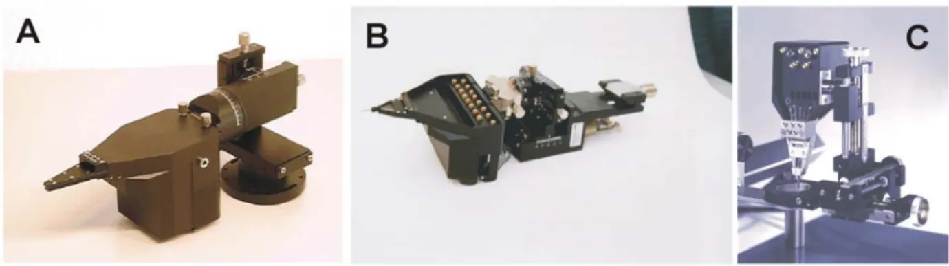
The micropipette fiber has an outer diameter of 100-120µm and is made of quartz-glass. Beside microelectrodes the micropipettes can be used in our multielectrode manipulator systems (“System Eckhorn” or “Mini Matrix”, see figure 1) for drug injection through the pipette and simultaneous recording of the neural drug response with the microelectrodes.
Furthermore the micropipettes are available for use with any standard manual micromanipulator system (see figure 2).
Figure 1: TREC Microdrive systems. The micropipettes are available ready for use with our microdrive systems “System Eckhorn “ (A and B) and “Mini Matrix” (C”)
Figure 2: Micropipette strengthened with a glass pipette or a metal tube to be used in a standard manual microdrive.
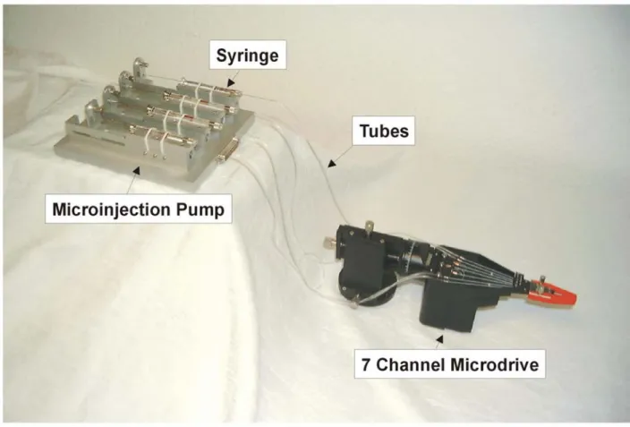
For drug injection we offer a software controlled microinjection pump system which is shown in figure 3. This system is available in a one and four channel version.
The use of quartz-glass microinjection pipettes in our 7 channel microelectrode manipulator “System Eckhorn” is described below.
Figure 3: 4 channel microinjection pump system connected to a 7 channel microelectrode manipulator „System Eckhorn” via tubes. The microinjection pump is equipped with 4 syringes. Drug injection with this pump is controlled by software.
The use of Micropipettes
in the Multiple-Electrode Manipulator
„
System ECKHORN
“
for neurophysiological tasks
Author: Materials and Tools are delivered exclusively by:
Wolfgang Kruse Fachbereich Physik, Arbeitsgruppe Biophysik, Philipps-Universitaet Marburg Renthof 7, D-3550 Marburg Internal Report 12/1990 Thomas RECORDING GmbH Winchester Strasse 8 Europaviertel D-35394 Giessen Email: [email protected] Web: www.ThomasRecording.com
Contents:(extended version for UWE THOMAS RECORDING, 04/92) 1. General considerations on the use of micro-pipettes
2 Handling of pipettes 2.1 Tip-pulling
2.2 Tip-grinding 2.3 Tip coating
2.4 Connection to a pressure-micropump 2.5 Filling with fluids
2.6 Loading in Multiple-Electrode-Manipulator 3 Lessons learned using micro-pipettes 3.1 Pressure-injection of HRP
3.2 Pressure-injection of Lidocaine
1. General considerations on the use of micro-pipettes
The Multiple-Electrode Manipulator “System ECKHORN” is a powerful device for positioning an array of fiber-electrodes in neuronal tissue. According to the small shaft-diameter of the single electrodes it allows the parallel placement of multiple electrodes with a inter-electrode-spacing down to 250 µm.
Micro-pipettes can provide equivalent capabilities, assuming that the outer diameter of the pipette is comparable to the diameter of the fiber-electrode. To achieve this, we used the same quartzglass tubes as for the tungsten-quartzglass electrodes. The tube was high-temperature-pulled to an outer diameter of 100..120 microns (Uwe Thomas). With regard to the mechanical stability and the inner volume of the pipette, a ratio of 2 between outer diameter and the inner diameter has been found most advantageous for our purposes. This ratio can be varied over a wide range by selecting appropriate quartz-tubes as base-material. The ratio between inner and outer diameter remains constant during the pulling procedure. (Fig.1 a)
2. Handling of pipettes
The handling of fiber-electrodes requires extreme caution. Very small forces perpendicular to the axis of the electrode can cause damage to the quartz shield. A crack in the lower part of the electrode (towards the tip) causes mechanical and/or electrical problems.
In the upper part of the electrode (above the translation-sled), the damage to the quartz shield must be accepted as a consequence of contacting the electrode electrically. Of course, any damage to the quartztube of the pipette destroys the whole pipette (and in most cases a lot of work, which has been spent on the pipette up to this point).
Pipettes are even more sensitive to unbalanced forces than fiber-electrodes.
ln addition to the danger of breaking the pipette as an effect of bending, the pipettes can be broken by tangential pressure as well. This has to be taken into consideration for the pressure caused by the mechanical coupling in the translation-sled.
2.1 Tip-pulling
The tips of the pipettes can be pulled with the same high-temperature tip-puller which is also be used for the fiber-electrodes. This tip-puller as well as the pipette raw material is available from Thomas RECORDING. In our experiments we usually applied pipettes (total length of 45 cm) with a tip-length of 900 to 1100 µm (see Fig. 1b).
Long tips are appropriate for pipettes with larger diameter (~ 110 µm), because the tip-angle A decreases and the friction during the progressive movement through the tissue is reduced. The end of the pulled tip is cut with a razor blade to allow a proper grinding of the tip.
2.2 Tip-grinding
The tip is grinded on a diamond grinding-disk. Deviating from grinding of electrodes the pipettes are not spinned during the grinding procedure.
The grinding-disk does not rotate in the direction against the tip (as it does during the grinding of electrodes) instead it rotates in the same direction as the tip looks. This kind of grinding avoids the self-filling of the pipette with the grinding-fluid. The grinding of the tip from one side yields to an oval opening at the end of the tip. The outer tip-diameter was estimated with a microscope to about 30 µm (Fig. 1 c).
2.3 Tip coating
To avoid problems resulting from the contact between the pipette and physiological fluids (eg. liquor, blood), the tip of the pipette was treated with an anti-adhesive fluid (U. Thomas). This fluid was successfully applied as a protective coating on electrode tips already. In several cases pipettes could be used a second time, provided that no damage to the tip geometry had occurred.
2.4 Connection to a pressure-micropump
Up to now micro-pipettes are used for pressure-injections in cortical tissue only at our laboratory. For this application the not-pulled, open end of the pipette must be connected to a pumping device.
A simple connection is made by using a polyethylen hose, which is fixed to the pipette by a short stainless-steel tube (Fig.2).
The tube (ab. 20 mm length) is pushed on the end of the pipette and fixed to it by shellac. The stainless-steel tube should be light enough to be held by the pipette without breaking it. Further on it must be long enough to allow a proper fixation of the polyethylen hose without touching the pipette itself with the fingertips.
2.5 Filling with fluids
Before the filling-procedure takes place, the upper end of the pipette was connected to a simple pumping device (for example a 1-ml-medical syringe).
The connection can be made with a piece of polyethylene-hose (several cm), following the procedure specified above.
For fluids with low viscosity (Ringer´s solution etc.), the filling is performed through the tip of the pipette. When the tip of the pipette is placed into a drop of the fluid, the pipette may fill itself by the capillary forces of the fluid.
Often this self-filling appears to be very slow or stops after some centimeters, when the capillary force is in equilibrium to the friction between fluid and glass tube. By applying a soft suction with the manually driven “pressure device”, a direct control of fluid-movement is possible.
Additionally, the filling through the tip allows a mixture of different fluids in one pipette, provided that the single fluids are separated by small bubbles of air.
The filling with fluids of higher viscosity than water may require another filling-procedure, which fills the pipette through the back. This also might be the appropriate procedure for pipettes which are to be filled with a high-molar solution. The backward filling doesn1t allow the use of different fluids in one pipette.
In our experimental applications using micro-pipettes, the exact measurement of the injected amount was of high interest. A direct method was applied by placing some markers behind the fluid which should be injected. The markers usually consisted of little amounts of intensive stains (e.g. Thionine), which are visible in the inner of the micro-pipette. Each injection causes a movement of those markers and the injected amount can be computed by the movement of the marker and the known inner diameter of the pipette.
A filled pipette can be stored several days without damage, as long as the fluid doesn't reach into the tip of the pipette. Pay attention to this, otherwise the fast drying of the fluid in the opening of the tip may cause a crystalline barrier in the pipette-tip within several minutes. Because of this, a filled pipette should be stored (and transported) preferably in a horizontal position.
2.6 Loading in Multiple-Electrode-Maninulator
The installation of micro-pipettes in the Multi -Electrode-Manipulator requires an additional mounting-device, on which the pipettes can be fixed at their upper end (using the stainless-steel tubes). This panel has to be attached to one side of the manipulator. As mentioned above the installation of the pipettes in the Multi-Electrode-Manipulator requires a special adjustment of the forces which are applied by the brakes of the translation-sled. Because these brakes exert a perpendicular pressure to the pipettes, they constitute an additional source of damage to the pipettes.
The procedure of loading the pipettes in the manipulator is the same as for the electrodes. To prevent breaking of the pipettes, one has to avoid any sharp bends of the pipette during the loading. The fixation on the mounting-device has to provide the necessary length of the pipette, which is needed for the progressive movement into the tissue.
3. Lessons learned using micro-pipettes
Micro-pipettes have been used at our laboratory for pressure injections into area 17 and 18 of cat visual cortex. As the most experiments were performed under semi-chronic conditions we penetrated in several cases the intact dura of cat cortex.
It appeared, that the frontmost edge of the grinded pipette was in general as sharp as the conically formed tip of an electrode.
In some cases there occured problems after positioning the pipettes in cortical tissue. Even if the tip of the pipette was free directly before penetrating the dura, the pipette was blocked after the movement through the tissue. Presumably these problems are caused by tissue, which is pressed into the tip.
During the following experiments this problem was avoided by applying a smooth pressure to the fluid in the pipette during the movement through the tissue.
3.1 Pressure-injection of HRP
First successful applications of pressure-injections of HRP with this type of micro-pipettes had been performed by J. Leferink. The procedures used are documented in his medical doctor thesis (Leferink, 1989; Funktionelle Anatomie der Verbindungen zwischen primaeren Arealen der Sehrinde). The results are partially published as an abstract (Leferink, J., Eckhorn, R., Nelson, J.J., and Wagner, H.-J. (1987); Characterization of patchy projection systems between cortical areas: A combined multi-electrode and HRP study in cat's visual cortex. Neuroscience 22, Suppl., 1305P).
In these applications the pipettes had been used together with a separate manipulator for every single pipette. Deviating from the technique described above, the pipette was connected to the pumping-device with a flexible steel tube instead of using a polyethylene hose. The pumping-device consisted of a Hammilton-syringe with an absolute volume between 10 µl and 25 µl.
3.2 Pressure-injection of lidocaine
A further application using multiple micro-pipettes for pressure injections has been performed to achieve a local and reversible blockade of neuronal activities in area 17 and 18 of cat visual cortex.
Because of the problems caused by the glued connection between steel tube and the pipette I preferred the more flexible technique using the polyethylene hose for the Lidocaine-injections.
During the injections changes in the local activity have been recorded from the neighboring electrodes. Amounts down to 30 nl were successfully injected.
There was only little line-interference detected when pipettes were placed in cortical tissue. Preliminary results have been published as an abstract (Kruse, R. Eckhorn and R. Bauer (1990): Stimulus-induced Synchronization among three visual cortical areas of the cat, Perception 19, A55c).
3.4 Possible use of micro-pipettes for iontophoretic injections
There may be the possibility to use this type of micro-pipettes for iontophoretic injections as well. Several alterations of the pipettes and the manipulator are under discussion. The required technique wasn't developed any further at our lab so far.
D:\Paper\Microinjection.pdf