Document type: Error! Reference source not found. Document subtype: Error! Reference source not found. Document stage: Error! Reference source not found.
ISO/IEC JTC 1/SC 29
Date: 2003-12-12ISO/IEC FCD 2.0 15444-9 Study Text
ISO/IEC JTC 1/SC 29/WG 1 Secretariat: JISC
Information technology — JPEG 2000 image coding system — Part 9:
Interactivity tools, APIs and protocols
Technologie de l'information — JPEG 2000 système de codage d'image — Partie 9: Outils d'interactivité, APIs et protocoles
Copyright notice
This ISO document is a Draft International Standard and is copyright-protected by ISO. Except as permitted under the applicable laws of the user's country, neither this ISO draft nor any extract from it may be reproduced, stored in a retrieval system or transmitted in any form or by any means, electronic, photocopying, recording or otherwise, without prior written permission being secured.
Requests for permission to reproduce should be addressed to either ISO at the address below or ISO's member body in the country of the requester.
ISO copyright office
Case postale 56 • CH-1211 Geneva 20 Tel. + 41 22 749 01 11
Fax + 41 22 749 09 47 E-mail [email protected] Web www.iso.org
Reproduction may be subject to royalty payments or a licensing agreement. Violators may be prosecuted.
Contents
Page Foreword...viii Introduction ...ix 1 Scope ...1 2 Conformance...2 3 Normative references ...24 Terms and definitions ...3
4.1 HTTP definitions ...3
4.2 JPIP definitions ...3
5 Symbols (and abbreviated terms) ...5
6 General description ...6
6.1 JPIP protocol...6
6.2 Purpose...7
7 Common BNF definitions...7
7.1 General...7
7.2 Integers and character sets ...7
7.3 File format elements ...9
Annex A (normative) The JPP-stream and JPT-stream media types... 10
A.1 Introduction ... 10
A.2 Message Header Structure ... 10
A.3 Data-bins... 14
A.4 Conventions for parsing and delivery of JPP- and JPT-Streams (informative) ... 22
Annex B (normative) Sessions, Channels, Cache Model and Model-sets ... 24
Requests Within a Sessions vs. Stateless Requests... 24
B.2 Channels and Sessions ... 24
Cache Model Management... 25
B.4 Interrogation and Manipulation of Model-Sets ... 25
Annex C (normative) Client request ... 27
C.1 Request syntax ... 27
C.2 Target identification fields ... 29
C.3 Fields for working with sessions and channels ... 30
C.4 View-window request fields... 32
C.5 Metadata request fields... 38
C.6 Data limiting request fields... 41
C.7 Server control request fields ... 42
C.8 XPath query request fields ... 44
C.9 Cache management request fields ... 45
C.10 Upload request parameters ... 51
C.11 Client capability and preference request fields... 51
Annex D (normative) Server response signalling... 58
D.1 Reply syntax... 58
D.2 JPIP Response headers ... 60
D.3 Response data ... 64
D.4 XPath query results ... 65
Annex E (normative) Uploading images to the server ... 68
E.1 Introduction ... 68
E.3 Server response ...69
E.4 Merging data on the server...70
Annex F (normative) Using JPIP over HTTP ...72
F.1 Introduction...72
F.2 Requests ...72
F.3 Session Establishment ...73
F.4 Responses ...74
F.5 Additional HTTP features...75
Annex G (normative) Using JPIP with HTTP requests and TCP returns...77
G.1 Introduction...77
G.2 Client Requests ...77
G.3 Session Establishment ...77
G.4 Server Responses ...78
G.5 TCP and length request field (Informative)...79
Annex H (normative) Using JPIP with alternate transports...80
H.1 Introduction (Informative)...80
H.2 Reliable Requests with Unreliable Data (Informative) ...81
H.3 Unreliable Requests with Unreliable Data (Informative) ...82
H.4 Request and Response Syntax (Informative) ...82
H.5 Session Establishment (Informative) ...82
Annex I (normative) Indexing JPEG 2000 files for JPIP...84
I.1 Introduction (informative)...84
I.2 Identifying the use of JPIP index boxes in the JPEG 2000 file format compatibility list ...85
I.3 Defined boxes ...85
I.4 Association of codestream indexes with codestreams ...94
I.5 Placement restrictions (informative) ...94
Annex J (normative) Registration of extensions to this standard...95
J.1 Introduction to registration ...95
J.2 Registration Elements...95
J.3 Items which can be extended by registration ...95
J.4 Registration Process...97
J.5 Timeframes for the registration process ...97
Annex K (informative) Application Examples ...98
K.1 Introduction...98
K.2 Searching embedded XML using XPath...98
K.3 Use of JPIP with codestreams in other file formats ...99
K.4 Tile-part Implementation Techniques...100
K.5 JPIP protocol transcripts...100
Using JPIP with HTML...103
K.7 Example box-path values ...105
Annex L (informative) APIs ...106
Foreword
ISO (the International Organization for Standardization) and IEC (the International Electrotechnical Commission) form the specialized system for worldwide standardization. National bodies that are members of ISO or IEC participate in the development of International Standards through technical committees established by the respective organization to deal with particular fields of technical activity. ISO and IEC technical committees collaborate in fields of mutual interest. Other international organizations, governmental and non-governmental, in liaison with ISO and IEC, also take part in the work. In the field of information technology, ISO and IEC have established a joint technical committee, ISO/IEC JTC 1.
International Standards are drafted in accordance with the rules given in the ISO/IEC Directives, Part 2. The main task of the joint technical committee is to prepare International Standards. Draft International Standards adopted by the joint technical committee are circulated to national bodies for voting. Publication as an International Standard requires approval by at least 75 % of the national bodies casting a vote.
Attention is drawn to the possibility that some of the elements of this document may be the subject of patent rights. ISO and IEC shall not be held responsible for identifying any or all such patent rights.
ISO/IEC 15444–9 was prepared by Joint Technical Committee ISO/IEC JTC 1, Information Technology, Subcommittee SC 29, Coding of Audio, Picture, Multimedia and Hypermedia Information.
ISO/IEC 15444 consists of the following parts, under the general title Information technology — JPEG 2000 image coding system:
⎯ Part 1: Core coding system
⎯ Part 2: Extensions
⎯ Part 3: Motion JPEG 2000
⎯ Part 4: Conformance testing
⎯ Part 5: Reference software
⎯ Part 6: Compound image file format
⎯ Part 8: Secure JPEG 2000
⎯ Part 9: Interactivity tools, APIs and protocols
⎯ Part 10: 3-D and floating point data
⎯ Part 11: Wireless
Introduction
ITU–T Rec. T.800 | ISO/IEC 15444–1 (JPEG 2000) is a specification that describes an image compression system that allows great flexibility, not only for the compression of images but also for access into the codestream. The codestream provides a number of mechanisms for locating and extracting portions of the compressed image data for the purpose of retransmission, storage, display, or editing. This access allows storage and retrieval of compressed image data appropriate for a given application without decoding.
The purpose of this International Standard is to provide a network protocol that allows for the interactive and progressive transmission of JPEG 2000 coded data and files from a server to a client. This protocol allows a client to request only the portions of an image (by region, quality or resolution level) that are applicable to the client’s needs. The protocol also allows the client to access metadata or other content from the file.
Any organization contemplating the use of this International Standard should carefully consider the constraints on their applicability.
Information technology — JPEG 2000 image coding system —
Part 9: Interactivity tools, APIs and protocols
1 Scope
This International Standard defines, in an extensible manner, syntaxes and methods for the remote interrogation and optional alteration of JPEG 2000 codestreams and files in accordance with their definition in the following parts of ISO/IEC 15444:
⎯ ITU–T Rec. T.800 | ISO/IEC 15444–1:2002 and its definition of a JPEG 2000 codestream and JP2 file format.
⎯ the JPEG 2000 family of file formats as defined in further parts of ISO/IEC 15444.
In this International Standard, the defined syntaxes and methods are referred to as the JPEG 2000 Interactive Protocol, “JPIP”, and interactive applications using JPIP are referred to as “JPIP systems.”
JPIP specifies a protocol consisting of a structured series of interactions between a client and a server by means of which image file metadata, structure and partial or whole image codestreams may be exchanged in a communications efficient manner. This International Standard includes definitions of the semantics and values to be exchanged, and suggests how these may be passed using a variety of existing network transports.
With JPIP, the following tasks may be accomplished in varying, compatible ways: ⎯ the exchange of capabilities
⎯ the negotiation of capabilities to use in a session
⎯ the request and transfer of the following elements from a variety of containers, such as JPEG 2000 family files, JPEG 2000 codestreams and other container files
⎯ selective data segments ⎯ selective and defined structures
⎯ parts of an image or its related metadata
Further, JPIP provides the capability for ‘fallback,’ such that the protocol can deliver similar results using differing levels of awareness of JPEG 2000 file and codestream structures at the client and the server. JPIP can be used over a variety of networks and communications media having different characteristics and quality of service characteristics. It can use a number of methods to communicate between client and server, based on existing protocols and network transports, which this International Standard extends to provide additional JPEG 2000 related functionality. Information that is user or session related can also be exchanged.
JPIP can be tailored via the various extensions to the JPEG 2000 file format, as defined in ITU–T Rec. T.801 | ISO/IEC 15444–2, ISO/IEC 15444–3 and ISO/IEC 15444–6. However, to achieve a simple level of interactivity that allows portions of a single JPEG 2000 file or codestream to be transferred, these other capabilities are not mandated.
Although the terms ‘client’ and ‘server’ are typically used in this International Standard to refer to the image receiving and delivering applications respectively, it is intended that JPIP can be used within both hierarchical and peer to peer networks, for data delivery in either direction, and for machine to machine as well as user to machine or user to user applications. It is also intended for use as an adjunct to an alternative, more comprehensive, protocol for image delivery, and for the delivery of non-JPEG 2000 coded information. While some features of JPIP may be applied to codestreams that are not JPEG 2000 compliant, such use is not mandated or required by JPIP systems conforming to this International Standard.
The use of JPIP in an Internet or intranet environment is addressed. Further facilities and features may be available when JPIP is used on top of a network transport protocol such as TCP/IP, UDP or HTTP.
In addition, this International Standard defines two media-types: JPP-stream and JPT-stream.
2 Conformance
[Editor’s note: Add paragraph.]3 Normative
references
The following referenced documents are indispensable for the application of this document. For dated references, only the edition cited applies. For undated references, the latest edition of the referenced document (including any amendments) applies.
ITU–T Rec. T.800 | ISO/IEC 15444–1:2002, JPEG 2000 Image Coding System 2nd edition ITU–T Rec. T.801 | ISO/IEC 15444–2:2001, JPEG 2000 Image Coding System: Extensions ISO/IEC 15444–3:2002, JPEG 2000 Image Coding System: Motion JPEG 2000
ISO/IEC 15444–6:2003, JPEG 2000 Image Coding System: Compound Image File Format IETF RFC 793, Transmission Control Protocol, September 1981
IETF RFC 2045, Multipurpose Internet Mail Extensions (MIME) Part One: Format of Internet Message Bodies, November 1996
IETF RFC 2046, Multipurpose Internet Mail Extensions (MIME) Part Two: Media Types, November 1996 IETF RFC 2616, Hypertext Transfer Protocol — HTTP/1.1, June 1997
4 Terms and definitions
For the purposes of this document, the following terms and definitions apply. The definitions defined in ITU–T Rec. T.800 | ISO/IEC 15444–1:2000 Clause 3 and ITU–T Rec. T.801 | ISO/IEC 15444–2 Clause 3 also apply to this International Standard.
4.1 HTTP definitions
The following definitions are intended to match HTTP/1.1. In the case of any difference, these definitions should be used.
4.1.1 connection
4.1.2 entity
The information transferred as the payload of a request or response. An entity consists of metainformation in the form of entity-header fields and content in the form of an entity-body.
4.1.3
origin server
The server on which a given resource resides or is to be created. 4.1.4
proxy
An intermediary program which acts as both a server and a client for the purpose of making requests on behalf of other clients. Requests are serviced internally or by passing them on, with possible translation, to other servers.
4.2 JPIP definitions
The following definitions are used within this standard. In some cases, these definitions differ from those used in other standards and/or recommendations.
4.2.1
cache (client-side)
The cache on the Client is the storage of the JPIP data-bins. The Client may have a limited cache and may have to purge cached JPIP data-bins from time to time.
4.2.2 cacheable
A response is cacheable if a cache is allowed to store a copy of the response message for use in answering subsequent requests. Even if a resource is cacheable, there may be additional constraints on whether a cache can use the cached copy for a particular request.
4.2.3
cache-model (server-side)
The server’s estimation of the portions of the data-bins available to client. The server may add items to its estimation of the clients cache because it assumes successfully delivery or because it has received acknowledgements of transmitted data, or because of cache-model update statements.
4.2.4 channel
A mechanism for grouping requests and responses such that only one request/response is active at a time within the group. Multiple simultaneous requests and responses require multiple channels.
4.2.5 client
A program that establishes connections for the purpose of sending requests. 4.2.6
data-bin
A set of bytes of the same type of data which may be partially delivered. 4.2.7
JPIP index table
A file format box which provides information about the location of portions of a file or codestream. 4.2.8
logical target
4.2.9 message
A set of bytes from a single data-bin and the header identifying those bytes and the data-bin. 4.2.10
request
A group of fields and values sent from the client to the server to obtain portions of an image or metadata. 4.2.11
response
The bytes sent from the server to the client after receiving a request. 4.2.12
resource
A network data object or service that can be identified by a URI. A HTTP target. 4.2.13
server
An application program that accepts connections in order to service requests by sending back responses. Any given program may be capable of being both a client and a server; use of these terms refers only to the role being performed by the program for a particular connection, rather than to the program’s capabilities in general.
4.2.14 session
A collection of requests and responses applying to the same resource for which the server maintains a cache model.
4.2.15 stateful
Where the server maintains a cache model. 4.2.16
stateless
A single request where the server does not make use of a cache-model in determining the response. 4.2.17
target
The logical identification of JPIP data.
Note: JPEG2000 files or codestreams may be available in multiple representations (e.g. return type, precinct size) or vary in other ways, each identified as a unique logical target.
4.2.18 tile header
All tile-part headers for a specific tile. 4.2.19
view-window
The portion of the image data the client desires. The view-window is often smaller than the whole image as indicated by a spatial offset, a limited extent, or a lower resolution.
5 Symbols (and abbreviated terms)
For the purposes of this International Standard, the following symbols apply. The symbols defined in ITU–T Rec. T.800 | ISO/IEC 15444–1 Clause 4, ITU–T Rec. T.801 | ISO/IEC 15444–2 Clause 4 and HTTP/1.1 also apply to this International Standard.
BNF: Backus-Naur Form
JP3D: JPEG 2000 Part 10: 3-D and floating point data JPIP: JPEG 2000 Interactive Protocol
JPP: JPIP Precinct
JPSEC: JPEG 2000 Part 8: Secure JPEG 2000 JPT: JPIP Tile-part
JPWL: JPEG 2000 Part 11: Wireless SVG: Scalable Vector Graphics UUID: Universal Unique Identifier
VBAS: Variable-length Byte Aligned Segment XML: Extensible Markup Language
6 General
description
6.1 JPIP protocolThis International Standard describes the syntaxes and methods that are used when a client is accessing JPEG 2000 compressed imagery and imagery related data residing on a JPIP-enabled server. This International Standard enables the flexibility and functionality intended in ITU–T Rec. T.800 | ISO/IEC 15444– 1:2002 to be realized across multiple client/server transports.
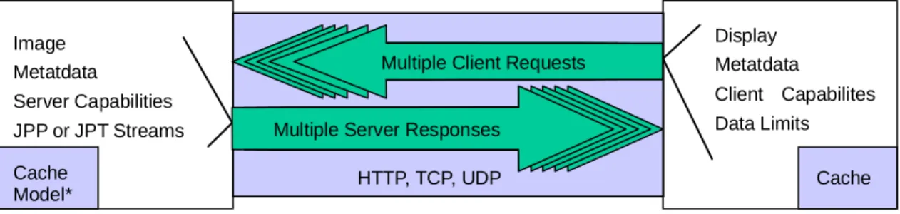
JPIP defines the interactive protocol to achieve the efficient exchange of JPEG 2000 imagery and imagery related data. The protocol defines the Client-Server interactions based on a client request and server response as shown in Figure 1. The client uses a View-Window request to define the resolution, size, location, components, layers, and other parameters for the image and imagery related data that is requested by the client. The server response delivers imagery and imagery related data with precinct-based streams, tile-based streams, or whole images. The protocol also allows for the negotiation of client and server capabilities and limitations. The client may request information about an image as defined in index tables from the server, which enables the client to refine its View-Window request to image specific parameters (e.g., byte range requests). The server’s cache model is based on the capabilities defined by the client and the statefulness of the session.
Figure 1 — JPIP Protocol overview
Cache Client Cache Model* Server HTTP, TCP, UDP *OnlyifState ispresent Image Metatdata Server Capabilities JPPor JPTStreams Display Metatdata Client Capabilites DataLimits Multiple Server Responses
This protocol can be used over several different transports as shown in Figure 2. This standard includes informative annexes on the use of JPIP Protocol over HTTP and TCP, and provides suggestions for other example implementations.
JPIP
IP
TCP UDP
HTTP
Figure 2 — JPIP protocol stack
Provisions have been included for the extension of the JPIP protocol to support the current JPEG 2000 Standards ISO/IEC 15444–3 Motion JPEG 2000 and ISO/IEC 15444–6 Compound Documents and the future parts of JPEG 2000 (currently JP3D, JPSEC, and JPWL).
6.2 Purpose
This International Standard defines the syntax and methods required for both the client and server. Each Annex defines a component that is required to achieve interoperability and functionality between the client and server over several transports. Each Annex may be a requirement of the client, server, or both and are described below.
⎯ Annex A describes the tile based and precinct based streams that are required for both the client and the server. The server is required to produce compliant JPP- and JPT-streams and understand uploaded JPP- and JPT-streams. The client is required to understand and properly decode these streams and is responsible for producing compliant streams when uploading partial imagery to the server.
⎯ Annex B describes the session and cache modelling of a client/server session and is required for both the client and server.
⎯ Annex C defines the client request syntax. The client shall produce compliant versions of this and the server shall be able to understand and respond to all compliant-requests.
⎯ Annex D defines the server response syntax. The server shall produce compliant versions of this and the client shall be able to understand compliant responses.
⎯ Annex E defines syntax and methods to upload a partial image for systems which use JPIP for upload. ⎯ Annex F, Annex G, and Annex H define the methods and procedures for JPIP client/server interactions
over several different transport protocols.
⎯ Annex I defines the indexing information syntax contained in a JPEG 2000 box that can be used by a client and server to more efficiently access imagery and imagery related data.
⎯ Annex J describes several examples of using this Recommendation | International Standard for several different applications.
7 Common BNF definitions
7.1 GeneralThe following BNF definitions are used and referenced throughout this International Standard.
7.2 Integers and character sets
LOWER = "a" | "b" | "c" | "d" | "e" | "f" | "g" | "h" | "i" | "j" | "k" | "l" | "m" | "n" | "o" | "p" | "q" | "r" | "s" | "t" | "u" | "v" | "w" | "x" | "y" | "z"
UPPER = "A" | "B" | "C" | "D" | "E" | "F" | "G" | "H" | "I" | "J" | "K" | "L" | "M" | "N" | "O" | "P" | "Q" | "R" | "S" | "T" | "U" | "V" | "W" | "X" | "Y" | "Z"
ALPHA = LOWER | UPPER
DIGIT = "0" | "1" | "2" | "3" | "4" | "5" | "6" | "7" | "8" | "9" NZDIGIT = "1" | "2" | "3" | "4" | "5" | "6" | "7" | "8" | "9" HEXDIGIT = DIGIT | "A" | "B" | "C" | "D" | "E" | "F" | "a" | "b" | "c" | "d" | "e" | "f" UINT = 1*DIGIT
NONZERO = 0*"0" NZDIGIT 0*DIGIT UINT-RANGE = UINT ["-" [UINT]] UFLOAT = 1*DIGIT ["." 1*DIGIT]
ENCODED-CHAR = "%" HEXDIGIT HEXDIGIT CR = 0x0D
LF = 0x0A CRLF = CR LF
LWS = Optional linear white space UUID = 16(HEXDIGIT)
TOKEN= 1*(ALPHA | DIGIT | "/" | "." | "_")
[Editor’s note: Should it be "\" | "/" | "." | "_" – i.e. include forward and backward slash?]
UINT-RANGE specifies a range of integer values. The first integer in the range specifies the beginning of the range. If two values are specified, the first and second values specify the inclusive beginning and ending limits to the range. If only the first value and the “-“ character are specified, the range includes all values greater than or equal to the first value.
A numerical value immediately preceding a BNF element refers to a repetition of the parameter that follows the number for the number of times given by the numerical value, with no intervening spaces between each occurrence.
The construct “1#” refers to one or more repetitions of the parameter that follows, each occurrence of which is separated by a comma.
The construct “n*” refers to a repetitions of the parameter that follows with no intervening spaces between each occurrence, where there are at least n occurrences of that parameter. n may be zero.
The construct “1$” refers to one or more repetitions of the parameter that follows, each occurrence of which is separated by a semicolon.
The construct “n*m” refers to a repetition of the parameters that follows with no intervening spaces between each occurrence, where there are at least n occurrences and no more than m occurrences.
The construct “0*” means zero or more repetitions of the parameter that follows, with no intervening spaces between each occurrence.
7.3 File format elements
compatibility-code = 4(ALPHA | DIGIT | "_" | ENCODED-CHAR) box-type = 4(ALPHA | DIGIT | "_" | ENCODED-CHAR)
box-type-list = "*" | 1#(box-type) box-desc = box-type ["[" UINT "]"]
box-type specifies the four characters of the box type. For each character in the box type, if the character is alpha-numeric (A..Z, a..z or 0..9), the character is written directly into the string. If the character is a space (0x20), then that character shall be encoded as the underscore character (“_”). For any other character, a 3-character string is written in its place, consisting of an percent 3-character (“%”) followed by two hexadecimal digits representing the value of the character from the box type in hexadecimal. The compatibility-code is encoded the same way that a box-type is encoded.
box-type-list specifies a list of box types. If the value of a box-type-list field is “*”, then the field refers to all box types.
box-desc describes a specific box at a given level of the logical target, by specifying the type of that box and the count of how many boxes of that type are found before the box to be described. For example, the 3rd association box at a given level in the logical target would be described as “asoc[2]”. If the count value is 0, the count may be omitted. For example, the first XML box may be described as either “xml_[0]” or “xml_”.
Annex A
(normative)
The JPP-stream and JPT-stream media types
A.1 Introduction
JPP-stream and JPT-stream are media types useful for presenting JPEG 2000 codestreams and file format data in an arbitrary order. Each media type consists of a concatenated sequence of messages, where each message contains a portion of a single data-bin preceded by a message header. Data-bins contain portions of a JPEG 2000 compressed image representation, such that it is possible to construct a stream that completely represents the information present in a JPEG 2000 file or codestream. Each message is completely self-describing, so that the sequence of messages may be terminated at any point and messages may be re-ordered subject to minimal constraints without losing their meaning. For these reasons, JPP-stream and JPT-stream media types are useful for JPIP servers and the JPIP protocol is designed with these media types particularly in mind. This Annex defines the JPP-stream and JPT-stream media types without reference to the JPIP protocol.
A.2
Message Header Structure
A.2.1 GeneralEach message represents a portion of exactly one data-bin. The message header consists of a sequence of variable-length byte-aligned segments (VBAS). Each VBAS consists of a sequence of bytes, all but the last of which has a most significant bit (bit 7) of 1, as seen in Figure A.1. The least significant 7 bits of each VBAS are concatenated to form a bit stream which is used in different ways for different VBAS’s.
MSB LSB
1 X X X X X X X • • •
1 X X X 0 X X X X 1 X X X X X X X X X X X X X X
Figure A.A1 — VBAS structure
The message header serves to identify the particular data-bin and byte range which is represented by the message body. Message headers can take an independent form and a dependent form. The independent form is a long form where the message headers are completely self-describing; their interpretation is independent of any other message headers. The optional shorter dependent form message headers make use of information in the headers of previous messages; their decoding is dependant on the previous message. Applications may choose to use the long form message headers; these messages can be rearranged in any arbitrary order. Alternatively, applications may use the shorter form message headers that do depend on previous message headers; these are shorter messages but will create erroneous results if the messages are not arranged in the correct sequence when decoded. It is an application decision whether or not the sequence ordering of received messages can be assumed to be reliable, and if so, whether to make use of the shorter form message headers.
The message header consists of the following VBAS’s (optional VBAS’s identified by the use of square brackets):
The existence of the Class and CSn VBASs are determined by examining the Bin-ID VBAS. The existence of the Aux VBAS is determined by the Class VBAS or the previous Class VBAS, if there is no Class VBAS in the current message header.
MSB LSB
a b b c d d d d a d d d d d d d a d d d d d d d • • •
Figure A.A2 — Bin-ID VBAS structure
The Bin-ID VBAS serves several roles. Bits 6 & 5 of the first byte of the Bin-ID VBAS, labelled ‘b’ in Figure A.2, indicate whether the Class and CSn VBASs are present in the message header.
Bit 4 of the first byte of the Bin-ID VBAS, labelled ‘c’ in Figure A.2, indicates whether or not this message contains the last byte in the associated data-bin: ‘0’ means it is not the last byte in the data-bin; ‘1’ indicates that it is the last byte in the data-bin. Receiving a message with this bit set allows determination of the length of the complete data-bin, although it does not imply that the complete JPP-stream or JPT-stream contains sufficient messages to assemble all of the bytes from that data-bin.
The remaining 4 bits of the first byte and the 7 low order bits of any remaining bytes in the Bin-ID VBAS (labelled `d’ in Figure A.2) form an “in-class identifier”, which is used to uniquely identify the data-bin within its class, in the manner described in Annex A.2.3.
Table A.A1 — Bin-ID Additional VBAS indication Indicator
Bits ‘bb’
Meaning
00 Prohibited.
01 No Class or CSn VBAS is present in message header
10 Class VBAS is present but CSn is not present in message header
11 Class and CSn VBAS are both present in the message header.
The Class VBAS, if present, provides a message class identifier. The message class identifier is a non-negative integer, formed by concatenating the least significant 7 bits of each byte of the VBAS in big-endian order. If the Class VBAS is not present, the message class identifier is unchanged from that associated with the previous message. If the Class VBAS is not present and there is no previous message, the message class identifier is 0. Valid message class identifiers are described in Annex A.2.2.
The CSn VBAS, if present, identifies the index (starting from 0) of the codestream to which the data-bin belongs. The codestream index is formed by concatenating the least significant 7 bits of each byte of the VBAS in big-endian order. If the CSn VBAS is not present, the codestream index is unchanged from the previous message. If CSn VBAS is not present and there is no previous message, the codestream index is 0. The Msg-Offset and Msg-Length VBAS’s each represent integer values, formed by concatenating the least significant 7 bits of each byte in the VBAS in big-endian order. The Msg-Offset integer identifies the offset of the data in this message from the start of the data-bin. The Msg-Length integer identifies the total number of bytes in the body of the message.
An auxiliary VBAS may be present. Its presence, and meaning if present, are determined by the message class identifier found within the Bin-ID VBAS, as explained in the Annex A.2.2. If present, the auxiliary VBAS represents an integer, formed by concatenating the least significant 7 bits of each byte in the VBAS in big-endian order.
A.2.2 Message Class Identifiers
The message class identifiers defined by this document are the non-negative integers shown in the Table A.2. The interpretation of the data-bin classes to which they refer is described in Annex A.3. All other values of message class identifier are reserved, and the associated messages should be skipped by decoders not recognizing the value.
Class identifiers are chosen such that an auxiliary VBAS is present if and only if the identifier is odd. This property allows unrecognized message headers to be correctly parsed and the contents skipped.
Table A.A2 — Class identifiers for different data-bin message classes Class
Identifier
Message Class Data-Bin Class Stream Type
0 Precinct data-bin message Precinct data-bin JPP-stream only
1 Extended precinct data-bin message Precinct data-bin JPP-stream only
2 Tile header data-bin message Tile header data-bin JPP-stream only
4 Tile data-bin message Tile data-bin JPT-stream only
5 Extended tile data-bin message Tile data-bin JPT-stream only
6 Main header data-bin message Main header data-bin JPP- and JPT-stream
8 Metadata-bin message Metadata-bin JPP- and JPT-stream
Extended precinct data-bin messages have exactly the same interpretation as non-extended precinct data-bin messages and they refer to exactly the same precinct data-bins. The extended precinct messages include an auxiliary VBAS which identifies the number of complete packets (quality layers) which would be available for the precinct if the bytes in this message were combined with all previous bytes of the same precinct. If this message also contains the last byte of the data-bin, the auxiliary VBAS indicates the total number of quality layers associated with the precinct in the original codestream. Otherwise, the auxiliary VBAS indicates the quality layer to which the byte immediately following the last byte in the message belongs. The information in the auxiliary VBAS may be useful to certain clients.
Extended tile data-bin messages have exactly the same interpretation as non-extended tile data-bin messages and they refer to exactly the same tile data-bins. The extended tile messages include an auxiliary VBAS which identifies the number of complete resolutions starting from the lowest resolution which would be available for all components in the tile if the bytes in this message were combined with all previous bytes of the same tile. Thus the value 1 is used when the lowest resolution is complete, and the value is the number of wavelet transform levels plus one when all resolutions have been delivered. Because resolutions do not necessarily appear in order in a tile some resolutions above the value given in the VBAS may have been completed, but this cannot be determined from the message header. The information in the auxiliary VBAS may be useful to certain clients.
A.2.3 In-class identifiers
The least significant 4 bits of the first byte and the least significant 7 bits of all other bytes from the Bin-ID VBAS are concatenated in big-endian order to form a single word, having 7k-3 bits, where k is the number of bytes in the VBAS. This word represents an unsigned integer which serves to uniquely identify the data-bin within its class and codestream. Annex A.3 provides a description of the various data-bin classes, along with the corresponding in-class identifiers.
A.3 Data-bins
A.3.1 IntroductionData-bins contain portions of a JPEG2000 file or codestream data. These may be based on imagery elements, such as precint-based data, tile-based data, and headers. They may also be based on metadata. Whatever the content of a data-bin, each data-bin is treated as an individual bit-stream.
A.3.2 Precinct data-bins A.3.2.1 Precinct data-bin format
Precinct data-bins appear only within the JPP-stream media-type. Each precinct data-bin corresponds to a single precinct within a single codestream. The in-class identifier, I, uniquely identifies the precinct within its codestream. It is defined by
I=t+(c+s×num_components)×num_tiles
where t is the index (starting from 0) of the tile to which the precinct belongs, c is the index (starting from 0) of the image component to which the precinct belongs, and s is a sequence number which identifies the precinct within its tile-component. Within each tile-component, precincts are assigned contiguous sequence numbers, s, as follows. All precincts of the lowest resolution level (that containing only the LL subband samples) are sequenced first, starting from 0, following a raster-scan order. The precincts from each successive resolution level are sequenced in turn, again following a raster-scan order within their resolution level.
It follows that a precinct identifier of 0 refers to the upper left hand precinct from the LL subband of image component 0 in tile 0.
Each precinct data-bin corresponds to the string of bytes formed by concatenating all codestream packets, complete with all relevant packet headers, which belong to the precinct. It is conceivable that packet headers will be packed into PPM or PPT marker segments which shall then belong to main header or tile header data-bins, in which case the precinct data-bin would hold only packet bodies. In any event, the precinct data stream should coincide with the contiguous segment of bytes that would be found within a JPEG 2000 codestream having one of the layer-subordinate progression sequences (CPRL, PCRL or RPCL).
A.3.2.2 Precinct data-bin example (informative)
Layer 0 Layer 1 Layer 2 Layer 3 56 136 220 317 Offset = 136 Length = 181 Offset = 107 Precinct data-bin 3 (Case A) (Case C) Length = 84 Message body (Case B) Length = 165 Message body Message body Offset = 136 0 Byte
Figure A.A3 — Example precinct data-bin
For Case A, B and C, the message header is shown below, based on the extended and non-extended precinct data-bin message structures. The underlined data denotes the auxiliary VBAS to identify the number of layers which are completed by the message.
(Case A)
Non-extended header: 00100011 01101011 10000001 00100101 xxxxxxxx …
The initial 0 bit indicates only one byte is used in the Bin-ID VBAS. The next two bits (“01”) indicate that no Class or CSn VBAS is present. The next “0” bit indicates that the data-bin is not completed by this message. The remaining bits of the first byte (“0011”) indicate that the bin-ID is 3. The first bit of the second byte indicates that there is only one byte used in the Msg-Offset VBAS. The next 7 bits (“1101011”) mean that the offset is 107. The first bit of the 3rd byte indicates that both this byte and at least the next byte are part of the Msg-Length VBAS. The 0 bit starting the 4th byte indicates that it is the last byte of the Msg-Length VBAS. Thus all the low order bits from the 3rd and 4th bytes are concatenated to determine the length. In this case, “0000001 0100101” = 165. Extended header: 01000011 00000001 01101011 10000001 00100101 00000011 xxxxxxxx … (Case B) Non-extended header: 00100011 10000001 00001000 01010100 xxxxxxxx … Extended header: 01000011 00000001 10000001 00001000 01010100 00000011 xxxxxxxx … (Case C) Non-extended header: 00110011 10000001 00001000 10000001 00110101 xxxxxxxx … Extended header: 01010011 00000001 10000001 00001000 10000001 00110101 00000100 xxxxxxxx …
Note that since the return data contains the last byte of the data-bin in Case C, the Bin-ID VBAS indicates that it is a "completed" message.
A.3.3 Tile header data-bins
Tile header data-bins appear only within the JPP-stream media type. For data-bins belonging to this class, the in-class identifier holds the index (starting from 0) of the tile to which the data-bin refers. This data-bin consists of markers and marker segments for tile n. It shall not contain an SOT marker segment. Inclusion of SOD markers is optional. This data bin may be formed from a legal codestream, by concatenating all marker segments except SOT and POC in all tile-part headers for tile n.
A.3.4 Tile data-bins
Tile data-bins shall be used only with the JPT-stream media type. For data-bins belonging to this class, the in-class identifier is the index (starting from 0) of the tile to which the data-bin belongs. Each tile data-bin corresponds to the string of bytes formed by concatenating all tile-parts belonging to the tile, in order, complete with their SOT, SOD and all other relevant marker segments.
A.3.5 Main header data-bin
Both JPP- and JPT-stream media types use the main header data-bin. For data-bins belonging to the codestream main header class (completed or non-completed variations), the in-class identifier shall be 0. This data-bin consists of a concatenated list of all markers and marker segments in the main header, starting from the SOC marker. It contains no SOT, SOD or EOC markers.
A.3.6 Metadata-bins
A.3.6.1 Introduction to metadata-bins
Both JPP- and JPT-stream media types use metadata-bins. Metadata-bins are used to convey metadata from the logical target that contains the codestream or codestreams whose elements may be referenced by other data-bins associated with the JPP-stream or JPT-stream. For the purpose of this document, the term “metadata” refers to any collection of “boxes” from a JPEG 2000 family file. The codestream index shall be ignored in any message which has the metadata-bin class identifier.
Unlike the numerical ID’s used for other types of data-bins, metadata-bin ID’s do not map algorithmically to some file format construct or byte offset. The server is free to choose any numeric ID for any particular metadata bin. The one and only one exception of this is that the metadata-bin containing the root of the logical target shall be given the ID of 0.
Note: The mechanism for assignment is implementation dependent, however, it is an informative suggestion that servers assign bin-ID’s using consecutive numbers.
A.3.6.2 Division of a logical target containing a JPEG 2000 file into metadata-bins
All metadata could conceivably be included in metadata-bin 0. In this case, all boxes from the logical target would belong to metadata-bin 0, appearing in their original order. Since JPEG 2000 family file formats consist of nothing but a sequence of boxes, this effectively means that metadata-bin 0 would consist of the entire logical target. More generally, however, it is useful to break the logical target into pieces that can be transmitted in a manageable fashion. This allows image servers to deliberately omit portions of the logical target that are not currently required by a client. To this end, JPIP defines a new special box type, known as the “Placeholder box.” The Placeholder box serves to identify the size and type of a box from the logical target, while pointing to another data-bin that holds that box’s contents. Placeholders are also able to represent codestreams from the logical target. This is particularly significant in view of the fact that the compressed data represented by any given codestream may be delivered incrementally via the other data-bin types (header data-bins and precinct data-bins or tile data-bins).
Formally, metadata-bin 0 consists of all boxes from the logical target, appearing in their original order, with the exception that a placeholder may replace any given box. The Placeholder box contains the original header of the box that has been replaced, together with the identifier of the metadata-bin that holds that box’s contents, not including the header itself. Every metadata-bin, other than metadata-bin 0, shall consist of the contents of
some box, whose header appears in the placeholder that references that data-bin. These box contents may themselves include sub-boxes, any of which may be replaced by further placeholders.
The following colour scheme will be used for metadata-bin example illustrations (Figure A.4):
Metadata-bin
Complete boxes (including box headers) Box contents (no box headers)
Placeholder boxes (replacing the original box from the file)
Figure A.A4 — Metadata-bin example colour scheme As an example, consider a simple JP2 file with the following box structure (Figure A.5):
'jp2h' box 'ihdr' box 'colr' box 'xml ' box 'ftyp' box 'jp ' box 'jp2c' box
Figure A.A5 — A sample JP2 file
This file may be divided up into three metadata-bins: one to represent the top-level of the original file (data-bin 0); one to represent the JP2 Header box; and one to represent the codestream. This division is shown in Figure A.6.
Metadata-bin 0 'jp ' box
Placeholder for ' jp2h' box: original 'jp2h' box header metadata-bin ID=1 Placeholder for 'jp2c' box: original 'jp2c' box header metadata-bin ID=2 'ftyp' box Metadata-bin 1 'ihdr' box 'colr' box 'xml ' box Metadata-bin 2 'jp2c' box contents
Figure A.A6 — A sample JP2 file divided into three metadata-bins
While the contents of any metadata-bin shall be the contents of the box or file represented by that bin, the actuall data contained in those contents may conceptually vary depending on the type of box. For example, in Metadata-bin 1 in Figure A.6, representing the contents of the JP2 Header box, the contents of that box is literally a series of other complete boxes, as the JP2 Header box is a superbox. No data other than the series of those complete boxes may be found within Metadata-bin 1, as there is no other data in the JP2 Header box.
In contrast, the data inside Metadata-bin 2 is the raw contents of the Contiguous Codestream box, with no box headers, because that box is not a superbox.
One point of particular interest to note from the example in Figure A.6 is that access to codestream data may be provided in two ways. The second placeholder bin is used to replace the contiguous codestream box (jp2c) in the original file. It identifies metadata-bin 2 as holding the original contents of this box, i.e., the raw codestream itself. The placeholder may also provide a codestream identifier. Any data-bins belonging to the main header, tile header, precinct or tile data-bin classes, having this same codestream identifier, convey compressed data associated with the same codestream as that found in metadata-bin 2. For convenience of description in this document, the terms “raw codestream” and “incremental codestream” will be used to distinguish between the representation which may appear in a metadata-bin (raw) and the representation which may appear in header, precinct and tile data-bins (incremental).
In general, placeholders that reference codestream data may do so either by referencing a separate metadata-bin (raw codestream), or by providing a codestream identifier (incremental codestream), or both. Even if both methods are provided, the JPP-stream or JPT-stream data available at a client or image-rendering agent might only have the contents of the raw codestream, or only have data from the incremental codestream. Moreover, if both the raw and incremental versions of the same codestream are available, there is no guarantee that the two representations will have compatible coding parameters. Only the reconstructed image samples associated with the two representations are guaranteed to be consistent.
It is also possible to use Placeholder boxes to associate multiple codestreams with a single original box. The interpretation of such an association is dependent upon the box being replaced. Further discussion of this topic appears in A.3.5.4.
In the simple example of Figure A.5, Placeholder boxes appear only at the top-level of the file, in metadata-bin 0. As already noted, however, placeholders may be used to replace any box, in any metadata-bin. This allows complex files to be decomposed in hierarchical fashion. As such, a single original file may be encapsulated in a variety of different metadata-bin structures, depending on how placeholders are used. However, a single JPP-stream or JPT-stream shall adopt only one such encapsulation. In client-server applications, the server will generally determine a suitable metadata-bin structure for the file, assigning a unique identifier to the resulting stream, and using the same metadata-bin structure in all communication with all clients which reference this same unique identifier.
When a placeholder relocates a box into a new metadata-bin, the header of that box (LBox, TBox and XLBox fields) is stored, unmodified, in the Placeholder box. If a client or rendering agent needs to map particular boxes to their original file offsets, it may do so using the original box headers that appear in the Placeholder boxes. This information ultimately allows any location in the original file to be mapped to a particular location in a particular metadata-bin, if the contents of that data-bin exist. This is important since some JPEG 2000 family files contain boxes that reference other boxes through their location within the file.
While considerable freedom exists in deciding how best to divide a file into metadata-bins, there is one restriction. Any Placeholder box that appears within a metadata-bin shall replace a top-level box within that data-bin. Equivalently, wherever a sub-box is to be replaced with a placeholder, its immediate containing super-box shall reside within its own metadata-bin. For example, in the sample file shown in Figure A.5, the XML data contained within the JP2 Header box may be placed in a separate data bin from the other boxes. This allows a server to deliver only those data-bins that are actually required for decoding and display of the image, unless XML data is explicitly requested. A suitable data-bin structure is shown in Figure A.7.
Metadata-bin 0 'jp ' box
Placeholder for 'jp2h' box: original 'jp2h' box header metadata-bin ID=1 Placeholder for 'jp2c' box: original 'jp2c' box header metadata-bin ID=2 'ftyp' box Metadata-bin 1 'ihdr' box 'colr' box Metadata-bin 2 'jp2c' box contents Metadata-bin 3 'xml ' box contents
Placeholder for 'xml ' box: original 'xml ' box header metadata-bin ID=3
Figure A.A7 — A superbox with a referenced metadata-bin
It would not be legal, however, for the JP2 Header box to be left in metadata-bin 0, as shown in Figure A.8:
Metadata-bin 0 'jp ' box
Placeholder for 'jp2c' box: original 'jp2c' box header metadata-bin ID=2 'ftyp' box Metadata-bin 1 'xml ' box contents Metadata-bin 2 'jp2c' box contents 'jp2h' box 'ihdr' box 'colr' box
Placeholder for 'xml ' box: original 'xml ' box header metadata-bin ID=1
This division of the file is not permitted. If the XML box is to be separated into its own metadata-bin, the JP2 Header box ('jp2h') must also be separated into its own metadata-bin
Figure A.A8 — An illegal division of the file into metadata-bins
NOTE An equivalent way to express this same restriction is as follows. Wherever a placeholder replaces a sub-box, a placeholder shall also replace its containing box. This restriction ensures that it is always possible for a client or rendering agent to recover the lengths and locations of the original boxes within the file, even if some of the boxes are not understood by the client.
In addition to providing the original contents of a box in a separate metadata-bin, JPP- and JPT-streams are also permitted to provide alternate representations of the box, which did not explicitly appear within the original file. These alternate representations are known as “stream equivalents.” For example, the original file might contain a Cross-reference box whose fragment list box collects one or more fragments of the file to reconstitute a Colourspace Specification box. While a client or rendering agent should be able to follow the relevant file pointers to reconstruct the Colourspace Specification box, a more convenient JPP- or JPT-stream representation might contain a placeholder which references a data-bin containing the Colourspace Specification box as a stream equivalent. To do this, the placeholder includes a box header for the stream equivalent, together with the identifier of the metadata-bin that holds the contents of the stream equivalent box. The following example (shown in Figure A.9) illustrates the use of stream equivalents for Cross-reference boxes. In this case, the data-bin that holds the stream-equivalent contents is also referenced as holding the original contents of another box. While this is likely to be a common situation where the original file contained
cross-reference boxes, there is no need for the stream-equivalent to point to a metadata-bin that is connected to the original file hierarchy. The stream equivalent box’s contents may be created from scratch or they may refer to content which originally existed within other files. This allows Cross-reference boxes whose fragment list references other files or URLs to be fully encapsulated within a single JPP- or JPT-stream.
Metadata-bin 1 Metadata-bin 0
'jp ' box 'ihdr' box
Placeholder for 'colr'box:
original 'colr' box header metadata-bin ID=3 Placeholder for 'jp2h' box:
'jp2h' box header metadata-bin ID=1 Placeholder for 'jp2h' box: 'jp2h' box header metadata-bin ID=2
Metadata-bin 2 'ihdr' box
Placeholder for 'cref' box original 'cref' box header metadata-bin ID=4
stream-equivalent 'colr' box header metadata-bin ID=3
Metadata-bin 3 'colr' box contents
Metadata-bin 4 'cref' box contents: file offset 'ftyp' box
Figure A.A9 — Example of the use of stream equivalents
Stream equivalents may be used in any situation where the server can create an alternate form of the contents of a box that provide some benefit to the client; they are not just for providing access to explicitly cross-referenced data.
In addition to pointing to actual or equivalent box data, a placeholder box can point to one or more codestreams where the replaced box is equivalent to those codestreams. For example, the Contiguous Codestream box may be replaced by a placeholder box that references the ID of the incremental codestream contained within that Contiguous Codestream box. Another example would be to replace the Chunk Offset box in a Motion JPEG 2000 file with a placeholder that specifies an array of codestream ID’s. Those codestream ID’s refer to the codestreams that are pointed to by the Chunk Offset box.
A.3.6.3 Placeholder box format
Figure A.10 shows the format of a Placeholder box, including the box header (unlike the definition of most boxes in Annex I and other parts of this standard); it is specified this way to emphasise that the use of the length field in the box header for a Placeholder box is more restrictive than for other boxes.
Minimal placeholder box
Placeholder box with a st ream equivalent representation Placeholder box with an associated single codestream
Placeholder box with multiple associated codestreams Possible future extensions
LBox TBox Flags OrigID EquivID CSID NCS
OrigBH EquivBH
LBox: This is the standard 4-byte big-endian length field for a box. The value shall not be 1 for a Placeholder box, meaning that the XLBox field shall not be present.
TBox: This is the standard 4-byte box type field for a box. The type value for a Placeholder box shall be ‘phld’ (0x7068 6c64).
Flags: This field specifies what elements of the Placeholder box contain valid data. This field is encoded as a 4-byte big-endian integer. Legal values for the Flags field are specified in Table A.3.
OrigID: This field specifies the metadata-bin ID of the bin containing the contents of the original box represented by this Placeholder box. It is encoded as an 8-byte big-endian unsigned integer.
OrigBH: This field specifies the original header (LBox, TBox and XLBox, as needed) of the original box referenced by this Placeholder box. The length of this field is 8 bytes if the original box header’s LBox field is not equal to 1 and 16 bytes otherwise.
EquivID: This field specifies the metadata-bin ID of the bin that contains a stream-equivalent form of the contents of this box. This field is encoded as an 8-byte big-endian unsigned integer.
EquivBH: This field specifies the header of the stream-equivalent box (LBox, TBox and XLBox as needed) of the box referenced by this Placeholder box. The length of this field is 8 bytes if the equivalent box header’s LBox field is not equal to 1 and 16 bytes otherwise.
CSID: This field specifies the ID of the first codestream associated with the replaced box. This is the ID that is associated with all header, precinct and/or tile data-bins used to incrementally communicate the contents of the first codestream associated with the replaced box. This field is encoded as an 8-byte big-endian unsigned integer.
NCS: This field specifies the number of codestreams in the array of codestreams that is equivalent to the replaced box. The codestream ID values of these codestreams run contiguously from the value specified by the CSID field. This field is encoded as a 4-byte big-endian unsigned integer.
ExtendedBoxList: This field is not specifically shown in Figure A.10. The NCS field may be followed by a sequence of boxes containing extended information from the server. The existence of any box following the NCS field shall be specified through a bit in the Flags field. However, no extended boxes, nor any additional bit flags, are defined by this International Standard. Clients shall ignore any box in ExtendedBoxList that is not understood.
Table A.A3 — Legal values for the Flags field of a Placeholder box
Value Meaning
yyyy yyyy yyyy yyyy yyyy yyyy yyyy xxx1 Access is provided to the original contents of this box through the metadata-bin specified in the OrigID field yyyy yyyy yyyy yyyy yyyy yyyy yyyy xxx0 No access is provided to the original contents of this box,
and the value of the OrigID field shall be ignored
yyyy yyyy yyyy yyyy yyyy yyyy yyyy xx1x A stream-equivalent box is provided, whose contents are in the metadata-bin specified by the EquivID field.
yyyy yyyy yyyy yyyy yyyy yyyy yyyy xx0x No stream-equivalent box is provided, and the value of any EquivID and EquivBH fields shall be ignored
yyyy yyyy yyyy yyyy yyyy yyyy yyyy 01xx Access to the image represented by this box is provided by a single incremental codestream, which is identified by the CSID field. The value of the NCS field shall be treated as if was set to "1" regardless of the actual value of that field.
yyyy yyyy yyyy yyyy yyyy yyyy yyyy 11xx Access to the image represented by this box is provided by one or more incremental codestreams, as specified by the CSID and NCS fields.
Table A.A3 — Legal values for the Flags field of a Placeholder box
Value Meaning
yyyy yyyy yyyy yyyy yyyy yyyy yyyy x0xx This placeholder does not provide access to an image
representing the original box as an incremental codestream; the CSID and NCS fields shall be ignored.
Other values Reserved for ISO use
A bit value of “x” in Table A.3 indicates that the specified value includes cases where that bit is set to either “1” or “0”. Bits indicated as “y” are unused by this standard and shall be set to 0 by servers and ignored by clients. Not all of the fields defined in for a Placeholder box need appear in every Placeholder box. As suggested by the arrows in Figure A.10, if no box equivalent or incremental codestream ID is provided, the box may be terminated at the end of the OrigBH field. Similarly, if no incremental codestream ID is provided, the box may be terminated at the end of the EquivBH field, and if no more than one incremental codestream ID is provided, the box may be terminated at the end of the CSID field.
A.3.6.4 Referencing of incremental codestreams with placeholders
Wherever header, precinct or tile data-bins exist, their codestream ID shall appear in a Placeholder box within an appropriate metadata-bin. The only exception to this requirement is for unwrapped JPEG 2000 codestreams, which are not embedded within a JP2-family file format.
The codestream ID values that appear within the relevant Placeholder box shall conform to any requirements imposed by the containing file format. For example, JPX files formally assign a sequence number to each codestream that appears at the top level of the file, either through a Contiguous Codestream box or a Fragment Table box. The first top-level codestream in the logical target shall have a codestream ID of 0; the next shall have a codestream ID of 1; and so forth.
Placeholders that reference multiple codestream ID’s may be used only where the meaning of those codestreams is well defined by the type of the box that is being replaced. This International Standard defines only two such box types, for use with Motion JPEG 2000 (MJ2) files. Specifically, either the chunk offset box (‘stco’) or the chunk large offset box (‘co64’) may be replaced by a Placeholder box which identifies multiple codestream ID’s.
A.3.6.5 Using Placeholder boxes with MJ2
Each video track in an MJ2 file contains exactly one chunk offset box (either ‘stco’ or ‘co64’) that, in combination with the sample to chunk box (‘stsc’), serves to identify the locations of all of the contiguous codestream boxes that belong to the video track. If the chunk offset box is replaced by a placeholder that provides one or more codestream ID’s, there shall be exactly one codestream ID for each contiguous codestream box in the video track. If the visual sample entry box (‘mjp2’) identifies a field count of 2, there shall be 2N codestream ID’s in the range provided by the Placeholder box, where N is the number of video samples (i.e., N is the number of frames). Otherwise, there shall be only N codestream ID’s in the range provided by the Placeholder box. The codestream ID’s shall be sequenced by sample number (frame number) and by field number within each sample.
NOTE For MJ2 files in a JPP-stream or a JPT-stream representation, there is no need for the stream to contain the contents of the original chunk offset box, the sample to chunk box (‘stsc’), or the sample size box (‘stsz’). This indexing information can be regenerated if needed if the stream representation is converted to an MJ2 file.
A.4
Conventions for parsing and delivery of JPP-Stream and JPT-Streams
(informative)
Placeholder boxes create additional flexibility and some potential ambiguity for both clients and servers in how they parse or deliver JPP- and JPT-streams. A server may choose to partition original boxes from a JP2-family file into metadata-bins using any of a wide range of strategies, by introducing Placeholder boxes at appropriate points. The server shall do this in a consistent way so that the data-bins associated with a JPP- or JPT-stream have the same nominal contents for all clients which access the same logical target (possibly qualified by a unique target ID), whenever they access it.
More significantly, however, Placeholder boxes allow servers to construct a single JPP- or JPT-stream whose data-bins provide multiple alternate representations of the same original content. This can happen when a streaming equivalent is identified within a placeholder, and/or when an incremental codestream ID is identified within a placeholder. In these cases, an original JP2 box might be made available in a metadata-bin, while also being made available as a stream equivalent in yet another metadata-bin, and/or also being made available as an incremental codestream via header, precinct or tile data-bins. While servers might distribute the contents of all data-bins that represent an original box, for efficiency reasons servers would be expected to distribute only sufficient information to convey the original content, unless explicitly asked to distribute redundant data-bins. Client-side parsers of JPP- or JPT-streams, when confronted with multiple representations of an original box, might choose to ignore all but one of the representations. The expected client convention should have a significant impact on which metadata-bins the server chooses to actually send to a client.
In view of this, this International Standard recommends the following conventions:
⎯ Unless a server has reason to believe otherwise, it shall assume that the client parser will parse a stream equivalent box in preference to the original box if the presence of both box types has been signalled to the client by placeholders.
⎯ Unless a server has reason to believe otherwise, it shall assume that the client parser will use the incremental codestream representation (header, precinct or tile data-bins) in preference to a raw codestream if the presence of both box types has been signalled to the client by placeholders.
A.5
Conventions for JPP-Stream or JPT-Stream Interoperability (informative)
This convention describes the exchange file format for JPP-Stream and JPT-Stream, herein termed jpp-file and jpt-file respectively. Such a file may contain the received JPEG2000 data from a JPIP session (the client’s cache for example), or a subset thereof. It is possible for another JPIP client to read and use this file because JPP-Stream and JPT-Stream are self-describing media types.
These files are formed by concatenation of JPT-Stream or JPP-Stream messages. For example, they may be formed by the simple concatenation of all such messages received by a client in a single session or from multiple sessions. An improved situation would be where clients generated a legal JPT-Stream or JPP-stream using a single Message Header and Message per data-bin.
It is recommended that the “.jpp” and “.jpt” extensions be used for these files and, if appropriate, that the file name includes a reference to a relevant JPIP target token or target-id token.
This convention does not specify the implementation or structure of the JPIP Cache for a client. For example, a client may use a database to serve as its implementation of the cache function rather than a file-based cache system.
Annex B
(normative)
Sessions, Channels, Cache Model and Model-sets
B.1
Requests Within a Sessions vs. Stateless Requests
The JPIP protocol makes a clear distinction between two different types of requests: stateless requests and requests which belong to a session.
The purpose of sessions is to reduce the amount of explicit communication required between the client and server. Within a session, the server is expected to remember client capabilities and preferences supplied in previous requests so that this information need not be sent in each and every request. Even more importantly, the server would typically keep track of the information it has already sent to the client in response to previous requests, so that this information need not be re-transmitted in response to future requests. Unless explicitly instructed otherwise, the server may assume that the client caches the responses to all requests issued within a session, and may model the client's cache, sending only those portions of the compressed image data or metadata which the client does not already have in its cache.
Stateless requests are not associated with any session and so shall be entirely self-contained. It should be noted that the term “stateless” applies only to the server, not the client. As for sessions, the client should generally cache the responses from previous requests associated with the same logical target. Clients that issue multiple stateless requests for the same target should generally include information about their cache contents with each request, so as to avoid the transmission of redundant data. Thus, the benefits of sessions are smaller, less complex requests and/or less redundant response data from the server. The benefit of stateless communication is that the server need not maintain state information between requests; usually, this means that the same host need not ultimately serve all requests for a single target image that emanate from a single client.
B.2 Channels
and
Sessions
Associated with each session are the following elements:
⎯ One or more logical targets (usually image files), whose content does not change over the session. ⎯ A single image data return type for each logical target associated with the session.
⎯ For each logical target associated with the session, a model of the client’s cache contents shall be maintained wherever the data return type is one of “jpp-stream” or “jpt-stream”. Note, however, that this model need not perfectly reflect the actual state of the client’s cache. Rules governing the maintenance of cache models are outlined in B.3.
⎯ One or more JPIP channels. Clients may generally open multiple channels within the same session. Each JPIP channel may be associated with a separate underlying transport channel (e.g., a separate TCP connection), although this might not be the case. Multiple channels allow clients to issue simultaneous requests for multiple image regions, with the expectation that the server will respond to these requests concurrently. Channels also allow for intelligent bandwidth allocation amongst different types of requests either within a single target image or across multiple targets.
⎯ Where multiple channels are associated with the same logical target, the session cache model applies across all channels. Multiple clients may open JPIP channels within the same session, although this might have undesirable side effects if the channels refer to the same logical target.