OPTIMIZING COGNITIVE EFFICIENCY OF EMOTIV EPOC AND CONTROLLING WHEELCHAIR THROUGH IT.
A Thesis
Submitted to the Department of Electrical and Electronics Engineering of BRAC University by Pritom Chowdhury Student ID: 11121092 S. S Kibria Shakim Student ID: 11121115
In Partial Fulfillment of the Requirements for the Degree
of
Bachelor of Science in Electrical and Electronics Engineering December 2014
DECLARATION
We hereby declare that this thesis is based on the results found by ourselves. Materials of work found by other researcher are mentioned by references. This thesis, neither in whole nor in part, has been previously submitted for any degree.
Signature of Signature of Authors Supervisor --- Dr. Khalilur Rhaman --- Pritom Chowdhury --- S.S Kibria Shakim
ACKNOWLEDGMENTS
We present our sincere gratitude to our Supervisor Dr. Khalilur Rhaman, acting Chairperson,Departmrnt of Computer Science and Engineering, BRAC University for his motivation,support and directions. He has stimulated within us a deep sense of critical thinking and relating knowledge to practical fields through manifold suggessions and directions.
We would also like to thank our co-supervisor Md. Risul Karim,LecturerI Departmrnt of Computer Science and Engineering,BRAC University for helping us with some of the critical portions of the thesis work.
We thank Emotiv EPOC team for helping us with providing various information regarding the device.
ABSTRACT
Brain Computer Interface (BCI) has opened a new era in the field of neuroscience. It has the potentiality to improve the quality of life of severely disabled patients. It allows them to regain the power of moving things by their affective, cognitive and expressive brain activities. Emotiv EPOC head set is a safe and comfortable BCI system which contains a number of advanced electrode sensors. It can detect and process the user’s thoughts, feelings and expressions in real time. A prototype of two wheeler robot is implemented and experimented which was controlled by the thought of human being. In average 72.65% accuracy is observed in the experiment for different aged people from 14 to 30 years old where the accuracy for the physically challenged people is 82% in average. Firstly the prototype software has to be trained by a specific user then it controls a wireless robot by the person’s thought for driving the robot in forward, backward, left and right directions. This robot can be stopped by a specific facial expression which does not need any training. The article also investigated the shortcomings and reviews on the reliability of the cognitive output efficiency of Emotiv EPOC EEG device, based on user comments and related researches. It has extended its possibilities to such an extent that now it has become possible to use BCI in the field of robotics and bio-medical systems. In the recent year the world has experienced some miraculous advancement of BCI due to advancement in the algorithm of EEG data extraction. Moreover, now a day the device architecture is also showing revolutionary development. These devices are efficient enough to be used in robotics but are very costly. It will be very inefficient to release a robotic product for the mass people considering the relatively high cost. Hence a EEG extraction device with law price and satisfactory performance is a need in the current context. This paper contains research works on building BCI based wheel-chair. The electrical wheelchair has been designed from the scratch and has been integrated with the BCI based device Emotiv EPOC. The paper describes how a wheelchair can be designed so that it works efficiently with the medium category EEG data extraction devices.
TABLE OF CONTENTS Page TITLE………...…i DECLARATION…...…ii ACKNOWLEDGEMENTS...iii ABSTRACT………...iv TABLE OF CONTENTS...…....v LIST OF TABLES...vii LIST OF FIGURES...viii CHAPTER I. INTRODUCTION 1.1 An Overview ………..1 1.2 Motivation………...3 1.3 Architecture………...4
CHAPTER II. IMPLEMENTATION 2.1 Emotiv EPOC Configuration………...5
2.2 Emotiv Interfacing Software………...8
2.3 Prototype Robot………...9
2.4 Interfacing Software PriSha………..10
2.5 Sending Output data from PriSha to microcontroller………10
2.6 Motor Shield……….11
2.7 Robot moves from brain commands………12
CHAPTER III. EXPERIMENT RESULT AND ANALYSIS……….12
CHAPTER IV. EXTENTED PART: BRAIN CONTROLLED WHEELCHAIR 4.1 Design of the wheelchair………..14
4.2 The Motor……….. ...15
4.4 Brain to wheelchair………...19
CHAPTER V. EXTENDED PART: RESULT NDDISCUSSION………...20
CHAPTER VI. CONCLUSION……….………..27
APPENDICES A. EEG………..30 B. EOG………...…...31 C. EMG………...31 D. Evoked Potential………...31 E. Progmmming Microcontroller E.a Arduino……….32
E.b Arduino IDE Code………..33
E.c Transmitter Code………33
E.d Reciever Code………40
E.e Wheelchair control code………...41
F. Code fof PriSha Interfacing software………...44
F.a SerialComm.cs………...44
F.b MainWindow.xaml.cs……….44
F.c MainWindow.xaml………..48
LIST OF TABLES
Table Page
1.1 Emotiv Headset Configuration………6
1.2 Specifications of the wheelchair motor...16
LIST OF FIGURES Figure Page 1.1 Simple Block Diagram. ... 3
1.2 Overall System Diagram. ... 5
1.3 Sensor around the scalp.. ... 6
1.4 PriSha Robot ... 9
1.5 BRACU PriSha control Panel ... 10
1.6.Motor Shield. ... 11
1.7 Graphical Analysis of the finding from the experiment ... 13
1.8 The Wheelchair ... 15
1.9 The Wheelchair Motor……….16
1.10 H-Bridge Circuit ... ….17
1.11 Schemetics of the Circuit……….18
1.12 PCB designed Motor Controlled Circuit ... 19
CHAPTER I
INTRODUCTION
1.1 An Overview
Electroencephalography (EEG) is well known term in BCI research community. Researches show that brain-computer interfaces (BCIs) have allowed some interesting advances in the area of medically disabled patients and it allows prosthetic limb and device movement [1], [2]. In the medical research area, BCI have been implemented to allow people with disabilities to guide wheelchairs [3]. Vehicle guidance have got a new arena as mind controlled vehicle allows for the prediction of voluntary human movement more than one-half second before it occurs [4], [5], [6]. The intention of moving something is generally known as cognitive thought in BCI. It becomes useful for severely paralyzed people to move things around them by the help of BCI. This technology is used to detect driver fatigue [7], [8], [9] and driver sleepiness [10], [11], [12]. Some other researches are also observed on mind controlled car [13], [14]. Efficiency of cognitive control is still a big challenge for controlling devices and even vehicles.
Brain computer interfacing has opened a new era to the world of technology. Brain-computer interfaces (BCIs) allow the user to interact with a system through mental actions alone unlike traditional control procedures such as physical manipulation or verbal commands [15]. There are basically two techniques that are used to monitor the user’s brain activity and they include invasive (cortically-implanted electrodes) and non-invasive (EEG type) techniques. Invasive techniques usually provide more precise and accurate measurements. Neural activity from cerebral cortex is extracted and used to control prosthetic limb [7], [16]. To state specifically, in the invasive technique the subject on whom the experiment is to be done has to undergo an operation which includes implantation of electrodes or chemical substances in the brain [9]. Our society is still not ready to accept this kind of system. Even when we went with external Emotiv headset, we faced number of protests from patients and physically challenged group even though it did not include
cortical implantation of electrodes. Emotiv EPOC uses a noninvasive type brainwave monitoring system where EEG is recording the data of electric activity in an interval of 20-40 minutes or even less from the scalp of the brain [17]. Noninvasive technique comes with an advantage of relieving the subject from the difficulties of operation as the subject can easily measure the neural activity through simple wearable items. EEG actually monitors the voltage fluctuations resulting from ionic current flows within the neurons of the brain and it occurs 1.5s before the movement takes place [4]. Diagnostic applications mainly focus on the neural oscillation provided with the EEG signals. After the recording of the stream of data usually the data are processed by detailed algorithm to decode the subjects’ intention. The simple Event Related Potentials (ERP) makes this algorithm powerful and generalizes across users. The ERP component that emerges in the process of decision making is called the P300 (P3) wave [18]. It has been found that an event related potential across the parietal-central area of the skull is 300 ms and is lager after the target stimulus [18], [19]. To cut short, the process is all about combining the target items of low-probability with the high-probability non-target items which are detected by EEG and Electromyography (EMG). BCIs have been implemented on the patients with diseases that included problems regarding central nervous system. So, BCI has always been the only medium to interact with the world [20], [21]. With the vast advancement of sensor and related technology along with the improvement of algorithm type, BCIs have shown its potential not only to the clinical context but also to the general people.
In our research a robot is built which can follow brain commands efficiently. The intention was to experiment Emotiv EPOC on different type of users of different age and physical attributes to find the accuracy so that we can use it in robotic and autonomous applications. Users move the robot in specific directions according to our call. Our users were from the age range 14 to 30 years old including physically fit and physically challenged groups. Several differences were noticed on the pattern of thinking while training that provides the user thought pattern to Emotiv headset. For example some user were seemed to think about pushing a big box while some other thought about blowing something for training the PUSH command. After literature review and motivation, the paper is decorated with the architecture, implementation of software and hardware, communication and interfacing with robot. Experiment and result analysis is present before conclusion. The
simple block diagram of prototype system is in Fig. 1.1 where “PriSha” indicates the name of interfacing software.
Fig. 1.1 Simple block diagram
1.2 Motivation
The patients who are not able to move any of the body parts and even speak; BCIs have been the only means for them to move things and even conversion of their thoughts in written form. Thus, the disabled or paralyzed patients can feel the essence of overcoming their inabilities to some extent as BCI is creating the path for them to communicate with other human. This is the reason that patients nowadays are adopting BCIs overlooking the shortcomings of it. With the vast advancement of sensor and related technology along with the improvement of algorithm type BCIs have shown its potential not only to the clinical context but also to the general people. Paralyzed or partially paralyzed people are very dependent on an assistant. BCI has opened a solution for them to reduce their dependency on others. Moreover, Emotiv Company provides a cheap consumer headset which is within the reach of common people.
The main motivation of the paper is to find the user efficiency in controlling devices with the cognitive thought which is extracted by this device. We prepared a robot and let the user control it with their thoughts and finally calculated the efficiency. This efficiency measurement led us to some significant conclusion about the user effectiveness of the device. The other part of the paper describes about building a cheap and simpler architecture for a BCI based wheelchair. The motivation behind this research was to try to implement an efficient design through keeping in mind the observations from the above experiment.
1.3 Architecture
The architecture and control flow and communication is shown in Fig. 1.2. Firstly, the user has to wear the Emotiv headset around his scalp as instructed in the Emotiv EPOC manual [22]. Then the thought is extracted by the headset and is sent to the control panel software. The control panel decodes the thought and responds by moving a virtual cube in specific directions according to the cognitive thought output. Then the thought is triggered with a key mechanism which ultimately presses the keys of our software. Our software sends the signal to the microcontroller with a transmitter. The microcontroller with the transmitter part sends the data which it gets from the “PriSha” software to the wireless receiver .The receiver microcontroller is burned with a particular code that sends specific commands to robot .This microcontroller is connected with a DC motor shield and a Radio Frequency (RF)-433MHz wireless receiver. Now after the receiver part receives the signals, the microcontroller on that part is programmed to manipulate the received signal and move the robot wheel in any specific direction.
For wheelchair portion the RF part is redundant as the user will keep the laptop in his/her lap and can easily move the wheelchair in any direction from brain signals by following the above stated procedure. The patients who are not able to move any of the body parts and even speak; BCIs have been the only means for them to move things and even conversion of their thoughts in written form. Thus, the disabled or paralyzed patients can feel the essence of overcoming their inabilities to some extent as BCI is creating the path for them to communicate with other human. This is the reason that patients nowadays are adopting BCIs overlooking the shortcomings of it. With the vast advancement of sensor and related technology along with the improvement of algorithm type BCIs have shown its potential not only to the clinical context but also to the general people. Paralyzed or partially paralyzed people are very dependent on an assistant. BCI has opened a solution for them to reduce their dependency on others. Moreover, Emotiv Company provides a cheap consumer headset which is within the reach of common people.
Fig.1.2 Overall System Diagram
CHAPTER II
IMPLEMENTATION
2.1 Emotiv EPOC Configuration
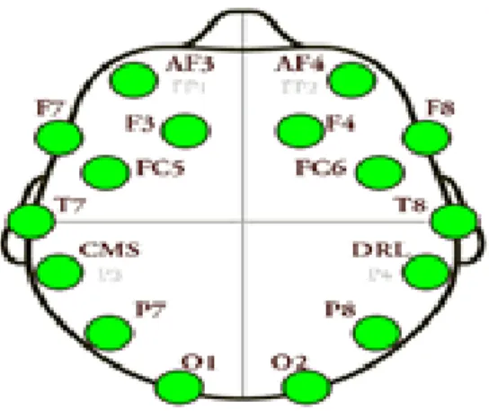
Emotiv EPOC is a 14 channels neuroheadset. It has CMS and DRL references. These are used to achieve optimal positioning for accurate spatial resolution. The channel names are: AF3, AF4, F3, F4, F7, F8, FC5, FC6, P3 (CMS), P4 (DRL), P7, P8, T7, T8, 01, 02 of these channels AF3, AF4, F3, F4, F7and F8 are used for taking frontal EEG data from the part of the brain which is involved in planning, organizing, problem solving, selective attention and personality [14]. FC5 and FC6 are used for taking EEG from the part of the brain which works on the processes that are engaged in preparing a response of front-central EEG [23], [24].
To take EEG from the region in the back of the brain which processes visual information and which is mainly responsible for visual processing O1 and O2 channels are used. In case for partial area which controls sensation FC5 and FC6 are used. There are two temporal lobes, one on each side of the brain located at about the level of the ears. These lobes allow a person to differentiate one smell from another and one sound from another. They also help in sorting new information. T7, T8 are used for taking data from temporal sites. Fig. 1.3 shows different connections of the sensors around the scalp and Table 1.1 is showing the Emotiv Headset configuration
.
Fig. 1.3 Sensors around the scalp Table 1.1
EMOTV HEADSET CONFIGURATION
Sl.no. Specification key Specifications 1 Number of channels 14 channels with
CMS/DRL references) 2 Sampling method Sequential sampling 3 Channel names AF3, AF4, F3, F4, F7, F8,
FC5, FC6, P3 (CMS), P4 (DRL), P7, P8, T7, T8, O1,
O2
4 Sampling rate ~128Hz but internally it is 2048Hz
5 Resolution 16 bits (14 bits effective) 1 LSB =0.51μV
6 Dynamic range 256mVpp
7 Bandwidth 0.2 - 45Hz and digital notch filters at 50Hz and
Sl.no. Specification key Specifications
8 Coupling mode AC coupled
9 Connectivity Proprietary wireless, 2.4GHz band 10 Impedance measurement Contact quality using
patented system
11 Battery Life 12 hours
12 Battery Type Li-Poly
Sequential sampling and Single Analog to digital converter (ADC) sequential sampling is used internally in the Emotiv device. Sequential sampling is a non-probability sampling technique where one has to take single or a group of data in a given time interval and analyze the results then again taking another group. of data if needed and so on [25], [26]. ADC is a device that converts a continuous voltage to a digital number as the quantity's amplitude. The conversion involves quantization of the input [27].
Fixed sampling rate of 128Hz is used. Internally it is oversampled at 2048 Hz per channel but this bandwidth is used to remove very high harmonic electric frequency. If this harmonics are not removed then it mixes with the brain waves. The signal is filtered to reduce the frequency to 128Hz for wireless transmission. The main reason other systems offer higher sampling rates is to allow enough bandwidth to remove these signals. EPOC has an upper bandwidth limit of around 43Hz to avoid 50Hz and 60Hz interference in order to avoid very first evoked potentials [28], [29], [30]. Dynamic range is 256Vpp for Emotiv EPOC and EPOC is built in digital 5th order Sinc filter. It is an "ideal" low-pass filter. Coupling mode of Emotiv EPOC is AC. Proprietary wireless networks is used for Emotiv headset as it makes one of its’ own protocols to get a reliable communication link in the 2.4 GHz band. The headset has a 3.7 volt and 600 milliamp rechargeable Lithium Battery inside it which provides users to use 12 hours continuously [31].
2.2 Emotiv Interfacing Software:
The Emotiv headset collects sequentially sampled data and supplies the data to an application called EPOC Control Panel. It processes the data and provides three built- in outputs and they are- Affective, Cognitive, Expressive suits [32]. Expressive suit detects facial movements and detects different states such as smile, raise brow, left wink, right wink etc. Affective suit measures positive mental states such as concentration, meditation and excitement. Cognitive part stores user’s neutral or relaxed mental state at first. Then system trained by the user’s specific thoughts. Control panel has a C++ API which allows other applications to communicate with the control panel software [33]. Our “PriSha” software connected with the control panel using this application.
Proper wearing of headset shows a visual image of sensors in the screen like figure 3. Green represents the best quality contact, while a led turns black that means there is no signal, red for very poor signal, orange for poor signal and yellow for fair signal. A graphical representation of incoming EEG signals is shown in the control panel which is used for training and recognition of thought. Emobot is a virtual robot in the control panel that copies different facial and head movements of user. It copies different expressive states such as left wink, right wink, raise brow, smile, and blink and clinch teeth. Actually EMG portion of EEG data records the electric activity that is produced from the muscle movements [5], [6]. When The EEG data is recorded then muscle movements provide some extra data and are counted as noise which is usually filtered. Brain wave frequencies have been categorized into bands of different frequencies and they are delta (0.1-3.5Hz), theta (4-7.5Hz), alpha (8-13Hz), and gamma (greater than 30Hz). Different activities of our brain create different frequencies. For example imaginary motor control which relates to our motor control creates alpha band frequency. The system understands different intention of the user through examining these frequencies [33], [34].
Electrooculography (EOG) is used to monitor the movements of eyes. The Emobot follows the user eyes if it is left or right [35], [3]. EMG and EOG are approximately same among different users so user does not need to train their data for getting facial output groups. These states can be used as
commands by setting different keywords, mouse control and even audio files can be triggered with different states. For example a facial expression such as “Clinch Teeth’ can be aligned with a “
audio files.
Cognitive part recognizes several directions of a floating virtual cube of control panel based on the several user thoughts. Thirteen intentional thoughts can be recognized and they are: UP, DOWN, RIGHT, LEFT, ROTATE RIGHT, ROTATE LEFT, LIFT, PUSH, PULL, DROP and INVISIBLE. The user need to train their data for each thought before using it. The user first has to provide neutral data by completely relaxing for eight second training period. Then for any specific thoughts out of the thirteen, the user has to train for eight seconds. The system stores the data using ERP which is taken during the training period and matches the data with the user thought to detect users’ specific thoughts. A user can set only four thoughts at a time with the keywords or mouse control and even audio files. In our application we used PUSH, DROP, RIGHT, LEFT for forward, backward, right and left operation.
2.3 Prototype Robot
Simple acrylic robot prototype is constructed which consists of two wheels that can move forward, backward, right and left, receiving command from the computer. The robot wheels are prepared by two 60RPM 12 volt DC motors. DC motor shield is also prepared to control the robot with the microcontroller. Figure4 is showing the robot that we prepared as a prototype for our system. Control software, control circuit, communication protocol and power are needed to control this piece of hardware.
2.4 Interfacing software “PriSha” with the control panel
A graphical user interface (GUI) named “BRAU PriSha Control Panel” is developed to receive signal from the EPOC control panel. Our GUI and backend software is built on C#. On GUI it has four buttons that can listen for keyboard input. The buttons are usually blue. With each consecutive press of the buttons W, A, D and Z the buttons becomes red which indicates which particular key has been pressed. Fig. 1.5 represents the software.
Fig. 1.5 “BRACU PriSha” Control Pannel
2.5 Sending output data from PriSha to the microcontroller
PriSha has a “connect” button on it as in Fig. 5. The software is designed in such a way that whenever the connect button is pressed the software directly connects with the microcontroller that is attached with an RF-433MHz transmitter. Before pressing the connect button the microcontroller has to be burned with particular code. Then while we press the connect button the microcontroller with transmitter part directly reads data from our software. Then the data is sent to another microcontroller. This microcontroller is attached with a motor shield. We built the motor shield for flexible operation of the microcontroller.
2.6 Motor Shield
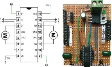
We have used a DC motor shield as it allows controlling the wheel of the robot smoothly. It also solves speed and heat regarding problems. We made this motor shield as in Fig. 1.6 using the following circuit diagram.
Fig. 1.6 Motor Shield
We used the above figure which represents the internal wiring of 88741 to build our motor shield .In our motor shield circuit we used 88741 microcontroller .Four input pins are I1, I2, I3, I4 and enable Pins are E1, E2. Outputs pins are O1, O2, O3, and O4 for two DC motors. Pin numbers 4,5,13 and 12 is grounded. Pin no. 8 requires 16 volt and pin no. 16 requires 5 volt voltage. Voltage sources are connected with the according pins with a simple circuitry connection. A maximum of 2 to 4 ampere current can be tolerated by the channels. To control the robot we programmed the microcontroller and we set the baud rate at 9600 and it is similar to the “PriSha” control panel software baud rate.
2.7 Robot moves from brain commands
Firstly, W, A, D and Z commands are set with the specific thoughts. For example, W can be set for Push command, A for Left, D for Right and Z for Drop command. Whenever the user thinks about pushing anything the control panel triggers W and the forward button in the “BRACU PriSha Control Panel” software is pressed. Then through transmitting over the transmitter part ultimately the receiver part at the robot end gets the signal and manipulates the signal to command the robot to go forward. Same thing happens for the other three outputs. We have used Expressive suite to command the robot to stop as Cognitive suit only lets the user to train four thoughts at a time. We have set the button X for "Smile" command. Whenever the user smiles X button is pressed and all the four buttons becomes white ultimately sending stop command to the microcontroller at the robot end.
CHAPTER III
EXPERIMENT AND RESULT ANALYSIS
We have experimented on ten users with different physical attributes to calculate the efficiency and the user friendliness of the Emotiv EPOC device. The challenging part was to train the disabled users for the experiment who later could smoothly control the robot. Each of the users had to provide their data regarding Age, Height, Weight, Physical Ability and Gender in the datasheet that had been provided to them before the experiment began. Then the author gave instructions to each of the users about training the neutral state and specific thoughts. The users were given to move the robot in four directions i.e. Forward, Backward, Left and Right. For moving the robot forward, Backward, Left and Right we used PUSH, DROP, LEFT and RIGHT thoughts respectively. Each user was given to move the robot in each direction for five times. For example a user had to think of pushing five times to move the robot forward for five times.
We calculated the efficiency of each thought commands for every user by calculating the successful thought output. For example if a user could successfully think (Pushing the cube inward) Push command for the all five times then he/she got 100% on that particular command. While trying to Push if the cube (which represents the specific thought output in the control panel) went in the other directions rather than the expected direction that that try was marked as zero. Thus in total two hundred and fifty data were taken from the entire users for Push, Left, Right and Drop commands. We have used Tally method to calculate efficiency of age range 14 to 20 and 21 to 30 in percentage. Then from the percentages of the four commands we have found the average output percentage. There was no significant variation based on weight, height and gender.
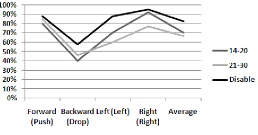
Fig. 1.7 Graphical analysis of the finding from the experiment
While experimenting, we noticed that the disabled user had more mental strength and their average success rate was 82% where for the age range 21-30 it was 70.5 and 67% was for the age range 14-20. Besides that, figure 7 shows that the users, age ranging from 21 to 30 years somehow had strong potential in Push command and the average rate is 85% and worst potential in Drop command and the average success rate is 46%. In every cases Right command was dominating over the Left command and it was most acute for the user aged 14 to 20 years. In every cases Right command was dominating over the Left command and it was most acute for the user aged 14 to 20 years. From figure 1.6 we see that normal users aging from 14-20 years had greater success rate in Left command compared to the users of
age 21-30 years and worst in Drop command. Right and Left command had nearly same rate. Push command was dominating. There was no notable difference on the output based on gender. Thought pattern had an important role. The Emotiv device may have some internal algorithm with some common thought patterns for every thought. It can catch a certain pattern of thoughts and works best when those particular thoughts have been imagined under that defined pattern.
CHAPTER IV
Extended Part: Brain Controlled Wheelchair
After measuring the cognitive efficiency of the device Emotiv EPOC in robot control the research was extended to observe its performance on a realistic project and that is how this research has found its way to build a brain controlled wheelchair. Along with this, the objective of this extended part was also to design a cheaper brain controlled wheelchair which is also efficient and at the same time simpler in design architecture .
4.1 Design of the wheelchair:
The wheelchair was designed from scratch and the main focus was to make it cheaper and simple at the same time. First of all a chassis of a normal wheelchair (non-electric) has been bought and it has been r re-designed through removing the wheels. Customized wheels have been built according to the plan and have been added with the wheelchair. After that the motors and the motor control circuit were added.
Fig: 1.8 The Wheelchair
4.2 The Motor:
The wheelchair motor model is EC Series (No.080737) and was bought from Motion Tech Motor.The motor comes with four wires. Two of the wires are with white clips and are used for automatic braking and the other two red and black wires are used as the motor leads. After applying voltage in the leads it is necessary to apply 24V across the white wires or else the motor does not get started. The motor also has a manual braking system. It has a lever which is turned to brak the motor instantly.The motor has the following specifications:
Table 1.2 Specifications of the motor
Fig1.9 The wheelchair motor
4.3 Motor Control Circuit:
Preparing the motor control circuit was the toughest part. The wheelchair motors comes with four output channels where two channels are used for automatic electrical braking mechanism. The other two channels are used as leads of the motor. To start the motor the channels which are used for automatic braking should be connected to 24V and other one should be connected to the ground. Thus the motor releases the brake mechanism and Serial No. Specification key Specifications
1 Torque 150W~400 W
2 No Load current (max) 2.67 Ampere
3 Voltage 24Volts (Peak)
4 Ratio 1:32
5 Speed 3800+/- 100 rpm
6 Noise 62 dBA(max)
7 Braking system Manual and
while the voltage is given across the two leads of the motor the motor runs. The motor approximately draws 3 ampere current without any load but with loads more than 100Kg the motor draws a significant amount of current which is nearly 10 ampere. We had to build a sophisticated motor driver in order to facilitate the motor to draw 20 amperes of current easily and at the same time change the directions of the motor with wider range of control. The motor driver was built on a simple technique which is known as H-bridge motor control. The concepts of a H-bridge circuit is pretty simple which is an electronic circuit that enables a voltage to be applied across a load in either direction. These circuits are often used in robotics and other applications to allow DC motors to run forwards and backwards [53]. The figure shows how an H-bridge circuit works .
Fig1.10 H-Bridge Circuit
In the Fig. 1.9, when switch S1 and switch S4 are closed at the same time switch S2 and switch S3 must be open. Thus current will flow from switch S1 through switch S4turning the motor runs clockwise. Accordingly when switch S2 and switch S3 are closed then switch S1 and S4 must be open thus allowing the current to flow in the opposite direction. The motor runs anticlockwise.
The circuit in this project has also used this technique of controlling the motor. Mosfet and Transistor based H-bridge circuit were found not to be so effective for dealing with high current so we had to implement the H-bridge circuit using relays. At the beginning, four SPDT relays were used to build the control mechanism. The circuit is same. Four relays were used in case of the switches in the above circuit. The relays were triggered to On state by using
transistor across its common pin and the direction is reversed using another transistor across the coil. Later, to make the circuit even simpler a DPDT relay was used to implement the H-bridge circuit. Fig. 1.10 shows how the circuit was implemented using H-Bridge techniques. Fig 1.11 shows the complete H bridge circuit, designed on PCB.
Fig1.11 Schemetic of the circuit
The circuit takes input from a microcontroller. When PIN4 is Logic “High” then the motor turns on and moves in the forward direction. When PIN5 is logic “High” then the polarity of the current becomes opposite as in the H-bridge circuit and current flows from the coil though relay pins 4 and 8 and thus the motor moves in the opposite direction. The motor turns off when PIN4 is logic “Low” . The relay turns off when PIN5 is logic “LOW”.
4.4 Brain to wheelchair:
The brain signal is encoded and decode by the EEG extractor device Emotiv EPOC and it has a control panel where there is a cube which moves in different directions to visualize which direction the user is thinking about. Once the user thinks about moving the cube in any particular direction then the extracted EEG data is matched against the previously stored data of particular thought patterns for that particular user. Then after matching the data a decision is made about which direction the user is thinking about. As described, Emotiv provides a free control panel software which provides with a facility of triggering key values from the thoughts. It has a common API system and so programs with many standard programming languages may take input from the panel. We made a program using Visual Studio in C# programming language. The program listens for some particular key triggers from EPOC control panel. Once the key is pressed the software shows a key press in the screen and at the same time it sends the data to a microcontroller which is programmed to make the motor move in the particular directions by sending data at different pins of the motor driver based on the values sent to it from the VS software. The whole procedure is shown below:
CHAPTER V
Extended Part: Result and Discussion
The wheelchair moved efficiently based on the different commands. Rather than just directing the motor to move in a particular direction the motor was was directed to move in any particular direction for a certain amount of time only. For example, if a user thinks to push the cube in the EPOC control panel in the forward direction which triggers the “w” key and ultimately the “Prisha” software ditects and presses the visual key, defined for Forward direction. The software automatically sends the data to the microcontroller and the microcontroller sends logic High to the Motor input pin of the driver.The ddriver makes the motor to spin in the clock wise direction.As delay is introduced for each command in the microcontroller,the wheelchair goes in any directon for a certain amount of time.This largely helps to avoid any sudden accidents. The wheelchair was tested on a certain amount of user and 87% of them thinks it has an efficient and reliable control system. While 3% thinks that it was a hassle and 10% user reported that the wheelchair makes a little delay between the transistion from one state to another. This point has been investigated and has been found that the transistion delay is caused by the switching delay of the relay.
CHAPTER VI
Conclusion
Emotiv EPOC is a user friendly device. Even a novice user can use it after training for two to five times. This device has shortcomings too. The experimented users have commented as follows: 5% user felt that the device works well when they move their hands. 2% felt that the device works better just after a command has been trained. 4% felt that the device cannot work simultaneously. They reported that they think in one particular direction and the cube moves in other directions. 75% user felt that it works better when they imagined any command rather than thinking about the cube to push inside. For example, when they thought about pushing a big thing the command worked correctly and frequently. Rest 14% was seemed using both imagination and hand movements. They could not reach to any conclusion. Summarizing the user feelings we get that experience with the Emotiv device vary user to user. Through experimenting various time it has been found that the device has no advantages over hand movements. Rather hand movement effects the EEG data signal acquisition. During the eight second training period the user has to repeatedly imagine about specific thoughts to get better response. Some user directly tries to move the cube through visualizing and thinking to move it to a particular direction. This also works good but best recommended for the noisy environment. User with long hair had to face hardship to use this device. They had to wet their head to acquire the sensor contact quality. Though Emotiv has remarkable shortcomings still this cheap consumer headset has opened up a new era for the disabled person to get their ability back by dint of an acceptable cost. The Cognitive suit efficiency may be a lagging factor but the combination of Expressive suit along with Cognitive suit makes the device not only reliable but also worthy of controlling robots, prosthetic hands, wheelchair etc. smoothly. Brain Computer Interface in robotics has been a challenge for last few years and efficiency is the main factor here. This paper observed the cognitive efficiency in robot control. In the later part the paper described a simple and cheap way to build a BCI
based wheelchair. The design is unique because of its efficient control system, simple architecture and the designed wheels. Though the relay has certain level of delay in switching from one direction to other but it did not occur as a significant problem as to change from one thought to another there is also a delay. Both delays approximately nullify each other to provide an efficient control system.
Appendices
A. EEG:
The Electroencephalography (EEG) is the recording of electrical activity along the scalp. EEG measures voltage fluctuations resulting from ionic current flows within the neurons of the brain [37]. In clinical contexts, EEG refers to the recording of the brain's spontaneous electrical activity over a short period of time, usually 20–40 minutes, as recorded from multiple electrodes placed on the scalp. Diagnostic applications generally focus on the spectral content of EEG, that is, the type of neural oscillations that can be observed in EEG signals [37].
EEG is most often used to diagnose epilepsy, which causes obvious abnormalities in EEG readings [38]. It is also used to diagnose sleep disorders, coma, encephalopathies, and brain death. EEG used to be a first-line method of diagnosis for tumors, stroke and other focal brain disorders,[39] but this use has decreased with the advent of high-resolution anatomical imaging techniques such as MRI and CT. Despite limited spatial resolution, EEG continues to be a valuable tool for research and diagnosis, especially when millisecond-range temporal resolution (not possible with CT or MRI) is required [38].
Derivatives of the EEG technique include evoked potentials (EP), which involves averaging the EEG activity time-locked to the presentation of a stimulus of some sort (visual, somatosensory, or auditory) [39]. Event-related potentials (ERPs) refer to averaged EEG responses that are time-locked to more complex processing of stimuli; this technique is used in cognitive science, cognitive psychology, and psychophysiological research [38].
B. EOG:
Electrooculography (EOG/E.O.G.) is a technique for measuring the corneo-retinal standing potential that exists between the front and the back of the human eye. The resulting signal is called the electrooculogram. Primary applications are in ophthalmological diagnosis and in recording eye movements. Unlike the electroretinogram, the EOG does not measure response to individual visual stimuli [40].
To measure eye movement, pairs of electrodes are typically placed either above and below the eye or to the left and right of the eye [42]. If the eye moves from center position toward one of the two electrodes, this electrode "sees" the positive side of the retina and the opposite electrode "sees" the negative side of the retina [41]. Consequently, a potential difference occurs between the electrodes. Assuming that the resting potential is constant, the recorded potential is a measure of the eye's position [41].
C. EMG:
Electromyography (EMG) is a technique for evaluating and recording the electrical activity produced by skeletal muscles.[43] EMG is performed using an instrument called an electromyograph, to produce a record called an electromyogram. An electromyograph detects the electrical potential generated by muscle cells[44] when these cells are electrically or neurologically activated. The signals can be analyzed to detect medical abnormalities, activation level, or recruitment order or to analyze the biomechanics of human or animal movement [45].
D. Evoked Potential:
An evoked potential or evoked response is an electrical potential recorded from the nervous system of a human or other animal following presentation of a stimulus, as distinct from spontaneous potentials as detected by electroencephalography (EEG), electromyography (EMG), or other electrophysiological recording method [47].
Evoked potential amplitudes tend to be low, ranging from less than a microvolt to several microvolts, compared to tens of microvolts for EEG,
millivolts for EMG, and often close to a volt for ECG. To resolve these low-amplitude potentials against the background of ongoing EEG, ECG, EMG, and other biological signals and ambient noise, signal averaging is usually required [46]. The signal is time-locked to the stimulus and most of the noise occurs randomly, allowing the noise to be averaged out with averaging of repeated responses.[46]
Signals can be recorded from cerebral cortex, brain stem, spinal cord and peripheral nerves [48]. Usually the term "evoked potential" is reserved for responses involving either recording from, or stimulation of, central nervous system structures [47]. Thus evoked compound motor action potentials (CMAP) or sensory nerve action potentials (SNAP) as used in nerve conduction studies (NCS) are generally not thought of as evoked potentials, though they do meet the above definition [48].
E. Programming code of Microcontroller :
The whole code has been burned into an arduino board.
E.a Arduino:
Arduino is a family of single-board microcontrollers, intended to make it easy to build interactive objects or environments [49]. The hardware consists of an open-source hardware board designed based on an 8-bit Atmel AVR microcontroller or a 32-bit Atmel ARM. The systems provide sets of digital and analog I/O pins that can be interfaced to various extension boards and other circuits. Some models feature a USB interface for loading code from personal computers [50].
The first Arduino was introduced in 2005. Its designers sought to provide an inexpensive and easy way for hobbyists, students, and professionals to create devices that interact with their environment using sensors and actuators [51]. Common examples for beginner hobbyists include simple robots, thermostats and motion detectors. Arduino boards come with a simple integrated development environment (IDE) that runs on regular personal computers and allows users to write programs for Arduino using C or C++ [52].
Arduino boards can be purchased assembled or as do-it-yourself kits. Hardware design information is available for those who would like to assemble an Arduino by hand [52].
E.b Arduino IDE code:
E.c Transmitter code:
#include <VirtualWire.h> void setup() { Serial.begin(9600); Serial.println("setup");
vw_setup(2000); // Bits per sec
vw_set_tx_pin(3); //Transmitter Data Pin to Digital Pin 3 }//close setup void loop() { if (Serial.available() > 0) {
int sendByte = Serial.read();//Starts reading data from the serial monitor once condition is met
switch (sendByte){
case 'w': //if the controller type w {
char *msg2 = "w";
digitalWrite(13, true); // Flash a light to show transmitting
vw_send((uint8_t *)msg2, strlen(msg2));//send byte to the receiver vw_wait_tx(); // Wait until the whole message is gone
digitalWrite(13, false); break;
}
case 'z': //if controller types z {
char *msg2 = "z";
digitalWrite(13, true); // Flash a light to show transmitting
vw_send((uint8_t *)msg2, strlen(msg2));//send byte to the receiver vw_wait_tx(); // Wait until the whole message is gone
digitalWrite(13, false); break;
}
case 'a': //if controller types a {
char *msg2 = "a";
digitalWrite(13, true); // Flash a light to show transmitting
vw_send((uint8_t *)msg2, strlen(msg2));//send byte to the receiver vw_wait_tx(); // Wait until the whole message is gone
digitalWrite(13, false); break;
}
case 'd': //if controller types d {
char *msg2 = "d";
digitalWrite(13, true); // Flash a light to show transmitting
vw_send((uint8_t *)msg2, strlen(msg2));//send byte to the receiver vw_wait_tx(); // Wait until the whole message is gone
digitalWrite(13, false); break;
}
case 'x': //if controller types x {
char *msg2 = "x";
vw_send((uint8_t *)msg2, strlen(msg2));//send byte to the receiver vw_wait_tx(); // Wait until the whole message is gone
digitalWrite(13, false); break;
}
default://if any other value is entered {
Serial.println("PriSha wrong entry");//print wrong entry in the serial monitor } }// close switch-case }//close if }//close loop // End Of Code
E. d Reciever code:
#include <AFMotor.h> #include <VirtualWire.h>
AF_DCMotor motor1(3); // create motor #2, 64KHz pwm AF_DCMotor motor2(4);
void setup() {
Serial.begin(9600); // Debugging only Serial.println("setup");
motor1.setSpeed(255); motor2.setSpeed(255); // Initialise the IO and ISR }//close setup
void loop() {
uint8_t buf[VW_MAX_MESSAGE_LEN]; uint8_t buflen = VW_MAX_MESSAGE_LEN; if (vw_get_message(buf, &buflen)) // Non-blocking { vw_setup(2000); // Bits per sec
vw_set_rx_pin(A1);//Receiver at Analog pin A1 vw_rx_start();// Start the receiver PLL running int i;
digitalWrite(13, true); // Flash a light to show received good message for (i = 0; i < buflen; i++)
{
Serial.print(buf[i]); if(buf[i] == 'w') {
motor1.run(FORWARD);//go forward when w is pressed motor2.run(FORWARD);
}
if(buf[i] == 'z') {
motor1.run(BACKWARD);//go backward when z is pressed motor2.run(BACKWARD);
}
if(buf[i] == 'a') {
motor1.run(FORWARD);//go left when a is pressed motor2.run(BACKWARD); } if(buf[i] == 'd') {
motor1.run(BACKWARD);//go right when d is pressed motor2.run(FORWARD);
}
if(buf[i] == 'x') {
motor1.run(RELEASE);// stop when x is pressed motor2.run(RELEASE); } } } }
E. e Wheelchair control code:
#define MOTOR1 4 #define DIR1 5 #define MOTOR2 6 #define DIR2 7 void setup() {
Serial.begin(9600); // Debugging only Serial.println("setup");
pinMode (4, OUTPUT); pinMode(5, OUTPUT); pinMode(6, OUTPUT); pinMode(7, OUTPUT); // Initialise the IO and ISR
// vw_setup(2000); // Bits per sec
// vw_set_tx_pin(3); //Transmitter Data Pin to Digital Pin 3 }//close setup void loop() { if (Serial.available() > 0) {
int inByte = Serial.read();//Starts reading data from the serial monitor once condition is met if (inByte == 119){ Serial.println("Forward"); digitalWrite(MOTOR1,HIGH); //motor on delay(1000);
digitalWrite(MOTOR1,LOW); //motor off delay(100); //wait for spikes to dissipate digitalWrite(MOTOR2,HIGH); //motor on delay(1000);
digitalWrite(MOTOR2,LOW); //motor off delay(100); //wait for spikes to dissipate
}
if (inByte== 122) {
Serial.println("Backward");
digitalWrite(DIR1,HIGH); //reverse direction delay(10000);
digitalWrite(MOTOR1,LOW); //motor off delay(100); //wait for spikes to dissipate digitalWrite(DIR2,HIGH); //reverse direction delay(10000);
digitalWrite(MOTOR2,LOW); //motor off delay(100); //wait for spikes to dissipate } if (inByte== 97) { Serial.println("Left");
digitalWrite(MOTOR1,HIGH); //forward direction delay(10000);
digitalWrite(MOTOR1,LOW); //motor off delay(100); //wait for spikes to dissipate digitalWrite(DIR2,HIGH); //reverse direction delay(10000);
delay(100); //wait for spikes to dissipate } if (inByte== 100) { Serial.println("Right");
digitalWrite(DIR1,HIGH); //reverse direction delay(10000);
digitalWrite(MOTOR1,LOW); //motor off delay(100); //wait for spikes to dissipate
digitalWrite(MOTOR2,HIGH); //forward direction delay(10000);
digitalWrite(MOTOR2,LOW); //motor off delay(100); //wait for spikes to dissipate
}
if (inByte== 120) {
Serial.println("stop");
digitalWrite(MOTOR1,LOW); //motor off digitalWrite(MOTOR2,LOW); //motor off }
{
Serial.println("Wheelchair wrong entry");//print wrong entry in the serial monitor } } } // End Of Code
F Code for “PriSha” software”: F. a SeialComm.cs using System; using System.Collections.Generic; using System.Linq; using System.Text; using System.IO.Ports; namespace EmoControl2 {
public class SerialComm {
public SerialPort serialPort; public String[] portNames; string selectedPort;
public SerialComm() {
serialPort = new SerialPort();
portNames = SerialPort.GetPortNames(); }
public bool connect(String portName) { try { if (!serialPort.IsOpen) { serialPort.PortName = portName; serialPort.Open(); selectedPort = portName; return true; } else { return false; } } catch (Exception) { disconnnect(); return false; } } void reconnect()
{
connect(selectedPort); }
public string send(String command) { try { if (serialPort.IsOpen) { serialPort.Write(command); return "Sending: " + command; } } catch (Exception) { disconnnect(); reconnect(); }
return "Not Sending"; }
public string read() {
return serialPort.ReadLine(); }
public void disconnnect() { if (serialPort.IsOpen) { serialPort.Close(); serialPort.Dispose(); } } } } F. b MainWindow.xaml.cs using System; using System.Collections.Generic; using System.Linq;
using System.Text; using System.Windows; using System.Windows.Controls; using System.Windows.Data; using System.Windows.Documents; using System.Windows.Input; using System.Windows.Media; using System.Windows.Media.Imaging; using System.Windows.Navigation; using System.Windows.Shapes; namespace EmoControl2 { /// <summary>
/// Interaction logic for MainWindow.xaml /// </summary>
public partial class MainWindow : Window {
SerialComm serialComm; public MainWindow() {
InitializeComponent();
serialComm = new SerialComm(); }
private void Window_KeyDown(object sender, KeyEventArgs e) {
labelOutput.Content = "" + e.Key; if (e.Key == Key.W)
{
rectangleUp.Fill = new SolidColorBrush(Colors.Brown);
rectangleRotate.Fill = new SolidColorBrush(Colors.CornflowerBlue); rectangle1.Fill = new SolidColorBrush(Colors.CornflowerBlue); rectangle2.Fill = new SolidColorBrush(Colors.CornflowerBlue);
serialComm.send("w");
}
else if (e.Key == Key.D) {
rectangleUp.Fill = new SolidColorBrush(Colors.CornflowerBlue); rectangleRotate.Fill = new SolidColorBrush(Colors.Brown); rectangle1.Fill = new SolidColorBrush(Colors.CornflowerBlue); rectangle2.Fill = new SolidColorBrush(Colors.CornflowerBlue);
serialComm.send("d"); }
else if (e.Key == Key.A) {
rectangleUp.Fill = new SolidColorBrush(Colors.CornflowerBlue); rectangleRotate.Fill = new SolidColorBrush(Colors.CornflowerBlue); rectangle1.Fill = new SolidColorBrush(Colors.Brown);
rectangle2.Fill = new SolidColorBrush(Colors.CornflowerBlue); serialComm.send("a");
}
else if (e.Key == Key.Z) {
rectangleUp.Fill = new SolidColorBrush(Colors.CornflowerBlue); rectangleRotate.Fill = new SolidColorBrush(Colors.CornflowerBlue); rectangle1.Fill = new SolidColorBrush(Colors.CornflowerBlue); rectangle2.Fill = new SolidColorBrush(Colors.Brown);
serialComm.send("z"); }
else {
rectangleUp.Fill = new SolidColorBrush(Colors.Silver); rectangleRotate.Fill = new SolidColorBrush(Colors.Silver); rectangle1.Fill = new SolidColorBrush(Colors.Silver); rectangle2.Fill = new SolidColorBrush(Colors.Silver); serialComm.send("x");
} }
private void button1_Click(object sender, RoutedEventArgs e) {
serialComm.connect("COM6"); }
private void Grid_KeyDown(object sender, KeyEventArgs e) {
private void BRACUPrIsHA_KeyDown(object sender, KeyEventArgs e) { } } } F. c MainWindow.xaml <Window x:Class="EmoControl2.MainWindow" xmlns="http://schemas.microsoft.com/winfx/2006/xaml/presentation" xmlns:x="http://schemas.microsoft.com/winfx/2006/xaml"
Title="MainWindow" Height="350" Width="531"
KeyDown="Window_KeyDown" FontFamily="Bodoni MT"> <Grid KeyDown="Grid_KeyDown" Height="287">
<Grid.ColumnDefinitions>
<ColumnDefinition Width="284*" /> <ColumnDefinition Width="220*" /> <ColumnDefinition Width="5*" /> </Grid.ColumnDefinitions>
<Label Content="Label" Height="28" HorizontalAlignment="Left"
Margin="170,105,0,0" Name="labelOutput" VerticalAlignment="Top" /> <Rectangle Fill="{StaticResource {x:Static
SystemColors.GradientActiveCaptionBrushKey}}" Height="50"
HorizontalAlignment="Left" Margin="229,171,0,0" Name="rectangleRotate" Stroke="Black" VerticalAlignment="Top" Width="64" Grid.ColumnSpan="2" /> <Rectangle Height="49" HorizontalAlignment="Left" Margin="182,238,0,0" Name="rectangle2" Stroke="Black" VerticalAlignment="Top" Width="75" Fill="{StaticResource {x:Static
SystemColors.GradientActiveCaptionBrushKey}}" />
<Border BorderBrush="Silver" BorderThickness="1" Height="100" HorizontalAlignment="Left" Margin="0,-23,0,0" Name="BRACUPrIsHA"
VerticalAlignment="Top" Width="604" DataContext="{StaticResource {x:Static SystemColors.ActiveCaptionBrushKey}}" Background="#FFBBFCFC"
<TextBlock Height="43" Name="textBlock1" Text="BRACU Illuminatus" FontFamily="Baskerville Old Face" Width="311"
TextTrimming="CharacterEllipsis" TextWrapping="Wrap" FontWeight="Normal" FontStyle="Normal" FontSize="26" Foreground="#FF0D0A6F"
Focusable="True"><TextBlock.Background><ImageBrush /></TextBlock.Background></TextBlock>
</Border>
<Border BorderBrush="Silver" BorderThickness="1" Height="92" HorizontalAlignment="Left" Name="border1" VerticalAlignment="Top" Width="139" Margin="0,-14,0,0">
<Border.Background>
<ImageBrush ImageSource="/EmoControl2;component/Images/url.jpg" /> </Border.Background>
</Border>
<Border BorderBrush="Silver" BorderThickness="1" Height="172" HorizontalAlignment="Left" Margin="14,82,0,0" Name="border2" VerticalAlignment="Top" Width="211" Grid.Column="1"
Grid.ColumnSpan="2"> <Border.Background> <ImageBrush ImageSource="/EmoControl2;component/Images/emotiv-headset.jpg" /> </Border.Background> </Border>
<Border BorderBrush="Silver" BorderThickness="1" Height="90" HorizontalAlignment="Left" Margin="94,-14,0,0" Name="border3" VerticalAlignment="Top" Width="138" Grid.Column="1"
Grid.ColumnSpan="2"> <Border.Background> <ImageBrush ImageSource="/EmoControl2;component/Images/FPJI3R5FNNK1C0S.LARG E.jpg" /> </Border.Background>
</Border>
<Border BorderBrush="Silver" BorderThickness="1" Height="205" HorizontalAlignment="Left" Margin="-22,82,0,0" Name="border4" VerticalAlignment="Top" Width="161" Visibility="Visible"
OpacityMask="{StaticResource {x:Static SystemColors.ActiveCaptionTextBrushKey}}"> <Border.Background> <ImageBrush ImageSource="/EmoControl2;component/Images/simpletestiq01.jpg" /> </Border.Background> </Border>
<Rectangle Name="rectangle1" Stroke="Black" Fill="{StaticResource {x:Static SystemColors.GradientActiveCaptionBrushKey}}" Margin="149,171,75,66" /> <Rectangle Name="rectangleUp" Stroke="Black" Fill="{StaticResource
{x:Static SystemColors.GradientActiveCaptionBrushKey}}" Margin="182,105,27,135" />
<Button Content="Connect" Grid.Column="1" Height="30"
HorizontalAlignment="Left" Margin="33,257,0,0" Name="button1" VerticalAlignment="Top" Width="157" Click="button1_Click" /> </Grid>
LIST OF REFERENCES
[1] P.L. Nunez, R. Srinivasa, “Electric fields of the brain: The neurophysics of EEG,” Oxford University Press, 1981.
[2] O.D. Creutzfeldt, S. Watanabe, H.F. Lux, “Relations between EEG
phenomena and potentials of single cortical cells. I. Evoked responses after thalamic and epicortical stimulation,” Electroencephalography and Clinical Neurophysiology, Vol. 20, No. 1, Pages 1–18, January 1966.
[3] R. Barea, L. Boquete, M. Mazo, E.J. López, “Wheelchair guidance strategies using EOG,” Intell. Robot. Syst., vol.34, Issue 3, pp 279-299, 2002.
[4] O. Bai, V. Rathi, P. Lin, D. Huang, H. Battapady, D.Y. Fei, L. Schneider, E. Houdayer, X. Chen, M.C. Hallett, “Prediction of human voluntary movement before it occurs,” Clinical Neurophysiology Volume 122, Issue 2, Pages 364–
372, February 2011.
[5] T. Yagi, Y. Kuno, Y. Uchikawa, “Prediction of eye movements from EEG,”
Proceedings of the 6th International Conference on Neural Information Processing (ICONIP’99), Perth Austria, 16-20, pp. 1127-1131, Nov 1999. [6] V. Morash, O. Bai, S. Furlani, P. Lin, M. Clin Hallett, “Classifying EEG
signals preceding right hand, left hand, tongue, and right foot movements and motor imageries,” Neurophysiol., pp. 2570–2578, Nov 2008.
[7] C. Lin, L.W. Ko, J.C. Chiou, J.R. Duann, R.S. Huang, S.F. Liang, T.W. Chiu, T.P. Jung, “Noninvasive neural prostheses using mobile and wireless EEG,” published in the proceedings of the IEEE, vol.:96, issue: 7, pages
[8] C. Zhao, C. Zheng, M. Zhao, Y. Tu, J. Liu, “Multivariate autoregressive
models and kernel learning algorithms for classifying driving mental fatigue based on electroencephalographic,” Expert Systems with Applications,
Vol.:38, issue 3, Mar 2011.
[9] B.T. Jap, S. Lal, P. Fischer, E. Bekiaris, “Using EEG spectral components to assess algorithms for detecting fatigue,” Expert System Applications, vol.
36, Issue 2, Part 1, pages 2352-2359, Mar2009.
[10] A.F. Neto, W.C. Celeste, V.R. Martins, T.F.B. Filho, M.S. Filho, “Human-Machine interface based on electro-biological signals for mobile vehicles,” In
Proceedings of the IEEE International Symposium on Industrial Electronics (ISIE’06), Montreal, QC, Canada, pp. 2954-2959, 9–13 July 2006.
[11] H. De Rosario, J.S. Solaz, X. Rodri, N. Guez, L.M. Bergasa, “Controlled
inducement and measurement of drowsiness in a driving simulator,” Intelligent transport System, vol. 4, issue 4, pages 280-288, ISSn: 1751-956, December 2010.
[12] H.J. Eoh, M.K. Chung, S.H. Kim, “Electroencephalographic study of drowsiness in simulated driving with sleep deprivation”, Int. J. Ind. Ergon,
2005.
[13] Durgesh Nandan Jha, “Patient's wish is robot's command” TNN, 06.11
AM IST, Mar 19, 2011.
[14] Daly JJ1, Wolpaw JR, “Brain-computer interfaces in neurological rehabilitation,” The Lancet Neurology, Volume 7, Issue 11, Pages 1032–1043,
[15] C.T. Lin, L.W. Ko, I.F. Chung, T.Y. Huang, Y.C. Chen, T.P. Jung, S.F. Liang, “Adaptive EEG-based alertness estimation system by using ICA-Based fuzzy neural networks”, IEEE Xplore, vol.53, Isuue:11, Nov-2006.
[16] K.V. Shenoy, G. Santhanam, S.I. Ryu, A. Afshar, B.M. Yu, V. Gilja, M.D. Linderman, R.S. Kalmar, J.P. Cunningham, C.T. Kemere, A.P. Batista, M.M. Churchland, T.H. Meng, “Increasing the performance of cortically-controlled prostheses,” Conf Proc IEEE Eng Med Biol Soc. Suppl: 6652-6, 2006
[17] B. Abou-Khalil, “Atlas of EEG & Seizure Semiology,” Musilus, K.E.,
Elsevier, 2006
[18] J. Polich, “Updating P300: An integrative theory of P3a and P3b,” Clinical
Neurophysiology, Volume 118, Issue 10, Pages 2128-2148, October 2007. [19] E. M. Karl, F. Toufic, “Spehlmann's Evoked Potential Primer,”
Butterworth-heinemann, ISBN 7506-7333-8, 2001
[20] K.R.I. Shna, V. Shenoy, “Human cortical prostheses: lost in translation?,”
Stephen I. Ryu, M.D and Neurosurg Focus, Vol. 27, No.1, Jul 2009
[21] Kubler, Kotchoubey, Kaiser, Wolpaw, and Birbaumer, “Brain- Computer Communication: Unloacking the locked in,” Psychol Bull, Vo. 127, No. 3, pp.
358-75, May 2001. [22] http://emotiv.com/developer/SDK/UserManual.pdf [visited on 18/01/14] [23] http://www.ncbi.nlm.nih.gov/pubmed/12661970 [visited on 18/01/14]. [24] http://www.waiting.com/brainanatomy.html [visited on 25/01/14]. [25] http://betterevaluation.org/evaluation-options/sequential [visited on 20/01/14]. [26] http://explorable.com/sequential-sampling [visited on 20/01/14].
[27] http://en.wikipedia.org/wiki/Analog-to-digital_converter [visited on 18/01/14]. [28]http://emotiv.com/forum/messages/forum12/topic1926/message11109 [visited on 18/01/14]. [29] http://emotiv.com/forum/messages/forum15/topic1697/message9864 [visited on 18/01/14] . [30] http://emotiv.com/ideas/forum/forum15/topic3189/[ visited on 18/01/14] [31] http://emotiv.wikia.com/wiki/Emotiv_EPOC [visited on 18/01/14]. [32] http://www.emotiv.com/EPOC/features.php visited on [18/01/14]. [33]http://www.cosc.canterbury.ac.nz/research/reports/HonsReps/2012/hons_ 1201.pdf[ visited on 10/02/14]. [34] http://neurogadget.com/2014/01/30/think-drive-brain-driven-hybrid-vehicle-project-india/9701 [ visited on 16/02/2014]. [35] http://en.wikipedia.org/wiki/Electrooculography) 2010/09/13/ [visited on 18/01/14].
[36] Microcontroller projects using the Basic Stamp (2nd ed.). Focal Press. p. 344. ISBN 978-1-57820-101-3; Al Williams.
[37] Karl E. Misulis, Toufic Fakhoury (2001). Spehlmann's Evoked Potential Primer. Butterworth-heinemann. ISBN 0-7506-7333-8.
[38] O’Shea, R. P., Roeber, U., & Bach, M. (2010). Evoked potentials:
Vision. In E. B. Goldstein (Ed.), Encyclopedia of Perception (Vol. 1, pp. 399-400, xli). Los Angeles: Sage. ISBN 978-1-4129-4081-8