I
NTRODUCTION
The quality of life and modern economy depends more and more on the availability of ubiquitous low-cost broadband access. The demand on end-user data rates keeps increasing, which fuels the development and deployment of new systems. An analysis of this evolutionary process reveals that there is a gap — a missing, not foreseen sys-tem generation — to which we devote this arti-cle. The study presented in the following suggests labeling the missing generation as Generation 4.
Our classification of broadband systems into generations includes only broadband systems operating on the twisted-copper pairs of the public telephony network and optical fiber, namely, digital subscriber line (DSL) systems and fiber access systems. The future, as the pre-sent, certainly also will see other technologies such as coaxial-cable access systems (using cable-TV infrastructure) or fixed wireless access sys-tems, but these are beyond the scope of this presentation.
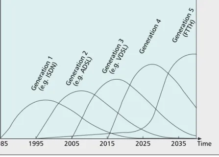
In Fig. 1, the principle deployment history for broadband access equipment is illustrated. Note that the classification of systems as generations in Fig. 1 is introduced to define and emphasize a gap in the foreseen broadband evolution and is not a generally accepted terminology. The term broadband access equipment, for example, loose-ly denotes communications equipment that is
intended for Internet access with a permanent connection, that is, post dial-up systems. During the last two decades, two generations of broad-band access systems for telephone loops were deployed: Generation 1, which is mainly based on integrated services digital network (ISDN) [1], and Generation 2, which is mainly based on asymmetric DSL (ADSL) [2]. Both generations are characterized by systems deployed from the central office. Generation 1 marked the start of data communication beyond dial-up modems, whereas Generation 2 added a “real” transport network and user bandwidths that are comfort-ably greater than voiceband modems.
Today, we are seeing the launch of the third-generation broadband access system — the very-high-bit-rate DSL (VDSL) family [2] — that will provide customer data rates of up to 100 Mb/s. Whereas ADSL operates from the central office, often over cables that are several kilometers long, VDSL is designed to operate over shorter loops. Therefore, the VDSL equipment is nor-mally placed in cabinets, resulting in a typical loop length that is below one kilometer. The backhaul solution, namely, the technology to bring data between the transport network and the cabinet, is almost exclusively based on opti-cal fiber technology today. The transition from the second generation to the third generation thus implies an extension of the fiber network from the central offices to the cabinets. This is a first and fundamental step toward building a large-scale fiber-to-the-home (FTTH) infra-structure.
The fourth generation, presented and dis-cussed here, is nothing more than the logical extension of the thinking behind Generation 3. The communication requirements of the future are assumed to require data rates an order of magnitude higher than Generation 3, that is, a step from around 100 Mb/s to around 1 Gb/s. To deliver these data rates using the in-place copper architecture requires even shorter loops. The key question is whether or not there exists a natural place to deploy the new transmission equipment in an economical fashion.
With the fourth generation broadband
con-A
BSTRACT
Fixed-broadband access technology is evolving from exclusively copper-based solutions to hybrid fiber-copper architectures. This article presents the expected next step in the evolution of broad-band systems, which we call the fourth-generation broadband concept. It identifies a technical, infras-tructural, and economical niche and describes how the fiber-access network is extended and forked to feed a last and ultimate generation of DSL sys-tems, shown to have gigabit potential. The under-lying infrastructural concept is presented, economic aspects are described and discussed, and achievable data rates are calculated.
A
DVANCES IN
S
IGNAL
P
ROCESSING FOR
C
OMMUNICATIONS
Per Ödling, Thomas Magesacher, Stefan Höst, and Per Ola Börjesson, Lund University
Miguel Berg, Ericsson AB
Enrique Areizaga, Tecnalia-robotiker
The Fourth Generation
Broadband Concept
ODLING LAYOUT 12/18/08 3:25 PM Page 63
1It was recently pointed out by British Telecom researchers that technolo-gy developments soon will make it feasible to exploit the “last” DP to deliver broadband services, spawning the work pre-sented here.
cept (4GBB), we present the “last” distribution point (DP) as a candidate from which broad-band services could be delivered in a technically and economically feasible fashion. The copper plant is a star network, forking out into finer and finer segments (fewer and fewer lines running together) until eventually individual twisted pairs reach their respective user premises. The last DP can be found by following the lines from the users’ homes and backwards into the network, where normally after 20 to 200 m you find a point in which a number of lines merge together and form a bundle. This is the most outward point at which a modem pack can be installed serving a number of customers, for example, 10 to 30. The last DP was considered as early as 1990, in the form of fiber-to-the building (FTTB) and fiber-to-the-curb (FTTC) discussions, but at the time it was not associated with a correspond-ing new generation of copper-access (DSL) equipment making full use of the greater band-width offered by the shorter loops. The earlier FTTB and FTTC discussions left few marks in the standardization processes and were essential-ly abandoned.1We believe that it may be time to
develop the idea of moving to the last DP, but now dressed in modern technology and based on twenty years of experience from the develop-ment of the broadband market.
A natural question is, of course, how much this infrastructural quantum leap will cost, espe-cially in comparison with installing optical fibers all the way out to the customer, that is, fiber-to-the home (FTTH). We return to this in fiber-to-the next section.
Figure 1 contains historical data for Genera-tions 1 to 3 and predicGenera-tions of the deployment timescale for the fourth and the fifth generation broadband. So far, the transition between any con-secutive pair of earlier generations has taken about ten years. This suggests that the process that leads to the creation of a new generation
broad-band has a period of ten years, based on the lead time in standardization and product realization.
The supported data rate increases by roughly an order of magnitude from generation to gener-ation. This also applies to the step from voice-band modems, which can be viewed as Generation 0 to Generation 1. The step to fourth generation broadband (4GBB), using the last DP and possibly, vectoring technology [3], will pro-vide data rates on the order of 1 Gb/s, that is, 10 times the data rate of Generation 3 (e.g., VDSL2 with up to 100 Mb/s).
Applying the above argument to 20 years from now, the bandwidth demand by then should increase another order of magnitude to 10 Gb/s per household, serving as a view toward the tech-nical specifications of Generation 5 — FTTH. According to the prediction in Fig. 1, the deploy-ment volume of the fifth generation gradually will increase, exhibiting a peak around 2035.
H
YBRID
F
IBER
-C
OPPER
-B
ASED
B
ROADBAND
A
CCESS
N
ETWORK
In most operational telecom networks, the topol-ogy of the access loop looks like the example network situation depicted in Fig. 2, where one primary cable connects the central office (CO) to various street cabinets (in the block labeled DP in CAB, meaning distribution point in cabi-net), and from there, stepwise forking out to reach the users’ premises.
The average length of a copper pair, con-necting the customer with the CO, ranges from 1.5 km to 3 km depending on country and area. This distance is the main obstacle to increasing the bandwidth from Generation 2 systems, where best-in-class is ADSL2+ — in practice, normally providing between 10 and 20 Mb/s to the higher bit rates offered by Gen-eration 3 — today, VDSL2 provides up to 100 Mb/s per copper pair. By placing the transmis-sion equipment in cabinets, it is possible to reduce the average length to less than 1 km (Fig. 2). Then, the cabinets typically are con-nected to the CO using optical fiber and to the users with VDSL2.
The 4GBB is the next logical step to shorten the loops, increase the bandwidth, and extend the optical-fiber access network. The transmis-sion equipment then would be placed in the last DP, labeled as Last DP in Fig. 2, and typically connected to the CO with newly deployed fiber. The user still will be linked to the last DP by means of a copper pair.
The alternative to the concept of 4GBB described here is to deliver the fiber all the way out to every customer, that is, FTTH, or a fifth generation system, in our terminology. The problem with all deep-fiber strategies, and the reason why the technique is detained, is the cost of deploying the fiber.
According to the techno-economic invest-ment evaluations in [4], the deployinvest-ment of FTTH can be justified only in particularly dense urban areas, whereas the cost of deploying fiber to the last DP is moderate. As a rough estima-tion, using the example of Fig. 2, replacing the copper from the cabinet to the last DP will imply ■Figure 1.A sketch of deployment volumes of broadband access techniques
(number of new installations or upgrades per time unit). The time axis is based on historical data (up to present time), while the y-axis is no more than an illustration of trends.
1985 1995
Generation 1(e.g. ISDN) Generation 2(e.g. ADSL)
Generation 3(e.g. VDSL) Generation 4 Generation 5(F TTH) Time Deployment volume 2005 2015 2025 2035
ODLING LAYOUT 12/18/08 3:25 PM Page 64
digging 5 km (500m × 10 bundles), whereas replacing the cabling from the last DP to each house will mean an additional 30 km/cabinet (100m ×30 × 10). If we consider the average cost for digging and ducting at €105,000/km,
then the cost is €0.515 million for the fiber
required for 4GBB, whereas an extra €3.15
mil-lion must be added to the cost for FTTH. This cost difference is the key realization that there is a niche for a 4GBB system.
T
HOUGHTS ONB
ACKHAULS
OLUTIONS The connection between the 4GBB equipment and the CO can be realized in more ways than using optical fiber. Although this is not central to the 4GBB concept, it is a field of possible innovation.If the 4GBB concept was to be deployed today, it is likely that a passive optical fiber net-work (PON) architecture (Fig. 3) would offer the most cost-effective solution. This solution could be reasonably “future proof” in that, with-out additional investments in fiber, the optical transmission equipment could be upgraded, for example, from gigabit-PON (G-PON) to 10G-PON, when such new technology becomes avail-able.
However, it could become an option to use the copper binder between the CO and the last DP as a backhaul solution (Fig. 4), there-by avoiding or postponing the cost of digging. With multiple-input multiple-output (MIMO) schemes [5] applied to cancel crosstalk and spatially correlated noise, our 30 pair binder could be converted to a 60 × 60 or 59 × 59 MIMO channel depending on whether or not the binder shield can be used. Such a copper backhaul solution could be suitable for shorter ranges, for example, supporting several Gb/s f r o m t h e c a b i n e t t o t h e l a s t D P [ 6 ] . T h i s scheme then would be similar to the copper alternative (Cu)PON concept proposed by Cioffi et al. [7], in the sense that the copper is shared, but different in the sense that we use the shared DSL system only for the backhaul from the cabinet to the last DP. An interesting side effect of this solution is that the 4GBB equipment at the last DP could be powered on the same copper wires as used by the MIMO binder.
A T
HROUGHPUT
P
REDICTION
The previous section established the feasibility of the new 4GBB hybrid fiber-copper topology at an affordable cost of investment per cus-tomer. This section presents a projection of the achievable throughput connecting the last DP and the customer.
Electromagnetic compatibility of interacting equipment and services imposes major limita-tions for the achievable data rates. Data trans-mission over wires causes radiation and potentially disturbs nearby equipment. This undesirable effect is referred to as egressand limits the applicable transmit power spectral densities (PSDs). Reversely, cables, in particular aerial drop wires, pick up extrinsic disturbances (generated outside the cable), referred to as
ingress. Lacking dedicated ingress and egress regulations, we derive realistic ingress levels and transmit PSD masks from ingress and egress lim-its defined in the existing international standard on radio interference [8], hereafter referred to ■Figure 2.Access network topology and deployment scenario. This particular cable serves the outskirts of a
small city in Sweden.
FirstDP CO Last DP 10 bundles with 30 pairs -500 m DP in CAB 300 pairs 1500 pairs 1 or 2 pairs 30 pairs 1500 pairs 30 pairs -100 m
■Figure 3.Topology with fiber to the last DP.
4GBB DSL modem 4GBB DSL modem 4GBB DSL modem Fiber line card CO Fiber terminal + 4GBB DSLAM Last DP Optical fiber
ODLING LAYOUT 12/18/08 3:25 PM Page 65
as CISPR-22.2Together with wideband cable
models [9], these transmit PSDs, and the ingress levels provide the basis for throughput predic-tions.
R
EGULATORY ANDL
EGALA
SPECTS Ingress and egress mechanisms, described in [10], can be roughly described as follows: trans-mission of data over a wire pair is performed by differential excitation of the pair (i.e., excitation of the circuit formed by the two wires of a pair). Due to the imperfection of the geometrical and consequently, also of the electrical, symmetry of each wire pair with respect to the earth, the dif-ferential signal causes a corresponding common-mode excitation of the wire pair (i.e., excitation of the circuit formed by the wire pair constitut-ing a sconstitut-ingle conductor and earth). The pair of wires then acts as a transmit antenna and causes unwanted egress. The degree of symmetry (or asymmetry) causing the differential-mode to common-mode conversion, an important proper-ty of a wire pair or a cable, is referred to as bal-ance and quantified by the ratio of the corresponding voltages or currents. Although the balance can reach values around 70 dB in the voiceband (i.e., in the kHz range), it decreases significantly with increasing frequency [5]. Extrapolating measurement results collected for frequencies up to 30 MHz, the conservative assumption that the balance decays linearly from 35 dB in the voiceband to 25 dB at 100MHz is adopted hereinafter.Conversely to egress, a time-varying electro-magnetic field in the vicinity of a wire pair caus-es a common-mode excitation of both wircaus-es with respect to earth. The wire pair simply acts like a receive antenna. The balance, which is a recipro-cal property, determines the amount of resulting differential-mode ingress caused by common-mode to differential-common-mode conversion.
As a principal assumption, [10] suggests that an electromagnetic field with electric field-strength xvolt/m causes an induced worst-case common-mode voltage of xvolt — an
observa-tion that is based mainly on experience gained through measurements both in the laboratory and in the field. Independent theoretical and experimental work [11, 12] supports this obser-vation to an extent large enough to warrant application for throughput predictions.
Egress— For the frequency range 0–30 MHz, the invoked egress limits orientate themselves on the standardized VDSL band plans, adopting the transmit PSD limit of –60 dBm/Hz. The standard CISPR-22 suggests a quasi-peak limit for radia-tion caused by an electric appliance measured at a distance of 10 m. The limit, which is specified in terms of electric field strength, is 30 dBµV/m measured in any band of 9 kHz width in the fre-quency range 30–230 MHz. A transmit PSD below –63 dBm/Hz ensures that this limit is on average not violated, assuming a balance of 30 dB.
It is pointed out in [10] that radiated emis-sion with a field strength as low as 0 dBµV/m might be detected by and thus cause disturbance for radio receivers. Consequently, it is reason-able to assume a transmit PSD that decays lin-early with frequency from –60 dBm/Hz at 30 MHz to a value at 100 MHz that ensures a field strength below 12 dBµV/m, which is the level caused by today’s modems in the amateur radio bands. Standardized band plans limit the PSD within these bands to –80 dBm/Hz. The impact of these bands on the throughput analysis is insignificant and thus neglected. Figure 5 depicts the resulting transmit PSD mask (dashed-dotted line) and the corresponding receive PSDs (solid lines) for different loop lengths.
Ingress— Reversely of the egress mechanism, the wires pick up radiation caused by devices operating in close vicinity. Assuming that these devices operate at the radiation limits suggested by the CISPR-22 standard, the resulting ingress PSD3is roughly –133 dBm/Hz for a balance of
30 dB, which is a level comparable to back-ground noise. Apart from the radiation-induced interference, there is disturbance caused by con-ducted common-mode interference. Assuming that the wire pair obeys the limits suggested by CISPR-22, the resulting ingress PSD4is roughly
–90 dBm/Hz for a balance of 30 dB. Instead of an ingress level of –133 dBm/Hz, which corre-sponds to an ingress-free environment and is a rather unrealistic scenario, –110 dBm/Hz is assumed to characterize the situation of moder-ateingress. A level of –90 dBm/Hz, on the other hand, characterizes strongingress and appears to be a rather pessimistic assumption. Although radio interference is an issue for currently deployed DSL systems that operate mainly at frequencies below 10 MHz, ingress levels observed in the field are far below the worst-case CISPR-22 level mentioned previously. To summarize: the two levels should embrace ingress levels encountered in practice and serve as a basis for throughput predictions.
In a far-end cross-talk (FEXT)-free environ-ment, a background-noise PSD of –130 dBm/Hz is, though conservative, a widely accepted value for frequencies up to 30 MHz. Aiming at assumptions that can be referred to as realistic ■Figure 4.Topology where a shared copper binder is used between cabinet and
last distribution point.
4GBB DSL modem 4GBB DSL modem 4GBB DSL modem MIMO/bonding xDSL modem + 4GBB DSLAM Shared copper binder (MIMO/bonding) Last DP Fiber terminal + MIMO/ bonding xDSL DSLAM CAB Fiber line card CO Optical fiber 2Comité international spécial des perturbations radioélectriques. 3An electric field strength of 47 dBµV/m causes a differential-mode voltage of 7.08 µV (balance 30 dB), which corresponds to a PSD of roughly –133 dBm/Hz in 100 Ohm over a measurement band-width of 9 kHz. 4A conducted common-mode voltage of 90 dBµV causes a differential-mode voltage of 1 mV (balance 30 dB), which corre-sponds to a PSD of roughly –90 dBm/Hz in 100 ohm over a measure-ment bandwidth of 9 kHz.
ODLING LAYOUT 12/18/08 3:25 PM Page 66
to conservative, a linear transition (in log domain) from the background-noise level at lower frequencies to the CISPR-22 ingress level at higher frequencies is assumed in the range from 10 MHz to 30 MHz. The resulting noise PSD for a FEXT-free environment is shown in Fig. 5 (dotted line).
As discussed in the previous section, the cable segments at the customer end of the access network exhibit short lengths and a low number of pairs. Consequently, it is reasonable to assume that the number of expected crosstalkers is low. Apart from the FEXT-free case, a scenario with both ingress and one equal-length FEXT dis-turber is considered.
P
HYSICAL-L
AYERT
ECHNIQUES ON THEL
ASTD
ROPIn the following, we briefly survey technology options for the link between the last DP and the customer. In general, the cables bridging this gap are short. Consequently, the exploitable bandwidth by far exceeds the 30 MHz-range used today by VDSL2.
MIMO Signaling— In many (if not most) countries, there are cables with two twisted pairs connecting the last DP with the customers’ premises. Thus, apart from bandwidth, there also is the “spatial dimension” that can be exploited.
MIMO techniques applied to wireline trans-mission, in combination with multicarrier modu-lation, diagonalize the spatial channel on a per-subcarrier basis. Each spatial subchannel is described by a matrix. Diagonalization elimi-nates the off-diagonal elements, which model the FEXT coupling, and thus turns the FEXT-limited channel into a background-noise FEXT-limited channel. FEXT caused by neighboring lines that are not part of the MIMO system remains and can be handled using the technique discussed next.
Dynamic Spectrum Management (Type Level 3/Vectoring)— Whereas MIMO tech-niques require collocation of wire pairs on both sides of the cable, the most advanced form of dynamic spectrum management (DSM), referred to as level-3 DSM or vectoring [3], requires col-location of wire pairs on only one of the two sides. In cases where MIMO techniques are not applicable, vectoring techniques potentially elim-inate FEXT by pre-coding and interference can-cellation in downstream and upstream direction, respectively.
Split-Pair/Common-Mode Signaling —
Recent research suggests abandoning the twisted-pair concept and adopting a multi-conductor view: instead of using the Kdifferential modes of a K-pair cable, 2K– 1 independent transmission modes can be exploited using so-called split-pair modes [13]. Together with FEXT-eliminating techniques, split-pair signaling can yield through-put gains proportional to the ratio of exploited modes. Clearly, the ingress/egress issue is critical because split pairs are not twisted. However, cable shields could mitigate the problem.
T
HROUGHPUTL
IMITSAfter the constraints in the form of transmit PSD, ingress PSD, and background-noise level are found, the computation of the achievable data rate is straightforward [2]. A signal-to-noise ratio gap of 9.5 dB is assumed, which yields the throughput achieved with uncoded quadrature amplitude modulation (QAM) trans-mission at a bit error rate of 10–7, from which
state-of-the-art channel coding would reduce the bit error rate to low enough levels for all common services. The results presented in the following represent aggregate downstream and upstream data rates.
The following technology options for the link from the last DP to the customer are compared: • State-of-the-art (differential-mode)
signal-ing over one twisted pair (existsignal-ing solution) • State-of-the-art signaling over one twisted
pair in combination with vectoring
• State-of-the-art MIMO signaling over two twisted pairs in combination with vectoring • Split-pair MIMO signaling over two twisted
pairs in combination with vectoring
The achievable data rate versus exploited bandwidth is depicted in Fig. 6 (left plot) for a 50-m drop-wire. In general, the data rate increases rapidly with frequency for low fre-quencies and flattens out for high frefre-quencies. Exploiting the bandwidth up to frequencies where the data rate flattens out, yields the throughput versus loop length depicted in Fig. 6 (right plot). Exploiting the available bandwidth with state-of-the-art signaling is not sufficient to approach the Gb/s-limit. Very short loops in combination with vectoring, however, support data rates around 1 Gb/s. MIMO techniques and signaling via split-pair modes exceed the
■Figure 5.Transmit and receive power spectral densities (PSDs): The upper-most line (dashed-dotted) is the transmit PSD mask, followed by receive PSDs (solid lines) for loop lengths 20 m, 50 m, 100 m, 200m, and 300m
(AWG24/0.5 mm). Transmission is impaired by moderate ingress (–110 dBm/Hz), FEXT from one equal-length crosstalker, and background noise (–130 dBm/Hz). Frequency (MHz) 20 -120 PSD (dBm/Hz) -100 -80 -60 -40 40 60 80 300 m 100 m 50 m 20 m 100 300 m 200 m 20 m 120 140 160 180 200 Transmit mask Receive signal
Moderate ingress + background noise + FEXT Moderate ingress + background noise ODLING LAYOUT 12/18/08 3:25 PM Page 67
Gb/s-limit in the presence of strong ingress and boost the throughput to several Gb/s in the presence of moderate ingress.
C
ONCLUSIONS
In many countries, more than one third of the population regularly uses the Internet. In addi-tion to the tremendous residential usage, the market for small- and medium-size enterprises is growing. The capacity within the backbone networks is virtually unlimited (at least in the sense that it is economically feasible to upgrade it to match virtually any need), leaving the transmission bottlenecks located within the first mile. The development of broadband services markets worldwide is thus dependent on having access networks that live up to the vision of the future society. In this area, a key enabler for the development of society, few new concepts have been presented. Notable exceptions are the work of Cioffi [7, 13], to which the 4GBB concept presented in this article is a natural complement.
T o d a y , b r o a d b a n d s t r a t e g i e s b e y o n d VDSL2 are based on telecom operators even-tually deploying FTTH to meet future band-w i d t h d e m a n d s . A l t h o u g h f i b e r o f f e r s t h e g r e a t e s t p o t e n t i a l a s a n a c c e s s m e d i u m , deployment is hampered by prohibitively large investment costs. While remedies for this are sought, copper still has an important role to play, with the 4GBB system as a candidate for bridging the gap between today’s VDSL2 and FTTH. New fiber-copper-based systems that carry a partial investment in extending the fiber network manage a smooth migration from legacy networks to an all-fiber-optic net-work of the future.
Taking advantage of last distribution points close to the customer, exploiting the available bandwidth, and employing advanced signal pro-cessing techniques provides data rates on the order of Gb/s to the customer.
REFERENCES
[1] W. Stallings, Integrated Services Digital Networks (ISDN), IEEE Comp. Soc. Press, 1988.
[2] P. Golden, H. Dedieu, and K. Jacobsen, Eds., Fundamen-tals of DSL Technology, Auerbach, 2005.
[3] G. Ginis and J. M. Cioffi, “Vectored Transmission for Digital Subscriber Line Systems,” IEEE JSAC, vol. 20, no. 5, June 2002, pp. 1085–104.
[4] B. T. Olsen et al., “Technoeconomic Evaluation of the Major Telecommunication Investment Options for European Play-ers,” IEEE Network, vol. 20, no. 4, 2006, pp. 6–15. [5] T. Magesacher et al., “Cable Measurements Supporting
xDSL Technologies,” J. Elektrotechnik und Information-stechnik, vol. 199, no. 2, Feb. 2002, pp. 37–43. [6] B. Lee et al., “Gigabit DSL,” IEEE Trans. Commun., vol.
55, no. 9, Sept. 2007, pp. 1689–92.
[7] J. M. Cioffi et al., “CuPON: The Copper Alternative to PON 100 Gb/s DSL Networks,” IEEE Commun. Mag., June 2007, pp. 132–39.
[8] CENELEC, “Information Technology Equipment — Radio Disturbance Characteristics, Limits, and Methods of Measurement,” Euro. Std. EN55022:1998 (CISPR 22:1997), modified Sept. 1998.
[9] T. Magesacher et al., “Modeling and Measurement of Short Copper Cables for Ultra-Wideband Communica-tions,” Proc. SPIE OpticsEast Broadband Access Com-mun. Tech., Boston, MA, Oct. 2006.
[10] K. T. Foster and J. W. Cook, “The Radio Frequency Interference (RFI) Environment for Very High-Rate Transmission over Metallic Access Wire-Pairs,” ANSI Contrib. T1E1.4/95-020, 1995.
[11] R. Stolle, “Electromagnetic Coupling of Twisted Pair Cables,” IEEE JSAC, vol. 20, no. 5, June 2002, pp. 883–89.
[12] R. B. Armenta and C. D. Sarris, Modeling the Terminal Response of a Bundle of Twisted-Wire Pairs Excited by a Plane Wave,” IEEE Trans. Electromagnetic Compatibili-ty, vol. 49, no. 4, Nov. 2007.
[13] S. Jagannathan et al., “Common-Mode Data Transmis-sion Using the Binder Sheath in Digital Subscriber Lines,” to appear, IEEE Trans. Commun.
BIOGRAPHIES
PERÖDLINGreceived his Ph.D. in Signal Processing in 1995 from Luleä University of Technology, Sweden. In 2000, he was awarded the Docent degree from Lund Institute of Technology, and in 2003 he was appointed Full Professor there. From 1995, he was an Assistant Professor at Luleä University of Technology, serving as Vice Head of the Divi-sion of Signal Processing. In parallel, he consulted for Telia AB and ST-Microelectronics, developing an OFDM-based proposal for the standardization of UMTS/IMT-2000 and VDSL for standardization in ITU, ETSI, and ANSI. Accepting ■Figure 6.Left: Throughput over a 50m drop-wire vs. exploited bandwidth for different technology options and both strong ingress
(–90 dBm/Hz, black lines) and moderate ingress (–110 dBm/Hz, gray lines); right: throughput vs. loop length. Exploited bandwidth (MHz) 20 0 0.5 Data rate (Gb/s) 1 1.5 2 2.5 3 3.5 4 40 60 80 100 120 140 160 180 200 Loop length (m) 50 20 0 0.5 Data rate (Gb/s) 1 1.5 2 2.5 3 3.5 4 100 200 300
MIMO with split-pair signaling (2 pairs) + vectoring MIMO (2 pairs) + vectoring
Dynamic spectrum management (level 3/vectoring) State-of-the-art signaling
MIMO with split-pair signaling (2 pairs) MIMO (2 pairs)
Dynamic spectrum management (level 3/vectoring) State-of-the-art signaling
ODLING LAYOUT 12/18/08 3:25 PM Page 68
a position as Key Researcher at the Telecommunications Research Center, Vienna in 1999, he left the arctic north for historic Vienna. There, he spent three years advising graduate students and industry. He also consulted for the Austrian Telecommunications Regulatory Authority on the unbundling of the local loop. He is, since 2003, a Professor at Lund Institute of Technology, stationed at Ericsson AB, Stockholm. For two years he served as an Associate Editor for the IEEE Transactions on Vehicular Technology. From August 2008 he is, part time, the secretary of the Industrial Research Committee of the Royal Swedish Academy of Engineering Sciences. He has published more than fifty journal and conference papers, thirty-five standardization contributions, and a dozen patents.
THOMASMAGESACHERreceived his Ph.D. degree in Signal Pro-cessing in 2006 from Lund University, Sweden. He spent the year 2007 as post-doctoral fellow at the Electrical Engi-neering Department, Stanford University, USA. He has five years of professional experience in the semiconductor industry working on the design and implementation of communication algorithms and he has been involved in several startup ventures. He serves as an editor of the ELSEVIER International Journal on Electronics and Commu-nications. Currently, he is an assistant professor at Lund University funded by the Swedish Research Council. His research interests include information processing, multi-conductor channel modeling, and applied optimization theory.
STEFANHÖSTreceived his Ph.D. in information theory in 2000 from Lund University, Sweden. Since February 2000 he has a position as Associate Professor at the department of Electrical and Information Technology at Lund Universi-ty. His research interests covers modulation techniques, DSL-technologies, error correcting codes and signal pro-cessing.
PEROLABÖRJESSONreceived his Ph.D. degree in telecommu-nication theory in 1980 from Lund University, Lund, Swe-den. In 1983, he received the degree of Docent in
telecommunication theory. Between 1988 and 1998, he was Professor of signal processing at Luleä University of Technology. Since 1998, he is Professor of signal process-ing at Lund University. Currently he is researchprocess-ing loop qualification and Orthogonal Frequency Division Multiplex-ing (OFDM) or Discrete Multitone (DMT) Modulation at Ericsson DSL-lab. His primary research interest lies in performance communication systems, in particular, high-data-rate wireless and twisted-pair systems. He emphasizes the interaction between models and real systems, from the creation of application-oriented models based on system knowledge to the implementation and evaluation of algo-rithms. He has filed about 10 patents and has published more than 50 original refereed scientific papers and con-ference papers, among them highly cited works concerning synchronization and channel estimation for OFDM systems. MIGUELBERGreceived a Lic. Eng. in 1999 and a Ph.D. in wireless communication systems in 2002 from the Royal Institute of Technology in Stockholm, Sweden. Currently he is working as a team leader for research on DSL line test-ing and copper plant management at Ericsson Research. He is actively involved in a number of research projects in the area of broadband access and has published a number of scientific papers, patents, and standardization contribu-tions.
Enrique Areizaga is the Broadband Networks manager at Robotiker-tecnalia. He is responsible for directing and lead-ing the company's business in the broadband markets. He supervises the Robotiker's strategic cooperation with carri-ers around the world and leads several projects with lead-ing carriers definlead-ing future broadband access solutions. He received his M.Sc. degree in Physics in 1989 from the Basque Country University, Spain. He spent the year 1989 as grant holder at the Dr. Neher Laboratories (currently TNO) in The Netherlands. He has more than 20 years of professional experience in the telecommunications indus-try. He has collaborated as reviewer and evaluator in sever-al nationsever-al and internationsever-al programs, and has coauthored more than 20 conference papers.