Worcester Polytechnic Institute
Digital WPI
Major Qualifying Projects (All Years) Major Qualifying Projects
April 2018
3D Perfusable, Endothelialized Tumor Model
Emily NewmanWorcester Polytechnic Institute
Emma Haley Sheils
Worcester Polytechnic Institute
Mckenzie Cecile Brunelle
Worcester Polytechnic Institute
Nicole Angela Chittim
Worcester Polytechnic Institute
Ryan Conlan
Worcester Polytechnic Institute
Follow this and additional works at:https://digitalcommons.wpi.edu/mqp-all
This Unrestricted is brought to you for free and open access by the Major Qualifying Projects at Digital WPI. It has been accepted for inclusion in Major Qualifying Projects (All Years) by an authorized administrator of Digital WPI. For more information, please [email protected].
Repository Citation
Newman, E., Sheils, E. H., Brunelle, M. C., Chittim, N. A., & Conlan, R. (2018).3D Perfusable, Endothelialized Tumor Model. Retrieved fromhttps://digitalcommons.wpi.edu/mqp-all/1313
Project ID: JC9 1802 3D Perfusable, Endothelialized Tumor Model
A Major Qualifying Project Report submitted to the faculty of WORCESTER POLYTECHNIC INSTITUTE
in partial fulfillment of the requirements for the degree of Bachelor of Science
Submitted By: __________________________ McKenzie Brunelle __________________________ Nicole Chittim __________________________ Ryan Conlan __________________________ Emily Newman __________________________ Emma Sheils April 25, 2018 _____________________________________ Professor Jeannine M. Coburn, PhD, Advisor
i TABLE OF CONTENTS
ACKNOWLEDGEMENTS vi
ABSTRACT vii
TABLE OF FIGURES viii
TABLE OF TABLES xiii
CHAPTER 1 -- INTRODUCTION 1
CHAPTER 2 -- LITERATURE REVIEW 5
2.1 Metastatic Cancer 5
2.1.1 Classification of Metastatic Tumors 6
2.1.2 Pediatric Neuroblastoma 7
2.2 Blood Vessel Anatomy and Classification 8
2.2.1 Protein Junction Complexes of the Endothelium 9
2.2.2 Endothelial Barrier Function 10
2.2.3 Hypoxia in the Tumor Microenvironment 11
2.2.4 Intravasation 13
2.2.5 Immune Cell Migration in the Tumor Microenvironment 14
2.3 Tumor Model Research 15
2.3.1 In Vivo Models 16
2.3.2 In Vitro 2D Tumor Models 18
2.3.3 In Vitro 3D Tumor Spheroids 19
2.3.4 In Vitro 3D Synthetic Polymer and Hydrogel Tumor Models 19
2.3.5 In Vitro Limitations 21
2.3.6 Microfluidic Devices 22
2.4 Blood Fluid Dynamics 23
2.4.1 Flow Characterization 23
2.4.2 Laminar Flow in Pipes 25
2.4.3 In Vitro Blood Flow 27
2.4.4 Capillary Blood Flow 27
2.5 Perfusion Bioreactor 28
2.5.1 Function/Operation 28
2.5.2 Bioreactor Systems Currently in Use 29
2.5.3 Current Laboratory Apparatus and Limitations 32
CHAPTER 3 -- PROJECT STRATEGY 34
ii
3.2 Technical Design Requirements 34
3.2.1 Objectives for the Engineered Endothelium 35
3.2.2 Functions of the Engineered Endothelium 37
3.2.3 Specifications for the Endothelialized Scaffold 38
3.2.4 Objectives for the Perfusion Bioreactor 39
3.2.5 Functions of the Perfusion Bioreactor 40
3.2.6 Specifications for Perfusion Bioreactor 41
3.2.7 Financial and Monetary Constraints 42
3.3 Design Requirements (Standards) 43
3.3.1 Standards for Silk Scaffold 43
3.3.2 Cell Culture Standards 44
3.3.3 Ethical Standards 45
3.3.4 Standards for Perfusion Bioreactor System 45
3.3.5 Standards for Microscopy Imaging 46
3.4 Revised Client Statement 46
3.5 Management Approach 47
3.5.1 Project Timeline 47
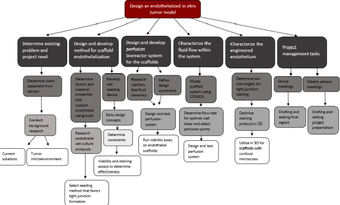
3.5.2 Objective Tree 48
3.5.3 Financial Statement 49
CHAPTER 4 -- DESIGN PROCESS 51
4.1 Needs Analysis 51
4.1.1 Prioritization of Tasks 51
4.1.2 Technical Constraints of the in vitro Tumor Model 53
4.2 Concept Maps/Concept Designs/Prototyping/Modeling/Feasibility Studies 54
4.2.1 Conceptual Designs 54
4.2.2 Preliminary Feasibility Studies 57
4.2.3 Design Calculations 58
4.2.4 COMSOL Model as a Computer Based Simulation 59
4.2.5 Conceptual Designs 61
CHAPTER 5 -- DESIGN VERIFICATION 65
5.1 Silk Scaffold Mechanical Testing 65
5.2 Cell Culture and Viability Testing 69
5.2.1 Resazurin Impact on Cell Viability and Proliferation 70
iii
5.2.3 CD31 Immunostaining for Endothelial Tight Junction Formation 72
5.3 Verification of Perfusion Bioreactor System 78
5.3.1 COMSOL Verification for Fluid Flow 78
5.3.2 Initial Bioreactor Setup 79
5.3.3 Bioreactor Fluid Flow 80
5.3.4 Bioreactor Fluid Dynamics Analysis 81
5.3.5 SolidWorks Fluid Simulation and Wall Shear Stress Calculation 82
5.3.6 Resazurin Fluorescence Intensity after 7 Days for Static and Dynamic Cultures 86
5.3.7 Confocal Microscopy Tight Junction Verification 88
5.3.8 Analysis and Comparison of the Static and Dynamic Collagen-Embedded Scaffolds 89
5.3.9 Sterility and Biocompatibility of Bioreactor 90
CHAPTER 6 -- FINAL DESIGN AND VALIDATION 94
6.1 Final Design 94 6.2 Industry Standards 97 6.3 Project Impact 98 6.3.1 Economics 98 6.3.2 Environmental Impact 99 6.3.3 Societal Influence 100 6.3.4 Political Ramifications 100 6.3.5 Ethical Concerns 100
6.3.6 Health and Safety Issues 101
6.3.7 Manufacturability 101
6.3.8 Sustainability 103
CHAPTER 7 -- DISCUSSION 104
7.1 Design of a Method for Scaffold Endothelialization 104
7.2 Characterization of Perfusion Bioreactor System for Dynamic Culture 106
CHAPTER 8 -- CONCLUSIONS AND RECOMMENDATIONS 107
8.1 Conclusions 107
8.2 Recommendations 107
REFERENCES 110
APPENDICES 117
Appendix A: Stress/Strain Curves for Mechanical Testing of Silk Scaffolds 117
Appendix B: Resazurin Impact on Cell Viability and Proliferation Protocol 124
iv
Appendix D: Silk Extraction Protocol 127
Appendix E: Fluid Dynamics Calculations and Modeling for Bioreactor System 130
Appendix F: SolidWorks Flow Simulation Protocol 131
Appendix G: ATCC TIME Endothelial Cells Passaging Protocol 136
Appendix H: Silk Scaffold Seeding Protocol for Half Moon Geometry 137
Appendix I: Collagen Gel Formulation 138
v AUTHORSHIP PAGE
Primary Author Primary Editor
CHAPTER 1 - INTRODUCTION All Nicole Chittim
CHAPTER 2 - LITERATURE REVIEW 2.1 Metastatic Cancer
2.2 Blood Vessel Anatomy and Classification
2.3 Tumor Model Research 2.4 Blood Fluid Dynamics 2.5 Perfusion Bioreactor McKenzie Brunelle Emily Newman Nicole Chittim Emma Sheils Ryan Conlan Ryan Conlan Nicole Chittim
CHAPTER 3 - PROJECT STRATEGY 3.1 Initial Client Statement
3.2 Technical Design Requirements 3.3 Design Requirements (Standards) 3.4 Revised Client Statement
3.5 Management Approach Professor Coburn Emily Newman Nicole Chittim Nicole Chittim Emma Sheils McKenzie Brunelle McKenzie Brunelle
CHAPTER 4 - DESIGN PROCESS 4.1 Need Analysis
4.2 Concept Maps/Concept
Designs/Prototyping/Modeling/Feasibility Studies
Nicole Chittim
Nicole Chittim and Emma Sheils
Emily Newman
CHAPTER 5 - DESIGN VERIFICATION 5.1 Silk Scaffold Mechanical Testing 5.2 Cell Culture and Viability Testing 5.3 Verification of Perfusion Bioreactor System McKenzie Brunelle Nicole Chittim Ryan Conlan Emily Newman Emma Sheils Emma Sheils
CHAPTER 6 - FINAL DESIGN AND VALIDATION 6.1 Final Design 6.2 Industry Standards 6.3 Project Impact Nicole Chittim McKenzie Brunelle All All
CHAPTER 7 - DISCUSSION Emily Newman Emma Sheils
CHAPTER 8 - CONCLUSIONS AND RECOMMENDATIONS 8.1 Conclusions 8.2 Recommendations Nicole Chittim Nicole Chittim McKenzie Brunelle
vi ACKNOWLEDGEMENTS
The team would like to thank our advisor, Professor Jeannine Coburn, and Kimberly Ornell for their guidance and assistance with the project. We would also like to thank lab managers Elyse Favreau and Lisa Wall for their assistance ordering supplies and finding an appropriate instrument for compression testing. Additionally, we would like to thank Dr. Sakthikumar Ambady for providing us with cells, Dr. Adriana Hera for providing assistance with modeling, and Hannah Strobel for her guidance regarding cell staining, cell imaging, and the use of the peristaltic pump. We also greatly appreciate Alycia Abbott, Elzani van Zyl, Nhi Phan, and Natalia Vargas Montoya for their continued support. Finally, we would like to thank Worcester Polytechnic Institute for providing the facilities and funding for the project.
vii ABSTRACT
Cancer amounts to about 600,000 deaths per year [1]. In advanced cases of the disease, the tumor vasculature permits systemic circulation of tumor cells to secondary tissue sites resulting in metastasis. Developmental oncological drugs require testing on platforms that are representative of the human tumor microenvironment. Animal models offer varying signaling pathways that create a translational gap between testing and clinical results. Current in vitro
testing systems do not accurately mimic the tumor microenvironment as they lack a consistent endothelial monolayer and controllable fluid flow. Poor quality models result in an 8% success rate of drugs in clinical trials [2]. We propose a novel tumor model composed of a lyophilized 10% silk scaffold cultured with an endothelial cell monolayer in a perfusion bioreactor system to control fluid flow rate and mimic mechanics of a capillary. Preliminary data confirmed the development of a viable endothelial scaffold in a sterile, reperfusable bioreactor system, which is promising for future co-culture applications and in vitro oncological drug testing.
viii TABLE OF FIGURES
Fig. 2.1 Schematic of intravasation of tumor cells from the epithelial tissue through the endothelium resulting in tumor migration to secondary tumor sites [9].
Fig. 2.2 Diagram indicating blood transport of oxygenated and deoxygenated blood and capillary mediated flow through major organ system [18].
Fig. 2.3 Tight, gap and adherens protein complex structures in endothelial cells [19]. Fig. 2.4 Hypoxia response for angiogenesis in the tumor microenvironment [26].
Fig. 2.5 Schematic detailing intravasation of tumor cells into the bloodstream through the endothelial monolayer of capillary vessels.
Fig. 2.6 Illustration of the implantation of a tumor model into a mouse. This illustrates the location at which the scaffold was implanted into the murine model, as well as the two histological sections that were used to analyze the results of the study [30].
Fig. 2.7 Illustration of the formation of a 3D tumor spheroid, beginning with tumor cells. These cells were then cultured using the hanging drop method to form 3D tumor spheroids [36]. Fig. 2.8 Fluorescent microscopy image of a hyaluronic acid hydrogel 3D tumor culture. In this study, cells were stained with phalloidin for F-actin, which shows the structure and function of the cells. These tumor culture cells were cultured on a hyaluronic acid hydrogel for two days [38].
Fig. 2.9 Schematic of microfluidic system with endothelial (green), tumor (red) and ECM (gray) components [41].
Fig. 2.10 Schematics illustrating the different types of fluid flow (a) in a pipe and (b) in a channel [44].
ix Fig. 2.11 Simple perfusion bioreactor system [48].
Fig. 2.12 Closed loop perfusion bioreactor system [48].
Fig. 2.13 Hollow fiber bioreactor system with cells grown on the outside of the fibers and media perfused throughout the hollow fibers [48].
Fig. 2.14 Direct perfusion bioreactor system [48]. Fig. 2.15 Current Coburn lab bioreactor system.
Fig. 3.1 Gantt chart for project design and development process.
Fig. 3.2 Work breakdown structure for in vitro endothelialized tumor model. Fig. 3.3 Estimated financial breakdown for project budget.
Fig. 4.1 Concept map for in vitro endothelialized tumor model.
Fig. 4.2 COMSOL model depicting the flow pattern around the scaffold in the pipe system of the perfusion bioreactor.
Fig. 4.3 Three-dimensional COMSOL model depicting the tubing and scaffold holder of the bioreactor.
Fig. 4.4 Current bioreactor system used in the Coburn lab, including scaffold holder. Fig. 4.5 Peristaltic pump bioreactor conceptual design.
Fig. 4.6 Proposed cell seeding geometries.
Fig. 5.1 Elastic region of stress-strain curve for each percentage of silk composition graphed in relation to the target stiffness of 10 kPa.
Fig. 5.2 Effect of resazurin exposure on cell proliferation and viability expressed in fluorescence count measurements as represented by the average of four replicates.
Fig. 5.3 Resazurin reading on collagen silk, Matrigel silk, collagen, Matrigel and TCP surfaces on Day 3 and Day 7 in vitro.
x Fig. 5.4 A) Primary antibody control for the protocol in Appendix C Part A using TIME
endothelial cells Day 7 in vitro with Hoechst (blue) and CD31 (red). B) Primary antibody control for the protocol in Appendix C Part B using TIME endothelial cells Day 7 in vitro with Hoechst (blue) and CD31 (red).
Fig. 5.5 Alexa-Fluor 568 goat anti-rabbit secondary antibody (red) control for staining protocol outlined in Appendix C Part A and Appendix C Part B using TIME endothelial cells Day 7 in vitro.
Fig. 5.6 Immunostaining of TIME endothelial cells Day 7 in vitro with Hoechst (blue), phalloidin (green) and CD31 (red) using protocol from Appendix C Part A.
Fig. 5.7 Immunostaining of TIME endothelial cells Day 7 in vitro with Hoechst (blue), phalloidin (green) and CD31 (red) for Appendix C Part B protocol.
Fig. 5.8 Immunostaining of TIME endothelial cells in vitro with Hoechst (blue), phalloidin (green) and CD31 (red) using optimized Appendix C Part B protocol.
Fig. 5.9 COMSOL model illustrating an increase in fluid force around the scaffold with an increased inlet velocity.
Fig. 5.10 Initial bioreactor testing with blue food coloring.
Fig. 5.11 Schematic of tubing order and dimensions used for fluid dynamics calculations. Fig. 5.12 Heat map of scaffold surface detailing distribution and magnitude of wall shear stress in the Swinnex scaffold holder at a volumetric flow rate of 0.4 mL/s.
Fig. 5.13 Heat map of scaffold surface detailing distribution and magnitude of wall shear stress in the Swinnex scaffold holder at a volumetric flow rate of 0.4 mL/s for the modified silk scaffold geometry.
xi Fig. 5.14 Heat map of scaffold surface detailing distribution and magnitude of wall shear stress in the Swinnex scaffold holder at a volumetric flow rate of 0.07 mL/s for the modified silk scaffold geometry.
Fig. 5.15 Fluorescence intensity readings for Day 0 and Day 7 for static and dynamic culture conditions.
Fig. 5.16 Confocal image of statically cultured endothelial cell monolayer at 10X with Hoechst nuclear stain (blue) and phalloidin extracellular matrix stain (green).
Fig 5.17 10X Confocal microscopy images for static endothelial culture (left) and bioreactor endothelial culture (right) with Hoechst nuclear stain (blue), phalloidin extracellular matrix stain (green) and AdipoRed (silk) stain.
Fig 5.18 A) 10X brightfield image prior to first media change. B) 10X brightfield image on Day 3 after media exposure for collected bioreactor medium. C) 10X brightfield image on Day 3 after media exposure for regular vascular endothelial growth medium.
Fig 5.19 Resazurin fluorescence for bioreactor and regular vascular growth medium after 7 days of exposure normalized to baseline readings.
Fig. 6.1 10% silk scaffold cut to a half moon with endothelial cells seeded on it. The scaffold is inserted into the 2 mm thick PDMS ring, which is then inserted into the Swinnex.
Fig. 6.2 A) Tubing being pulled through the 3 mm holes that were biopsy punched in the septum cap of the media vial. B) Media vial filled with media showing how the tubing sits in the vial.
Fig. 6.3 Media vial with air filter and 60 mL syringe connected. This image illustrates how the tape was used to ensure constant pressure in the system.
xii Fig. 6.4 Setup of the bioreactor outside of the incubator showing the perfusion pump and closed loop system of tubing and media.
Fig. 6.5 Setup of the bioreactor inside of the incubator showing the perfusion pump and closed loop system of tubing and media.
xiii TABLE OF TABLES
Table 2.1 Common sites of metastases [14].
Table 3.1 Objectives for the endothelium categorized by engineering discipline. Table 3.2 Design constraints for endothelialized scaffold.
Table 3.3 Design objectives for the bioreactor system. Table 3.4 Bioreactor design constraints.
Table 4.1 Pairwise comparison chart for project.
Table 4.2 Different concepts for each design function of the project. Table 5.1 Elastic modulus for 3%, 6% and 10% silk scaffolds. Table 5.2 Results from ANOVA analysis of mechanical testing data.
Table 5.3 Results from SPSS Bonferroni correction showing the statistical significance between each group.
Table 5.4 Bioreactor volumetric flow rate measurements.
Table 5.5 Mass flow rates and fluid velocity for 40 rpm, 60 rpm and 100 rpm peristaltic pump settings.
Table 5.6 Average wall shear stress and volumetric flow rates in the scaffold holder for 40 rpm, 60 rpm and 100 rpm peristaltic pump settings.
1 CHAPTER 1 -- INTRODUCTION
Statistical analysis of United States pharmaceutical companies discovered that the research and development costs to produce one oncology drug exceed $650 million [3]. In addition to high production costs, about 85% of early stage clinical trial candidates fail before being tested in the clinic [4]. This high failure rate is due in part to the translational gap between current in vitro human tumor models and clinical performance [3]. New oncological drugs are currently tested using three-dimensional (3D) cell culture utilizing either a hydrogel scaffold or a tumor spheroid system [5]. Prior to use in human subjects, drug efficacy and toxicity can be analyzed in rodent models [3]. However, in addition to ethical considerations regarding animal use, these models fail to reflect the extracellular stromal component and relevant cytokine signaling pathways present in human tissue, which are important in
promoting the vascularization of the tumor [3]. To replicate a portion of the tumor environment in an in vitro model, this project aimed to develop an endothelialized scaffold for future
coculture with neuroblastoma cells. The scaffold needed to provide 3D supporting architecture for both the endothelial and neuroblastoma cells. Neuroblastoma cells are ideal for modeling a solid tumor because they are phenotypically diverse, heterogeneous, and often prone to
metastasis due to their early onset and prevalence along major blood vessels [6]. By mimicking the hierarchical structure of native vasculature, the model provides a more realistic in vitro
testing platform that better mimics a physiologically relevant tumor microenvironment, thus increasing preclinical data translatability and lowering attrition rate.
The ideal scaffold for a device of this nature is biocompatible and offers tunable mechanical properties. Being able to alter the mechanical properties of the scaffold is
2 (~10 kPa) and be compatible with a surface coating to ensure endothelial proliferation and tight junction formation [7]. Possible scaffold materials compatible with 3D culture include silk, collagen, synthetic polyester composite and fibronectin. The goal for the material is to provide a support structure for the adhesion of endothelial cells to a scaffold material to create a viable endothelial cell layer with tight junction occludin and claudin protein complex formation to establish barrier function. The barrier function mimics that of an in vivo endothelial cell layer, providing a more accurate model.
This project aimed to develop a method to seed endothelial cells in a monolayer and ensure even distribution and tight junction formation. Available endothelial cell types include human umbilical vein cells (HUVEC) and TIME cells. HUVEC cells are primary endothelial cells that are derived from the human umbilical vein. TIME cells are an endothelial-like immortalized cell line derived from human foreskin. After deciding on a cell type, the endothelial cells were seeded in a monolayer on the silk scaffold.
Once the cells adhered to the scaffold, the phenotype and function of the
prevascularized cell scaffold was validated using fluorescent microscopy to characterize the endothelial monolayer. Staining was done using an antibody for F-actin, an essential protein for stress fiber formation and barrier function regulation. A metabolic viability assay using resazurin assessed the viability of the engineered endothelium prior to experimental use. In the future, the media concentration levels can be monitored to determine whether the endothelium can successfully regulate transport of molecules into the bloodstream.
To support endothelial cell growth, a perfusion bioreactor was designed to recapitulate capillary bed blood flow and recycle cell media through the prevascularized scaffold material. The goal of the bioreactor system was to recapitulate the cyclic wall shear stress found in blood
3 vessels [8]. The mechanical stimulus provided by the perfusion bioreactor system fostered extracellular matrix production as well as endothelial proliferation [8]. Additionally, the
continuous fluid flow through media reperfusion permitted high flow rates to accommodate for versatile scaffold geometries while eliminating the need to frequently replace cell culture media, ultimately reducing the total cost of model operation.
The bioreactor system required sterilization between each use. To ensure sterilization capability, the materials used were made of material that can be sterilized, either via autoclave or 70% ethylene oxide. In addition to durability at high temperatures and moistures, the system functioned in an incubator to regulate the temperature of the system and ensure cellular
homeostasis at 37 ± 0.5℃.
From a temporal standpoint, the bioreactor needed to be able to support the
endothelialized scaffold for at least seven days to allow for adequate cell proliferation and testing. To supply the tissue, the system needed to contain ports through which depleted media can be drained and replaced.
After the development of the perfusion bioreactor system that effectively supports a prevascularized scaffold, a solid pediatric neuroblastoma cell coculture can be added to
replicate the cytokine signaling present in the tumor microenvironment. Coculturing the model with cancer cells may mimic the diseased state of the endothelium, and will then be an accurate representation of a cancer mass on which pharmaceuticals can be tested. The endothelial cells could be cocultured with other tumor associated cell types, such as fibroblasts and immune cells, to provide a heterogeneous microenvironment that is more representative of the in vivo
tumor. This project presents a perfusion bioreactor system that can support a functional endothelium with tight junction formation. In addition, the prevascularized scaffold could
4 allow for coculture with solid tumor neuroblastoma cells, creating an accurate in vitro
5 CHAPTER 2 -- LITERATURE REVIEW
2.1 Metastatic Cancer
Statistics estimated that in the year 2016, cancer caused 595,690 deaths in America, which amounts to about 1600 deaths per day [1]. Metastasis, the process by which cancer cells migrate from the primary site throughout the body, is the principal cause of death in cancer patients [9]. For many patients, by the time cancer is detected metastasis has already occurred, which makes it difficult to implement drug treatments that target specific cancers, therefore requiring the use of potent systemic treatment modalities. When cancer metastasizes to a late stage, surgical, chemical and radiation treatment options cannot effectively treat all tumor growth. Current treatments for metastatic cancer are limited and often inadequate.
During metastasis, cancer cells detach from their primary sites in the tumor and begin to migrate toward lymphatic tissue or blood vessels. Upon reaching a blood vessel, the tumor cells must cross the endothelial barrier to enter circulation in a process known as intravasation. Once in circulation the metastatic cells may be attacked by the immune system or killed by the shear stress induced by the blood. If the cells remain viable in circulation, they are transported to capillaries in a secondary location.
The site of metastatic spread can vary depending on the site of the original tumor and path taken through the circulatory system. Tumor cells may then undergo extravasation and exit the bloodstream, where they migrate into the surrounding tissue and proliferate. The newly formed tumors replicate and undergo angiogenesis, the formation of new blood vessels [10]. The process of cell metastasis and tumor formation is shown in Fig. 2.1.
6 Fig. 2.1 Schematic of intravasation of tumor cells from the epithelial tissue through the endothelium
resulting in tumor migration to secondary tumor sites [9]. Reprint with permission from Annual Reviews.
2.1.1 Classification of Metastatic Tumors
Cancer cells can be classified as a metastatic or a non-metastatic phenotype. Tumors made up of non-metastatic cells are considered benign while those tumors that consist of both metastatic and non-metastatic cells are considered malignant [11]. The chance of a patient having a malignant tumor varies widely depending on the location. For example, 80% of discovered breast masses are found to be non-cancerous or benign [12] while only 5-10% of gastric tumors are benign [13].
The locations of tumor origins can affect the locations to which they spread. Many types of cancer have organ-specific patterns of metastasis. For example, breast cancer
frequently spreads to the bones, lungs, liver, and brain. Table 2.1 shows some of the common sites of metastatic tumors and their sites of spread. There are two main reasons for this organ-specific metastasis. The first is that vascular pathways limit and control the areas to which
7 these tumors can spread. The second is that there is a “seed-soil” compatibility between the cancer cells and the location to which they are spreading [14]. Therefore, while an organ may lie along the vascular path of the tumor cell, that organ may not support the growth of that type of cancerous cell.
Table 2.1 Common sites of metastasis [14].
Site of original tumor Site of spread
Neuroblastoma Bone, lymph nodes, liver
Breast Bone, lung, liver, brain
Colorectal Liver, lung, peritoneum
Lung Other lung, brain, bone, liver
Ovary Lung, liver, peritoneum
Prostate Liver, lung, adrenal glands, bone
Stomach Liver, lung, peritoneum
Bladder Lung, liver, bone
Uterus Vagina, peritoneum, liver, lung,
Bladder Bone, liver, lung
Thyroid Liver, lung, bone
Melanoma Skin, muscle, bone, brain, liver, lung
2.1.2 Pediatric Neuroblastoma
Neuroblastoma (NB) is the most common extracranial solid tumor in pediatric patients, representing 7% of childhood malignancies [15]. It is most common for NB to develop within the first year of life; however, NB may arise in adult patients at a significantly less rate of incidence. About 1 in 100,000 children per year are diagnosed with NB, while only 1 in 10 million adults are diagnosed with NB annually [16].
NB arises from the malignant transformation of sympathetic neuroblasts, which are primitive neural cells [17]. It is an extremely heterogeneous cancer type, as some tumors may spontaneously regress while others are aggressively metastatic. NB tumors most commonly
8 develop in the adrenal glands or peripheral sympathetic ganglia then metastasize to other locations. The adrenal system is highly vascularized, providing increased blood vessels and resulting surface area for tumors to efficiently migrate throughout the body. NB is ideal for modeling solid tumors due to its embryonic origins, phenotypic diversity, ability and likelihood to metastasize, and prevalence along major blood vessels [6].
2.2 Blood Vessel Anatomy and Classification
Blood vessels can be divided into three categories: arteries, capillaries, and veins. Arteries transport oxygenated blood from the heart throughout the body and veins carry deoxygenated blood back to heart [18]. Of these vessels, capillaries primarily deliver oxygen and nutrients to tumor masses in the epithelial tissue. Gas and nutrient exchange between the blood and surrounding tissue occurs in capillary vessels that are located in structures referred to as capillary beds, which can be seen in Fig. 2.2 [18]. Capillary vessels do not exceed 4-9 μm in diameter and contain a thin, flat layer of cells known as endothelial cells which create a tight barrier between the blood vessel lumen and surrounding tissue [19]. These permeable vessels allow for the selective transport of nutrients from the bloodstream to major organ systems and tissues of the body.
9 Fig. 2.2 Diagram indicating blood transport of oxygenated and deoxygenated blood and capillary mediated
flow through major organ systems [18]. Reprint with permission from OpenStax.
2.2.1 Protein Junction Complexes of the Endothelium
Endothelial cell adhesion and communication are modulated by three types of protein complexes known as gap junctions, adherens junctions and tight junctions [20]. Gap junctions are composed of connexin proteins that modulate ion transfer for intercellular communication within the endothelium [21]. Adherens junction proteins are dominated by vascular
endothelial-cadherin (VE-cadherin) which provide a site for endothelial cell attachment and adhesion to one another [22]. These complexes, seen in Fig. 2.3, are concentrated around the basal lamina to facilitate adhesion of the endothelial cells to the basal membrane and secure the endothelium [20]. Tight junctions consist of claudin, occludin and other protein units anchored by actin filaments in the endothelial cells [20]. These proteins are responsible for regulating barrier function across the endothelium. Disruption of these complexes results in increased permeability of the endothelium [20]. Tight junctions also influence migration of leukocytes from the bloodstream to the surrounding tissue [22]. Leukocytes, or white blood cells, circulate
10 to areas of infection or inflammation to facilitate an immune response [22]. In disease states the extravasation of leukocytes can inhibit endothelium function due to the induced disruption to the endothelial intercellular junctions [20].
Fig. 2.3 Tight, gap and adherens protein complex structures in endothelial cells [19]. Reprint with permission from Elsevier.
2.2.2 Endothelial Barrier Function
Endothelial tight junctions consist of claudin, occludin and JAM protein complexes [23]. These protein complexes serve as transport complexes and ion channels that can regulate permeability into the blood vessel lumen. Integral proteins within the tight junction complex possess the ability to determine size and charge of ions attempting to cross the membrane [23]. Endothelial transport favors small molecules with no charge. Therefore, disruption of the pH or concentration of surrounding molecules can influence the behavior of the tight junctions [23].
Several extracellular proteins interact with the protein complexes and can support the function of both adherens junctions and tight junctions. Among these adhesive proteins within the extracellular lumen of the endothelial layer, platelet endothelial cell adhesion molecule
11 (PECAM) contributes to the integrity of endothelial barrier function [22]. Current knowledge of the mechanism of action of PECAM is limited to its role in cell anchorage in the basal lamina.
Extracellular proteins such as PECAM support tight junctions through cytokine signaling interactions and pathways. However, the mechanism of how the protein transmits signals in extracellular space is unknown [22]. Murine gene expression experimentation demonstrated that animals expressing inactivated PECAM proteins exhibited increased endothelial permeability over the control indicating that PECAM signaling influences the structure and function of endothelium [20]. PECAM complexes and other integral proteins associated with tight junction formation can be modified in response to cytokine signaling pathways. One major pathway that influences endothelial cell growth and differentiation is the angiogenesis pathway in response to low oxygen conditions in vivo [23].
F-actin contributes to the structural integrity of the tight junction. In a confluent endothelial monolayer, F-actin is expressed around the individual cell perimeter. This actin ring is referred to as cortical actin which provides structural stability to the protein junction [24]. In addition, stress fibers composed of F-actin form within endothelial cells and provide a location for protein adhesion [24]. Essential tight junction proteins adhere to the surface of the actin making actin essential in endothelial permeability [24].
2.2.3 Hypoxia in the Tumor Microenvironment
Hypoxia is the deprivation of oxygen in living tissue. The rapid metabolism and proliferation of tumor cells consumes more oxygen than the existing vasculature can supply to the tumor environment, resulting in hypoxia. In response to these low oxygen levels, hypoxia signaling pathways initiate to promote angiogenesis and restore oxidative balance to the target
12 area [25]. These pathways can be seen in Fig. 2.4. The transcription factor hypoxia inducible factor 1 (HIF-1) dictates the major mechanisms responsible for maintenance of oxygen homeostasis. Oxygen regulation is modulated by the alpha domain of the HIF-1 transcription factor [23]. In the presence of sufficient oxygen levels, HIF-1 degrades via proteasome activity at the alpha subunit and does not initiate transcription of angiogenesis pathway cytokines [23].
Fig. 2.4 Hypoxia response for angiogenesis in the tumor microenvironment [26].
In low oxygen conditions (between 0.5% and 6% oxygen), HIF-1ɑ does not degrade and the transcription factor enters a state of activation [26]. Once activated, expression of growth factors occur which includes but are not limited to, ephrins, platelet derived growth factor (PDGF), angiopoietin 1 and 2, vascular endothelial growth factor (VEGF) and basic fibroblast growth factor (bFGF) [26]. The interaction of these cytokine signals contributes to increased endothelial cell proliferation, chemotaxis, and migration of newly formed vessels [25]. Angiogenesis actively attempts to restore homeostasis to keep the rapidly dividing tumor oxygenated. As angiogenesis accelerates to support the growing tumor the production of
13 excessive and damaged endothelium increases [26]. The defective endothelium increases permeability of the cell layer and increases the chances of tumor cell intravasation into the bloodstream.
2.2.4 Intravasation
Intravasation, the entry of cells into lymphatic or blood vessels, is a process that is important for normal cells as well as tumor cells. Intravasation is necessary during
development, immune response, and signaling [27]. During normal intravasation, vessel
structure and integrity is maintained due to the retention of tight junctions. However, this is not always the case for tumor intravasation which may result in altered endothelial phenotypes and the disruption of tight junctions.
The majority of tumors enter circulation through blood vessels. Intravasation may be active or passive, depending on the structure of the vessel and the tumor microenvironment, and there are a number of identified molecular pathways for intravasation to occur. During metastasis, the tumor cells cross the endothelial cell monolayer of capillaries, as shown in Fig. 2.5.
Fig. 2.5 Schematic detailing intravasation of tumor cells into the bloodstream through the endothelial monolayer of capillary vessels.
14 Several growth factors and signaling pathways such as HIF1 and downstream proteins are necessary for increased endothelial permeability in response to external stimuli. Although the proteins have been identified, the exact mechanisms of these effects are not fully defined [26]. As a result, blood vessel tumor models and culture techniques have been explored as a means for preclinical drug testing as well as in academia to better understand the mechanisms.
To account for the lack of specificity of chemotherapeutic treatments, some treatments use, among other things, the targeting of angiogenesis signaling pathways to prevent the growth of vasculature to support tumor tissue [22]. These anti-angiogenic agents are
characterized into either monoclonal antibodies, synthetic VEGF receptors or tyrosine kinase inhibitors (TKI) [22]. Bevacizumab is a monoclonal antibody with affinity for the VEGF receptor; binding to these receptors inhibits the downstream blood vessel formation [22]. Synthetic high affinity VEGF receptors have been developed as a potential method of
preventing activation of VEGF mediated angiogenesis and are currently in clinical trials; these synthetic receptors will have a higher affinity for VEGF binding than naturally occurring receptors, therefore preventing angiogenesis [22]. TKIs have been proposed to bind to the catalytic site of other downstream molecules that are involved in the angiogenesis pathway, such as receptor tyrosine kinases (RTKs). These pharmaceutical approaches aim to prevent tumor expansion by slowing or inhibiting blood vessel growth with the tumor tissue.
2.2.5 Immune Cell Migration in the Tumor Microenvironment
In the initial stages of cancer cell signaling, the interaction between tumor cells and immune cells can result in ceased proliferation and apoptosis of cancer cells [23]. Tumor progression initiates an inflammatory response, which recruits immune cells such as macrophages and leukocytes to the tumor microenvironment [21]. During later stages of
15 cancer, neutrophils activate tumor induced cell signaling pathways by trapping the tumor and sending signals to recruit other types of immune cells in a typically unsuccessful attempt to fight the tumor. More recent hypotheses suggest that engaging inflammatory response cells, known as myeloid cells, can contribute to intravasation and tumor metastasis [21].
Macrophages localize to the tumor environment as a result of tumor growth on the basement membrane of the epithelial tissue [23]. These cells are among the first cells to be recruited to the tumor site where they adhere to the tumor and penetrate the tissue mass [21]. Macrophages release cytokines such as epidermal growth factor (EGF) which increases proliferation and vascular endothelial growth factor (VEGF). The increase in neighboring cell signaling, or paracrine signaling, increases both tumor growth and angiogenesis, respectively [23]. Thus, the presence of macrophages increases the rate of proliferation of the tumor while increasing blood supply to the mass which can expedite tumor metastasis.
Leukocytes, or white blood cells, are a type of immune cell that play an integral role in the inflammatory response. One type of leukocyte, known as a lymphocyte are signaled to the tumor microenvironment to help with the body’s innate tumor defense mechanism.
Lymphocytes travel through the bloodstream and they can penetrate through the endothelial layer [23]. Lymphocyte penetration disrupts endothelial tight junctions and contributes to metastasis by decreasing barrier function and increasing permeability of tumor cells into the bloodstream [23].
2.3 Tumor Model Research
Currently, there are both in vivo and in vitro tumor models used for preclinical anticancer drug screening. Examples of in vivo models include: orthotopic xenografts, 3D
16 scaffold implants, and humanized models. In vitro models are commonly used as a
prescreening model for in vivo testing. However, the more accurate the in vitro model is, the better the drug will test in vivo, reducing the number of animals needed for accurate results. Examples of in vitro models include: two-dimensional (2D) models, 3D tumor spheroids and 3D tumor cultures. Three-dimensional in vitro models were developed to better mimic the native tumor environment. Each tumor model currently in use comes with its own set of limitations.
2.3.1 In Vivo Models
Some in vivo models consist of a direct injection of tumor cells into the organ from which the cancer being studied originated while others begin with tumor development in a scaffold in vitro to be implanted in vivo. The method of directly injecting tumor cells into an organ, commonly called an orthotopic xenograft, is performed in murine models, and offers a scaffold-free approach to the development of a 3D in vivo tumor model. This method exposes the developing tumor to a similar microenvironment to that of a native tumor. In this model, tumor cells are injected into the animal which allows for metastasis: however, in vivo 3D tumor scaffolds do not exhibit metastasis [28].
As mentioned earlier, this next type of in vivo model begins with the development of a tumor on a scaffold, which is then seeded with a cell type. The scaffold is then implanted into a live model, where it is able to use in vivo conditions such as cell signaling pathways to become a realistic model. A study performed by Girdhari Rijal, et al. implanted 2 mm porous scaffolds into immunodeficient mice after the scaffolds were cocultured with human breast cancer cells. An image depicting the implantation of the scaffolds can be seen in Fig. 2.6. After four weeks, the scaffolds were surgically removed from the murine models and examined. Results showed
17 that the tumor model increased in size and supported proper tumor cell growth in vivo [29].
Fig. 2.6 Illustration of the implantation of a tumor model into a mouse. This illustrates the location at which the scaffold was implanted into the murine model, as well as the two histological sections that were used to
analyze the results of the study [30]. Reprint with permission from John Wiley and Sons.
In a study performed by W. Zhang et al., human umbilical vein endothelial cells (HUVECs) were used to preseed a scaffold implanted into eight-week-old male nude mice. The purpose of this study was to compare the tissue integration and vascularization rates seen in the scaffold in vitro versus in vivo. The scaffolds were cultured with HUVECs for seven days before being subcutaneously implanted into the mice for three days. It was concluded that blood perfusion rate, vascularization rate, tissue integration and ingrowth of seeded cells increased in the model that was implanted in vivo when compared to the in vitro model [31]. While this was not a tumor study, it provides insight into scaffold and how they behave in vitro
versus in vivo.
A third type of in vivo tumor model is a humanized mouse model. This type of model begins with an immunodeficient mouse, to which human immune function and protein expression is introduced. A humanized model is typically used to exhibit a more accurate human immune response when a tumor is introduced in vivo. These murine models are then
18 used as the recipient of a xenograft of a human tumor. However, once implanted, the human stroma of the tumor is quickly replaced by a mouse stroma. This means that the
endothelialization of the human tumor in the mouse model will change to exhibit that of a mouse; the endothelialization of the tumor will no longer be accurate to that of a human [32].
While in vivo tumor models have been shown to increase vascularization rates and endothelial cell growth when compared to early in vitro models, they also come with certain limitations. Animal models are expensive and can cost anywhere from $11 to $96 per mouse [33]. Humanized mouse models can cost upwards of $1,000 per female mouse [34]. It is also difficult to make large (greater than 12 mm in diameter) tumors since it is being implanted into such a small animal [30]. Orthotopic tumor models tend to be difficult to develop with a need for assistive imaging methods to monitor the growth of the tumors [28]. Using murine models is an acceptable form of experimental testing; however, mouse biology does not completely replicate human tumor biology. Limitations in animal models exist regarding their ability to accurately mimic human physiology and cancer metastasis resulting in an 8% success rate in the transition from animal models to clinical trials of cancer drugs [2]. In addition to the problems relating to data comparability, it is more humane to use in vitro models to minimize
in vivo animal testing.
2.3.2 In Vitro 2D Tumor Models
The most basic in vitro tumor model is a 2D model: this is a 2D platform that consists of a single endothelial monolayer in a culture plate. This type of model is useful in studying the migration of cancer cells across a membrane. When compared to other in vitro tumor models, the 2D model is inexpensive, and it is relatively quick to make and test, making it a valid option for studying the migration of the cancer cells. However, these models do not accurately
19 mimic tumor cell protein or gene expression, nor do they offer a hierarchical endothelial
structure. Additionally, these cultures only model two dimensions of a tumor that is 3D in reality [35].
2.3.3 In Vitro 3D Tumor Spheroids
The use of 3D tumor spheroids is an effective alternative to monolayer in vivo tumor modeling. These models consist of a complex 3D spheroidal aggregation of cancer cells, as seen in Fig. 2.7. These models can be used to see relatively accurate effects of certain drugs on cancer cells. Models that are currently in use have biomimetic qualities and exhibit many biologically accurate characteristics, such as growth kinetics, physiological nutrient supply and pH distribution. They also have tissue-like properties, including compactness and chemical gradients. Additionally, they can model cell to cell and cell to matrix interactions [36]. Current models also mimic interactions between cancer and stromal cells, and extracellular matrix [37].
Fig. 2.7 Illustration of the formation of a 3D tumor spheroid, beginning with tumor cells. These cells were then cultured using the hanging drop method to form 3D tumor spheroids [36].
Reprint with permission from Elsevier.
2.3.4 In Vitro 3D Synthetic Polymer and Hydrogel Tumor Models
In vitro 3D scaffold based tumor models are an alternative currently used to in vivo
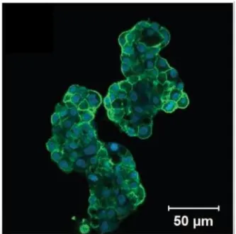
20 The models commonly include an extracellular matrix component [38]. When the scaffold is cultured with cancer cells and a hyaluronic acid hydrogel, the tumor cultures exhibit invasion and proliferation of the cancer cells throughout the model, which can be seen in Fig. 2.8. The microenvironment created by the 3D tumor model is favorable for the invasion, proliferation and migration of malignant cells, and accurately represents that of in vivo conditions [39].
Fig. 2.8 Fluorescent microscopy image of a hyaluronic acid hydrogel 3D tumor culture. In this study, cells were stained with phalloidin for F-actin, which shows the structure and function of the cells. These tumor
culture cells were cultured on a hyaluronic acid hydrogel for two days [38]. Reprint with permission from Elsevier.
One example of a 3D tumor culture is a hyaluronic acid hydrogel, which can be
cultured with a prostate cancer cell line. These hydrogels were plated on a tissue culture plastic surface. Adequate cell cluster formation and viability was observed over a seven-week period. Then these cultures were used to test cancer therapy drugs [38]. Another example of a 3D tumor culture was made of a hyaluronan hydrogel, which is different from the previously mentioned hyaluronic acid because it lacks the acid component. This hydrogel was cultured
21 with a lung cancer cell line, which then formed a homogeneous distribution throughout the hydrogel. From there, the cultures were used to determine the efficacy of cancer therapy drugs [39].
Another example of a 3D tumor model uses a collagen scaffold. Collagen is a very common protein in the body and its main function is to provide stability to many tissues. Collagen is extracted from both human and animal tissues to be used as a biomaterial. Due to collagen’s biocompatibility, controlled biodegradability and its ability to be prepared in various forms it is considered to be a suitable biomaterial for tissue engineering and other applications [40].
2.3.5 In Vitro Limitations
One major drawback to an in vitro tumor model, in general, is that it does not
accurately reflect the 3D organization of the in vivo tumor endothelial environment. While this is an important limitation to consider, it is also important to note that it is not practical to go straight to in vivo testing without first testing in vitro [31]. In vitro 3D tumor models are usually made from a synthetic scaffold like a hydrogel or polymer, which does not provide the same extracellular cues that would occur naturally in vivo. Additionally, because these models tend to be synthesized from biological sources, they have a composition that is variable and therefore irreproducible [38].
Another major drawback to the current in vitro tumor models is the accuracy to which they model the endothelial layer. Some in vitro models have been co-cultured with endothelial cells to mimic cell signaling [31]. However, a mixed coculture of cells does not allow proper endothelialization of the model. These models still lack a hierarchical endothelial structure, as would be seen in vivo. Some models attempt to incorporate an endothelial cell barrier;
22 however, these typically consist of an endothelial monolayer on the surface of the scaffold which cannot penetrate through the model to model angiogenesis [41].
2.3.6 Microfluidic Devices
In vitro models have been improved using microfluidic devices. Recent advances in the field of microfluidics allows for precise control over fluid flow in microchannel structures. The use of these devices has help create more physiologically precise models.
Microfluidic systems have independently addressable channels that provide ideal models for capillary blood flow. Microfluidic tumor models are also being used to study tumor metastasis in vitro [41]. The independently addressable channels offer a significant advantage in that it allows for the device to have a distinct endothelial and tumor component as displayed in the Fig. 2.9. The separation of these components allows for tissue formation and cell
communication between the channels of the microfluidic device. Assays of this nature have been used to determine the effect of various growth factors and cytokines on tumor cell
migration and endothelial cell morphology [42]. In addition to cytokine signaling, microfluidic devices allow for small scale exposure to fluid shear stresses that allow for the modeling of endothelial cell stress response. Changes in these shear stresses affect vascular stability and aid in the angiogenesis of tumors [43]. These devices allow for determination of response but neglect to reflect the hierarchical tissue organization, such as the endothelium and common nutrients present in blood vessels within the body.
23
Fig. 2.9 Schematic of microfluidic system with endothelial (green), tumor (red) and ECM (gray) components [41].
Reprint with permission from PNAS.
2.4 Blood Fluid Dynamics
In order to effectively model the in vitro conditions of tumor endothelialization, growth, and metastasis, it is important to understand the basics of fluid mechanics so that the device can recapitulate capillary blood flow.
2.4.1 Flow Characterization
Fluids are defined as liquids and gases that are capable of motion. As these fluids move, they are subjected to forces within themselves, as well as from external sources such as walls and boundaries. Important parameters for fluid flow characterization include density (𝜌), viscosity (𝜇), pressure (P), velocity (V), diameter (D), radius (r), mass flow rate (𝑚̇), volumetric flow rate (𝑉) ̇and cross-sectional area (A).
Fluid flow is characterized as laminar, transitional, and turbulent using the
dimensionless Reynolds number (Re). In laminar flow, the streamlines, created by flow are parallel to each other and do not mix or fluctuate. With transitional and turbulent flows,
24 varying levels of mixing and disturbance of streamlines are determined by the geometry,
roughness, velocity, temperature, and type of fluid [44]. The extent of the turbulence in a flow pattern is quantified by the Reynolds number. The Reynolds number is the ratio of the inertial forces of the fluid to its viscous forces and can be represented as
𝑅𝑒 =𝜌𝑉𝑎𝑣𝑔𝐷 𝜇
where Re is the Reynold’s number, ϱ is the density of the fluid, Vavg is the average velocity of
the fluid, D is the diameter of the tube, and μ is the viscosity of the fluid.
For a channel, the diameter can be replaced with Rh, which is the hydraulic radius. The
critical Reynolds number, Recr is the point at which a flow becomes turbulent. For internal
flow in a circular pipe, this number is 2,300, and it is 500 for channel flow [44]. Thus, Reynolds numbers correspond to flow type as follows. For pipe flow, which is illustrated in 2.10.a [44]:
𝑅𝑒 ≤ 2300→ laminar flow
2300 ≤ 𝑅𝑒 ≤ 4000→ transitional flow
𝑅𝑒 ≥ 4000→ turbulent flow
For channel flow, which is illustrated in 2.10.b [44]:
𝑅𝑒 ≤ 500→ laminar flow
500 ≤ 𝑅𝑒 ≤ 2500→ transitional flow
25 Fig. 2.10 Schematics illustrating the different types of fluid flow A) in a pipe and B) in a channel [44].
Reprint with permission from McGraw-Hill.
2.4.2 Laminar Flow in Pipes
The velocity of a fluid varies across its flow profile because of the no slip condition. The no slip condition states that the velocity of a fluid at the wall of a pipe or channel is zero, and increases to the maximum velocity in the center. Due to this variation, it is most
convenient to perform calculations using the average velocity (Vavg) [44]. The average velocity
of a fluid at any given cross-section is related to the mass flow rate by the following equation, where 𝑚̇ is the mass flow rate of the system, ϱ is the density of the fluid, Vavg is the average
velocity of the fluid, and A is the cross-sectional area of the tube.
𝑚̇ = 𝜌𝑉𝑎𝑣𝑔𝐴
Because of the no-slip condition, a stationary boundary layer is created along the walls of a pipe or channel. Since the fluid molecules are not moving, the fluid moves faster toward the center of the pipe, creating what is called a velocity profile [44]. Once the fluid at the center of the pipe reaches its full speed, the flow is considered fully developed. The entrance length is the measure of how far into the pipe or channel the flow becomes fully developed. In fully developed flow, the velocity profile, or size of the boundary layer, is consistent along the length of the flow, making the opposing shear stress along the wall constant everywhere [44].
26 For laminar flow in pipes, the flow is fully developed, meaning that there is no velocity perpendicular to the motion of the fluid, and there is no acceleration. Because power is
required to push fluid along the entire length of a pipe, there is a pressure drop across the length. This quantity is important to know so that the pump used in the system is powerful enough to maintain a consistent flow. The pressure drop is related to the viscosity of the fluid. Therefore, there would be no pressure loss in a frictionless fluid. The pressure drop can be expressed as 𝛥𝑃 = 𝑃1 − 𝑃2 = 8𝜇𝐿𝑉𝑎𝑣𝑔 𝑅2 = 32𝜇𝐿𝑉𝑎𝑣𝑔 𝐷2 , or 𝛥𝑃 = 𝑓 𝐿𝜌𝑉𝑎𝑣𝑔2 2𝐷 ,
where P1 is the initial pressure, P2 is the final pressure, μ is the fluid viscosity, L is the length
of the tube, Vavg is the average velocity, R is the radius of the pipe, D is the diameter of the
pipe, ϱ is the density of the fluid, and 𝑓 is the Darcy friction factor, 𝑓 =𝜌𝑉8𝜏𝑤
𝑎𝑣𝑔2 [44]. In a
horizontal pipe, the volumetric flow rate can be modeled using Poiseuille’s Law and the same variables as defined above:
[𝑉]̇ = 𝑉𝑎𝑣𝑔𝐴 =(𝑃1−𝑃2)𝑅 2 8𝜇𝐿 𝜋𝑅 2 =(𝑃1−𝑃2)𝜋𝐷2 32𝜇𝐿 = ∆𝑃𝜋𝐷4 128𝜇𝐿 [44].
The Bernoulli equation relates average flow velocity, pressure, and the height (h) of an incompressible, non-viscous liquid. In addition to having a constant density, the flow must also be laminar and irrotational. The Bernoulli equation is useful when modelling flow through a constriction, or through varying heights with respect to gravity (g). The equation is as follows:
𝑃1+12𝜌𝑉12+ 𝜌𝑔ℎ
1 = 𝑃2+12𝜌𝑉22+ 𝜌𝑔ℎ2,
where P1 is the initial pressure, ϱ is the density of the fluid, V1 is the initial velocity, g is
acceleration due to gravity, h1 is the initial height, P2 is the final pressure, V2 is the finale
27
2.4.3 In Vitro Blood Flow
Blood is a non-Newtonian fluid, due to its inhomogeneous composition. It shear-thins, meaning its viscosity decreases with greater applied shear force [45]. Red blood cells are capable of deforming to fit through exceptionally narrow capillaries, giving blood its non-Newtonian characteristics, and complicating its flow. Despite these characteristics, blood is often treated as Newtonian and incompressible when being modeled [45].
In the human body, arterial blood pressure ranges from a maximum (systolic) pressure of 100-140 mmHg to a minimum (diastolic) pressure of 60-90 mmHg [45]. In capillaries, this pressure is about 30 mmHg and 10 mmHg at the arterial and venous ends, respectively [45]. Because of the beating of the heart, blood flow in the body is pulsatile, which means it fluctuates over time as opposed to being steady. However, for simplicity’s sake, it is often modeled as steady for computational purposes. Additionally, flow in vessels is generally laminar, except in the aorta, as violent turbulent flows cause damage to red blood cells and other vessel components [45].
2.4.4 Capillary Blood Flow
Capillaries are much smaller than the larger veins and arteries in the human body. Capillary walls are composed of a single layer of endothelial cells [45]. The flow of blood through them is much different from the blood flow through veins and arteries. There are approximately 1010 capillaries with radii of ~3.5 𝜇m and lengths of ~2 mm, with pressure drops of ~8.2 mmHg [45]. The velocity of the flow through capillaries is approximately 0.22 mm/s [45]. Oxygen and carbon dioxide are diffused across the walls of capillaries, resulting in additional flow and pressure across them.
28 difficult for the flow within them to be completely laminar and steady [45]. The peristaltic pumping of the heart results in non-continuous flow in capillaries, as well as sphincter muscles that only contract every few seconds to help contract feeding arterioles. Since many capillaries are smaller than red blood cells, bolus flow is often observed [45]. In this situation, red blood cells plug up the entire cross section of the vessel, and plasma is trapped between them. These regions move across the capillary in series containing both red blood cells and plasma, truly highlighting the heterogeneous composition of blood [45].
2.5 Perfusion Bioreactor
In order to adequately model an in vitro engineered endothelial layer, the culturing conditions must resemble, as close as possible, the conditions in vivo. This includes the environmental and fluid flow conditions discussed in earlier sections. To accommodate these needs, bioreactors have been used in tissue engineering to control the conditions during cell culture.
2.5.1 Function/Operation
The primary function of a bioreactor system is to allow for the control of one or more environmental or operating factors that can affect the biological process [46]. This includes controlling of temperature, pH, CO2 levels, and the flow of nutrients to ensure the cells are in
an environment that promotes cell proliferation, health, and activity. Bioreactor systems can also be used to mimic the mechanical environment that cells experience, such as the stresses and strains experienced during blood flow [47]. Their ability to perfuse or circulate media into and out of the culture vessel, in most cases, a scaffold, also benefits cell proliferation [48]. More specifically, in the field of tissue engineering, perfusion bioreactors are used to develop
29
in vitro models that provide biochemical and physical regulatory signals to the cells to promote the differentiation of the cells [46].
There are a variety of bioreactors that differ in their configuration or in the application they are used for [46]. In the next section, some of the different types of bioreactor systems will be discussed along with their advantages and disadvantages.
2.5.2 Bioreactor Systems Currently in Use
There are multiple types of bioreactor systems, from simple, one-way bioreactors to continuous perfusion, closed loop bioreactor systems. The simplest design uses a syringe and a gas permeable bioreactor bag that allows the media flow using a syringe pump and collected into a waste container, as seen in Fig. 2.10 [48]. Even though this system has the ability to perfuse media across the scaffold, it lacks the ability to recycle the media, therefore the growth factors, proteins, and other secreted nutrients will be wasted [48].
Fig. 2.11 Simple perfusion bioreactor system [48]. Reprint with permission from Elsevier.
A more sophisticated bioreactor contains a culture chamber, where the scaffold is suspended, with a media reservoir connected in a closed loop which allows for continuous
30 perfusion of the media as seen in Fig. 2.11 [48]. Since the scaffold is suspended in the culture chamber, the media flows around the scaffold and fails to actively perfuse through the interior of the scaffold minimizing the nutrients and oxygen on the interior [48].
Fig. 2.12 Closed loop perfusion bioreactor system [48]. Reprint with permission from Elsevier.
Another type of bioreactor that has been used is a hollow fiber bioreactor, a model of which can be seen in Fig. 2.12. In this system, the cells being cultured are immobilized on hollow capillary-like tubes, which are bundled together inside of a larger tube. It is through the larger tube that the media is perfused [48]. The hollow tubes allow for the capillary-like fluid flow that produces a shear stress on the cells that has been shown to support cell differentiation of certain cell types [48].
31 Fig. 2.13 Hollow fiber bioreactor system with cells grown on the outside of the fibers and media perfused
throughout the hollow fibers [48]. Reprint with permission from Elsevier.
Lastly, the direct perfusion bioreactor, seen in Fig. 2.13. This bioreactor can perfuse the media through the pores and internal networks of the scaffold allowing the delivery of nutrients and removal of waste [48]. The advantage of this system is that the media can perfuse through the interior of the scaffold which increases the viability of the engineered tissue by promoting even distribution throughout the scaffold [48]. Flowing the media through the pores and internal networks of the scaffold also provides the cells with a shear stress, as mentioned before, that supports cell differentiation [48].
32 Fig. 2.14 Direct perfusion bioreactor system [48].
Reprint with permission from Elsevier.
2.5.3 Current Laboratory Apparatus and Limitations
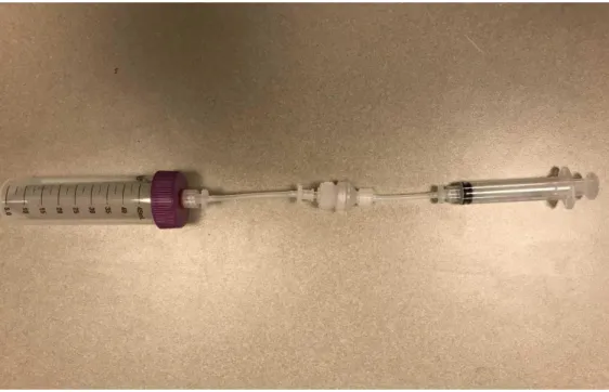
The current bioreactor system being used in the Coburn lab is a simple, one-way bioreactor that operates as indicated in Fig. 2.14. This bioreactor consists of a 5-mL syringe which, along with a syringe pump, is used to perfuse the media through the system. Tubing is used to connect the syringe to the scaffold holding device in the center of the system. A silk scaffold with neuroblastoma cells can be seeded into a porous lyophilized silk scaffold
surrounded by a PDMS ring that is used to create a tight seal along the outside of the channel. The scaffold holding device tubing is connected to a 50-mL conical tube to collect the waste that flows through the system.
33 Fig. 2.15 Current Coburn lab bioreactor system.
The main limitation with this current bioreactor system is that it does not allow for continuous perfusion of the media through the system which would require a large amount of media to achieve high flow rates. Additionally, flow rates are also limited by the diameter of syringe since the cross-sectional area of the syringe or tube was used to calculate the flow rate along with velocity. For this reason, syringe size must be a consideration when determining flow rates.
34 CHAPTER 3 -- PROJECT STRATEGY
3.1 Initial Client Statement
The initial client statement given to the team was to develop a 3D perfusable cancer model that can support complete endothelialization, endothelial cell growth and function.
3.2 Technical Design Requirements
The goal of this project was to develop an in vitro endothelialized tumor model that could mimic the tumor endothelium microenvironment. Enhancing of the physiological relevance of in vitro tumor models may decrease the translational gap between preclinical oncology drug testing and clinical performance while reducing the need for animal models. The design of this in vitro system was accomplished through the completion of the following overarching goals:
I. Design and develop a method for scaffold endothelialization.
II. Design and develop a perfusion bioreactor system for the endothelialized scaffolds that has the ability to trap migrating cells.
The system was then evaluated according to the following sub-objectives: I. Characterize the fluid flow within the system.
II. Characterize the engineered endothelium.
The objectives of this project were divided according to their application to either the bioreactor system or the engineered endothelium tissue model. This separation was performed to account for the different engineering fields required to achieve each deliverable.
35
3.2.1 Objectives for the Engineered Endothelium
Table 3.1 Objectives for the endothelium categorized by engineering discipline.
Objectives Material Science
Support endothelial cell and neuroblastoma cell growth.
To produce a realistic hierarchy model the scaffold material supported endothelial and neuroblastoma growth and adhesion.
Foster endothelial tight junction formation.
Tight junction formation was essential to barrier function and integrity of the endothelium.
Permit fluid flow through scaffold. Fluid needed to be able to flow parallel to the endothelial layer along the scaffold to allow for continuous flow and constant wall shear stress representative of in vivo conditions.
Mechanics
Develop a compatible cell seeding device to ensure uniform endothelial distribution.
Depending on scaffold geometry, a cell
seeding device could be utilized to evenly seed the endothelial layer along the scaffold
surface.
Survive 7 days under standard physiological conditions.
Tissue must withstand 7 days in vitro to permit endothelial cell growth and viability testing.
The engineered endothelium needed to be grown initially as healthy endothelial tissue with established tight junctions that maintain the barrier function of the monolayer. To simulate this healthy state, the endothelium was grown on a scaffold that would support the future coculture of endothelial cells, neuroblastoma cells and potentially fibroblasts. The addition of neuroblastoma coculture could allow for cytokine signaling to naturally increase
36 the permeability and more accurately model the physiological changes induced on the tumor by the endothelium.
One of the major design parameters for the tumor model involved the geometry of the endothelial cell layer. It was necessary for the endothelial cells to form a uniform monolayer with established tight junction formation to regulate both transport into and out of the
engineered model. The endothelial cells would ideally be seeded in a tubular microstructure to simulate the geometry of the capillaries in vivo. However, a monolayer would allow for design simplification and could allow for application of microfluidic channel devices. In addition to the endothelium geometry, the cell type chosen for this layer was an important design
consideration. Telomerase-immortalized microvascular endothelial (Time) cells or human umbilical vein endothelial cells (HUVEC) were considered for the project.
Cell attachment and tight junction formation were essential to the effectiveness of the model. The scaffold material needed to support endothelial adhesion to maintain layer integrity upon introduction of fluid induced wall stress. The scaffold stiffness could not trigger
phenotypic changes to the endothelium and should allow for the cells to retain a flat, confluent single layer.
Depending on the selected geometry, a compatible cell seeding device may be required. This device would provide mechanical rotation of the endothelium immediately following seeding on the scaffold material. The cell seeding device must be operated in a sterile environment within the biosafety cabinet and must also result in even distribution of the endothelium on the scaffold.
![Fig. 2.1 Schematic of intravasation of tumor cells from the epithelial tissue through the endothelium resulting in tumor migration to secondary tumor sites [9]](https://thumb-us.123doks.com/thumbv2/123dok_us/11091032.2996323/21.918.245.647.117.470/schematic-intravasation-epithelial-tissue-endothelium-resulting-migration-secondary.webp)
![Fig. 2.2 Diagram indicating blood transport of oxygenated and deoxygenated blood and capillary mediated flow through major organ systems [18]](https://thumb-us.123doks.com/thumbv2/123dok_us/11091032.2996323/24.918.266.695.107.398/diagram-indicating-transport-oxygenated-deoxygenated-capillary-mediated-systems.webp)
![Fig. 2.3 Tight, gap and adherens protein complex structures in endothelial cells [19] .](https://thumb-us.123doks.com/thumbv2/123dok_us/11091032.2996323/25.918.290.619.275.560/fig-tight-adherens-protein-complex-structures-endothelial-cells.webp)
![Fig. 2.9 Schematic of microfluidic system with endothelial (green), tumor (red) and ECM (gray) components [41]](https://thumb-us.123doks.com/thumbv2/123dok_us/11091032.2996323/38.918.269.590.106.401/fig-schematic-microfluidic-endothelial-green-tumor-ecm-components.webp)
![Fig. 2.10 Schematics illustrating the different types of fluid flow A) in a pipe and B) in a channel [44]](https://thumb-us.123doks.com/thumbv2/123dok_us/11091032.2996323/40.918.150.755.108.314/fig-schematics-illustrating-different-types-fluid-flow-channel.webp)
![Fig. 2.13 Hollow fiber bioreactor system with cells grown on the outside of the fibers and media perfused throughout the hollow fibers [48]](https://thumb-us.123doks.com/thumbv2/123dok_us/11091032.2996323/46.918.198.681.126.413/hollow-fiber-bioreactor-outside-fibers-perfused-hollow-fibers.webp)
![Fig. 2.14 Direct perfusion bioreactor system [48].](https://thumb-us.123doks.com/thumbv2/123dok_us/11091032.2996323/47.918.183.710.117.358/fig-direct-perfusion-bioreactor.webp)