1
Anti-theft vehicle security system with
preventive action
K. A. Mamun1, Z. Ashraf2
1School of Engineering and Physics, The University of the South Pacific Suva, Fiji 2Power Grid Corporation, Power Development Board, Bangladesh
E-mail: mamun_k@usp.ac.fj,zia.pgcb@gmail.com
Abstract— Nowadays rate of vehicle theft is very high all through the world and the situation are even worse in developing country. Therefore, protection of vehicles with an intelligent, reliable, effective and economical system is very important. The existing technologies for vehicle security have a number of limitations including high false alarm rate, easy deactivation and high cost. In this research an Anti-Theft Vehicle Security System (ATV2S) has been design and implemented utilizing sensor-network system which employ Global Positioning System (GPS) and Global System for mobile communication (GSM) technology to track the vehicle. The cutting edge technology of ATV2S is capable to protect, monitor and track the vehicle even within a minute.
KeyWords- Intelligent Vehicle tracking, Microcontroller, GSM
I. INTRODUCTION
Vehicles have become an essential element of our everyday life. Unfortunately, vehicle theft is also increasing day by day. A report prepared by the National Insurance Crime Bureau states that approximately 1.3 million automobiles were stolen in 2003. In 2003 the rate of the vehicle theft was held steady at about 433 cars per 100,000 people [1]. This scenario is even worse nowadays especially in third world country.
Vehicle tracking systems are commonly used by fleet operators for fleet management purpose such as, dispatch, on-board information, routing and security. Other applications include monitoring driving performance, such as an employer of an employee, or a guardian with a young driver. Vehicle security system can be found in consumers vehicles as theft prevention and retrieval device are normally useful after the incident and they are expensive too. Police and Security department can track the signal created by any tracking system to locate a theft automobile. But for country like India, Bangladesh where majority of the stolen vehicles is very hard
to recover because they are dismantled very quickly and sold at black market. In this case anti-theft tracking systems developed by different researchers [1-3] and companies [4-5] are expensive and also create false alarm. Hence this research is developed an Anti-Theft Vehicle Security System (ATV2S) with preventive features.
The device is a composition of auto dialer, DTMF decoder and microcontroller. When an unauthorized movement is detected, an alert will be reported to the owner of the vehicle by an automatic phone alarm as a warning call and the owner will be able to control the vehicle engine from a remote place via mobile phone.
This design will continuously monitor a moving vehicle and report the location of the vehicle on demand. To do these a PIC microcontroller is interfaced to a GSM Modem and a third party GPS receiver and software (i.e. local mobile network carrier).
This proposed system is unlike other tracking systems [6-11] on the market today as it is designed with self-monitoring system. This low cost, smart vehicle tracking system can be successfully implemented in the cities of a developing countries and implementation in a well-planned manner will bring significant revolutionary enhancement in the transportation industry. Furthermore this system is affordable and cost effective for personal users not necessarily for vehicle but also for other assets (i.e. Home, Shop) security system. This paper also proposes further recommendation based on the trial evaluation of the proposed ATV2S. The rest of this paper will describe details of this system development.
II. SYSTEM OVERVIEW
The ATV2S is designed in such a way that it will automatically inform the owner of the vehicle if anybody hits the car or break window or if they try to open the door with
2 duplicate key through cell phone by call. After receiving the phone call the vehicle owner can lock the engine of the vehicle by entering a predefined password to system using mobile phone and the engine of the vehicle will stop immediately. The engine will only unlock if and only if another password from the owner will send through mobile to the ATV2S, in any other condition the vehicle will not start even with the key. Fig. 1 shows the flow chart of the ATV2S.
Fig 1. Overall Flow Chart of the ATV2S.
The main features of the ATV2S are as follows:
1) If this device is installed in a vehicle and then the thief tries to steal that vehicle, the user/owner will be informed with a warning call in his/her mobile phone.
2) Then the user will be able to control the Engine (ON/OFF) from anywhere immediately via his mobile phone.
3) The owner will be able lock/unlock the door from mobile. 4) Furthermore owner of the stolen vehicle will be able to monitor the current location of the vehicle; in case the thief is still able to take out the vehicle
III.SYSTEM DESIGN
In this section the detailed implementation of the system is presented.
a. Hardware and Software Design:
The system can be interconnected with the car alarm system and alert the owner calling to the mobile phone. This ATV2S is a composition of vibration sensor, auto dialer, DTMF decoder, GSM modem and microcontroller.
Software is basically needed for microcontroller. Programming was done by C language by using MikroC [12]. But microcontroller directly can’t understand the programming C language. So the program is converted to machine language [13-14]. Then the code is loaded to the microcontroller by using PICkit 2 Debug Express [15] Software and debugged by using microcontroller loader which allows in-circuit debugging on selected Peripheral Interface Controller (PIC), which is a microcontroller unit (MCUs). In-circuit debugging permits the programmer to execute, analyses, and edit the program while the PICmicro MCU is embedded in the hardware, hence helping the programmer in debugging the hardware and firmware simultaneously. Fig. 2 represents the ATV2S block diagram.
3 b. Related Technology:
For vibration measurement, piezoelectric sensor (accelerometer) suited due to its light weight, easy placement and easy configuration. Microcontroller usage is best for acquiring data. PIC board has been used for this project which has the ability to acquire sensor data, communicate with other devices, and alert the user when unexpected situation (i.e. vehicle breach attempt) is detected.
i. Sensor: Vibration sensor used to trigger the effect of theft alarm. This module is compared with the normally open type vibration sensor module, vibration trigger for longer periods of time, can drive the relay module. SW-420 Motion Sensor Module Alarm (Fig.3) is used for ATV2S. Output of the sensor is directly connected to microcontroller, through single chip microcomputer to detect the high and low level, thus to detect whether there is a vibration environment.
Fig. 3. SW-420 Motion Sensor Module Alarm Sensor Module Vibration Switch.
ii. DTMF Receiver: The M-8870CH is a full DTMF Receiver that integrates both band split filter and decoder functions into a single 18-pin DIP or SOIC package. Manufactured using CMOS process technology, the M-8870CH offers low power consumption (35 mW max) and precise data
handling. Its filter section uses switched capacitor technology for both the high and low group filters and for dial tone rejection. Its decoder uses digital counting techniques to detect and decode all 16 DTMF tone pairs into a 4-bit code.
iii. GSM Modem: A Global system for mobile (GSM) modem is a specialized type of modem which accepts a SIM card, and operates over a subscription to a mobile operator, just like a mobile phone. GSM uses a process called circuit switching. This method of communication allows a path to be established between two devices. Once the two devices are connected, a constant stream of digital data is relayed. GSM networks consist of three major systems the Switching System (SS), The Base Station (BSS) and the Mobile station (MS).
The Switching system is an operative system in which many vital tasks are accompanied, SS systems holds five databases within it, which performs various activities. The major tasks of SS system are to perform call handling and subscriber associated utilities. These databases from SS systems are MSC, EIR, AUC, HLR, and VLR. The MSC in cooperation with Home Location register (HLR) and Visitor location register (VLR), take care of mobile calls and routing of phone calls. Authentication Centre (AUC) is small component which operates the security end of the system and device identity register (DIR) which is another significant database holds vital information regarding cellular equipment.
The base station has key role in cellular communication. BSS are essentially outdoor components and responsible for linking subscribers (MS) to mobile networks. radio transmission is used for all the communication. The Base station is further divided in two systems; such as BTS and BSC. BTS (Base Transceiver station) deals communication utilizing radio transmission with mobile station and BSC (Base station controller) establishes physical link between subscriber (MS) and BTS, then manage and controls functions of it. MS consist of a mobile unit and a smart card which is also referred as a subscriber Identity Module (SIM) card. This card fitted with the GSM Modem and gives the user more personal mobility [4]. The equipment itself is identified by a unique number known as the International Mobile Equipment Identity (IMEI).
The GSM modem used in this ATV2S is SM5100B(Fig. 4).
4 Fig.4. GSM Modem (SM5100B).
iv. Microcontroller: The microcontroller is the heart of this device. It is the interface between the GSM module and the GPS receiver. A microcontroller is a small computing unit on a single integrated circuit encompassing a processor, data memory, A/D converter and programmable input/output interface. In this device the microcontroller is programmed in such a way that it stimulates the GSM modem in call forwarding when a request is send by the user as shown in Fig. 5.
Fig. 5. PIC Microcontroller.
v. GPS Technology: The Global Positioning System (GPS) is the only fully functional Global Navigation System (GNSS). The GPS uses a constellation of between 24 and 32 Medium Earth Orbit satellites that transmit precise microwave signals that enable GPS receivers to determine their location, speed, direction, and time. A GPS receiver receives the signals from at least three satellites to calculate distance and uses a triangulation technique to compute its two dimension (latitude and longitude) position or at least four satellites to compute its three dimension (latitude, longitude and altitude) position. Therefore GPS is a key technology for giving device its position [5]. The final product is shown in Fig.6.
Fig 6. Final Product: ATV2S. IV. SYSTEM OPERATION
The system is controlled with input signal from the vibration sensor which has been placed inside the vehicle and these vibration signals are then decoded as input for the devices (0 and 1) in binary system. The designed system has a tolerance in terms of a relation between vibration and time. If the vibration is repeating frequently more than three times, the system will send an alarm first and then again observe the next vibration and the duration of the vibration. If the vibration frequency is increased or remain same the system will send a final call to the owner with the information that the vehicle owner need to take immediate action about his vehicle. The input and output of the signal is shown in Fig. 7.
Fig 7. ATV2S input and output response.
The system input and output has been controller through micro controller using machine language. The code and commend generated by the device has been shown as follows:
5 # if Q2+Q3 high - RL1 Low + RL3 high (1s)
# if Q1+Q2+Q3 high - RL7 high # if Q4 high - RL 7 Low Details of Relay's function- RL5 – Make call to client
RL1- Activate the security system RL2- Give door lock pulse RL3- Give door unlock pulse RL7- Block the engine function
If the vibration from the system installed in a vehicle increase over 0.6 G, this system will consider a breech attempt for the vehicle and then the alarming system will alert the vehicle owner.
Fig. 8. Alarming system overview.
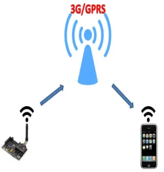
Fig. 8 shows the schematic diagram of how the alert system operates. Alarming technique works using the GPRS system (using the local network) interfaced to the microcontroller. The GPRS shield is a wireless interface for the microcontroller (PIC). The microcontroller has been coded to send out alert messages/calls to the vehicle owner.
V. CONCLUSION AND FUTUREWORK
The advancement of this project is the final product of theft protection device, ATV2S for real time event monitoring with the help of GSM and GPS. The product offers the flexibility to the user to access and monitor the condition of the vehicle and inform any unexpected situation in a user friendly method. Any unexpected occurrence (i.e. Breeching/Breaking) of the vehicle can easily be informed to the ultimate user or even the security department. This project successfully designed and implemented which will ensure more reliability, security and safety for the vehicle owner. Moreover the ATV2S is economical. Furthermore this device can also use by the transportation department for real time fleet monitoring using live traffic map.
REFERENCES
[1] USA Today. (2004) “Top car-theft areas in each state”. [Online]. Available:
http://www.usatoday.com/news/nation/2004/11-29-car-thief-table.htm; Accessed on 01/11/2015.
[2] Sawant Supriya C, Dr. Bombale U. L., Patil T.B,“An Intelligent Vehicle Control and Monitoring Using Arm”, International Journal of Engineering and Innovative Technology (IJEIT), Volume 2 (4), 2012.
[3] Durban, Jack, and Jeffrey J. Lace. "Anti-theft vehicle system", U.S. Patent 6,127,927, issued October 3, 2000.
[4]. Coban, “Anti-theft GPS tracker”, [Online]. Available:
http://coban.manufacturer.globalsources.com/si/6008828124217/p dtl/Car-GPS/1088724352/Anti-theft-GPS-tracker.htm, Accessed on 01/11/2015.
[5] Grameenphone, “Grameenphone Vehicle Tracker apps”, [Online]. Available: http://www.grameenphone.com/personal/vas/mobile-services/vehicle-tracking, Accessed on 01/11/2015.
[6] Garretto, Michael A., Warren AM Howitt, and Edward Vanda. "Anti-theft vehicle system", U.S. Patent 4,991,683, issued February 12, 1991.
[7] Lace, Jeffrey J., and Jack Durban. "Anti-theft vehicle system", U.S. Patent 6,362,728, issued March 26, 2002.
[8] DeLuca, Nicholas Paolo, Alvin L. Ramsey, Edward M. Lee, Patricia Ann Foote, Shin John Choi, and Arlene A. Guerra. "Anti-theft vehicle wheel lock", U.S. Patent 5,689,981, issued November 25, 1997.
[9] Tanaka, Akira, Masaaki Fukamachi, and Kazuhiro Sakata. "Anti-theft system for a vehicle", U.S. Patent 4,965,460, issued October 23, 1990.
[10] Mutoh, Eiji, Susumu Maeda, and Shinichi Kubota. "Vehicle anti-theft engine control device", U.S. Patent 5,606,306, issued February 25, 1997.
6
[11] Stadler, David M. "Automatically armed vehicle anti-theft system", U.S. Patent 5,559,491, issued September 24, 1996.
[12] MicroC, [Online]. Available: http://www.mikroe.com/mikroc/pic; Accessed on 01/11/2015.
[13] Kell, Curtis N., R. Clark Griffin, John M. Dikeman, and Mario D. Nemirovsky. "Programmable vehicle anti-theft system", U.S. Patent 4,990,906, issued February 5, 1991.
[14] M. A. Khalid, K. Kishan, K. Kishen, U. Gounder, P. Chand, U. Mehta, K. A. Mamun, “Design and Development of Low Cost Voice Control Smart Home Device in the South Pacific Region”, Asia-Pacific World Congress on Computer Science and Engineering, 2014.
[15] PICkit™ 2 , [Online]. Available:
http://www.microchip.com/Developmenttools/ProductDetails.aspx ?PartNO=DV164121; Accessed on 01/11/2015