D e pa rt m e n t o f I n f o r m at i c s
Data Structure, Access and Presentation
in Web–GIS for marine research
Author:
Torgeir Mossige G r ø n n i n g
Long master thesis June 2013
I primarily want to thank my supervisor Torill Hamre for great cooperation and advice during my work on the thesis. I would also like to thank the OpenGEO initiative [1] for providing software, documentation and guides without which my work would have been so much harder.
The tools used in the writing of this thesis were: LATEX[2] for typesetting (with the IEEE
citation style [3]), Texmaker [4] as a LATEX–GUI, yEd [5] for general models, Dia [6]
for UML class diagrams and ckwnc [7] for UML sequence diagrams. The base of the LATEXtemplate in use is due to [8] and [9]. Thanks are extended to the creators of and
contributors to these tools and all other free and/or open source software I have employed during my work.
T o r g e i r M o s s i g e G r ø n n i n g Sunday 2nd June, 2013
Acknowledgements ii
Contents iii
List of Figures vii
List of Tables viii
List of Code Listings ix
List of Acronyms xi 1 Introduction 1 1.1 Background . . . 1 1.2 Motivation . . . 1 1.3 Goals . . . 2 1.3.1 Sub–goals . . . 2 1.4 Research questions . . . 3
1.5 Thesis structure and outline . . . 3
2 Problem statement 6 2.1 Elaboration on goals . . . 6
2.2 Research questions . . . 7
2.3 System architecture and requirements . . . 8
2.3.1 Geographic data store requirements . . . 9
2.3.2 Geographic data accessor requirements . . . 9
2.3.3 Geographic presentation service requirements . . . 10
2.3.4 Scope of functionality . . . 11
3 Geospatial concepts and standards 12 3.1 The Open Geospatial Consortium . . . 12
3.1.1 OGC standard compliance . . . 13
3.2 Simple Feature Access . . . 13 iii
3.2.1 Part 1 – Common Architecture . . . 13
3.2.2 Part 2 – SQL Option . . . 16
3.3 OGC web services (OWS) . . . 17
3.4 Web Map Service . . . 17
3.4.1 The WMS operations . . . 18
3.4.2 The GetMap operation in practice . . . 21
3.5 Web Feature Service . . . 22
3.5.1 WFS Operations . . . 23
3.6 Other relevant standards . . . 24
3.6.1 Geography Markup Language and GeoJSON . . . 24
3.6.2 Styled Layer Descriptor . . . 24
3.6.3 Filter encoding . . . 24
3.7 Conceptual overview model with appropriate standards . . . 25
4 Software stack 27 4.1 Selection criteria . . . 27
4.2 Geographic data store . . . 28
4.2.1 Alternatives . . . 29
4.2.2 Selection: PostGIS . . . 29
4.3 Geographic data accessor . . . 30
4.3.1 Alternatives . . . 30
4.3.2 Selection: GeoServer . . . 31
4.4 Client application . . . 31
4.4.1 Map widget alternatives . . . 31
4.4.2 Selection: OpenLayers . . . 32
4.4.3 Additional client technologies and libraries . . . 32
4.5 The complete software stack . . . 34
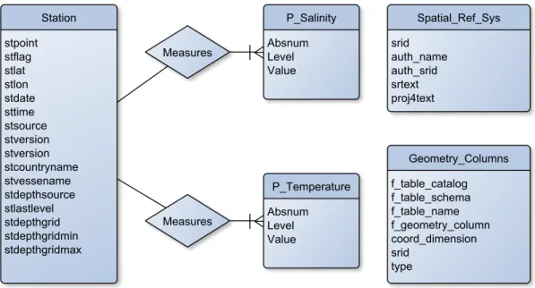
5 Data transformation 35 5.1 The ODB database . . . 35
5.1.1 ODB database diagram . . . 36
5.1.2 Development subset . . . 37
5.1.3 Towards Simple Feature Access-compliance . . . 37
5.2 Implementing the new database structure . . . 38
5.2.1 Step 1 – Creating the database and importing data in PostGIS . . 38
5.2.2 Step 2 – Creating and populating geometry columns . . . 39
5.2.3 Step 3 – Spatial reference system . . . 41
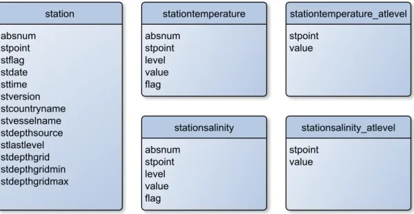
5.3 Resulting database structure . . . 41
6 Data accessor configuration 43 6.1 GeoServer overview and organisation . . . 43
6.1.1 GeoServer and PostGIS . . . 44
6.2 Offering geographic data through WMS and WFS . . . 44
6.3 Offering non–geographic data . . . 45
6.3.1 GeoServer SQL views . . . 46
6.4 Contour plots . . . 47
6.5 Exporting data . . . 48
6.6 The resulting “database” . . . 49
7 Client design and implementation 50 7.1 Development methodology and environment . . . 50
7.2 Front–end development challenges . . . 51
7.2.1 Browser compatibility . . . 51
7.2.2 Same Origin Policy . . . 52
7.3 JavaScript concepts, techniques and design patterns . . . 52
7.3.1 Namespace management . . . 52
7.3.2 TheModule and Revealing Module design patterns . . . 53
7.3.3 Module . . . 53
7.3.4 Revealing Module . . . 55
7.3.5 Module dependency management . . . 55
7.4 Client application design . . . 58
7.5 Client application architecture . . . 58
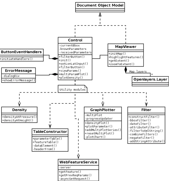
7.5.1 UML model . . . 59
7.5.2 Modules and relationships . . . 60
7.6 Control modules . . . 61 7.6.1 Control . . . 61 7.6.2 MapViewer . . . 62 7.6.3 ButtonEventHandlers . . . 64 7.6.4 ErrorMessage . . . 64 7.7 Utility Modules . . . 64 7.7.1 TableConstructor . . . 65 7.7.2 WebFeatureService . . . 65 7.7.3 GraphPlotter . . . 66 7.7.4 Filter . . . 66 7.7.5 Density . . . 68
7.8 Testing and quality assurance . . . 69
7.8.1 W3C standard compliance . . . 69
7.8.2 JavaScript best practices . . . 70
7.8.3 Unit testing . . . 70
8 System overview and demonstration 73 8.1 Searching in data . . . 74
8.2 Viewing parameter data . . . 76
8.2.1 Calculated data: calculation and presentation . . . 78
8.2.2 Viewing parameter data from several features . . . 78
8.3 Contour plots . . . 80
8.4 Exporting features and graph plots . . . 80
9 Evaluation 82 9.1 Sub–goals . . . 82
9.1.1 Research and determine appropriate standards and best practices . 82 9.1.2 Determine criteria for, and make selections to construct software stack . . . 83
9.1.3 Transform geographic data to standard–compliant encoding . . . . 84
9.1.4 Provide data through standardised access methods . . . 84
9.1.5 Develop client application . . . 84
9.1.6 Evaluate goal achievement . . . 85
9.2 Research questions . . . 86
9.3 Evaluation conclusion – overall goal . . . 87
10 Conclusion 88 10.1 Status summary . . . 88
10.2 Future work . . . 88
10.2.1 Geographic data store . . . 89
10.2.2 Geographic data accessor . . . 90
10.2.3 Geographic presentation service . . . 90
10.3 Conclusion . . . 91
A OGC standard examples 93 A.1 SFA methods . . . 93
A.1.1 Query methods . . . 93
A.1.2 Analysis methods . . . 94
A.2 GML example . . . 94
A.3 GeoJSON example . . . 95
A.4 Filter Encoding example . . . 97
A.5 SLD example . . . 98
B Barnes Surface Interpolation in GeoServer 100 B.1 Rendering transformation SLD file . . . 100
C WebFeatureService module 103 C.1 Description . . . 103
C.2 Source code annotations . . . 103
2.1 Conceptual model of the application . . . 9
3.1 Web Map Service – GetMap operation . . . 18
3.2 Conceptual model – OGC standards aware . . . 25
4.1 Conceptual model – technologies . . . 33
5.1 ER–diagram: the legacy database . . . 36
5.2 ER–diagram: The new database structure . . . 41
6.1 Configuring a layer in GeoServer . . . 45
6.2 ER diagram: OWS exposed layers . . . 49
7.1 Front–end application layout conceptual model . . . 57
7.2 Front–end application layout screenshot . . . 57
7.3 Front–end application UML class diagram . . . 59
7.4 QUnit test framework demonstration . . . 72
8.1 Initiating a search with the query GUI . . . 74
8.2 Sequence diagram: searching in data – request procedure . . . 75
8.3 Sequence diagram: searching in data – presentation procedure . . . 75
8.4 Search results in the GUI . . . 76
8.5 Sequence diagram: viewing parameter data . . . 77
8.6 Viewing parameter data . . . 77
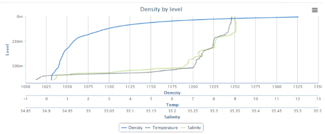
8.7 Viewing calculated density data in a graph plot . . . 78
8.8 Viewing parameter data from several features . . . 79
8.9 Graph plot interactivity . . . 79
8.10 Interpolated contour plot . . . 80
8.11 Exporting query results . . . 81
8.12 Exporting graph plots . . . 81
2.1 Front–end: Non–functional requirements . . . 10
2.2 Front–end: Functional requirements . . . 11
3.1 Well Known Text – example productions . . . 16
3.2 Web Map Service – common parameters . . . 19
3.3 Web Map Service – GetMap parameters . . . 20
3.4 Web Map Service – GetFeatureInfo parameters . . . 20
3.5 Web Feature Service – GetFeature parameters . . . 23
6.1 GeoServer WFS response formats . . . 48
3.1 URL for GetMap operation . . . 22
5.1 Creating the Station table . . . 38
5.2 PostgreSQL COPY function . . . 39
5.3 Adding a geometry column . . . 40
5.4 Transforminglat/lon pairs to geometry encoding . . . 40
6.1 GeoServer SQL View with parameter substitution . . . 46
6.2 GeoServer SQL View Regular Expression validation pattern . . . 47
7.1 Namespace management . . . 53
7.2 Module design pattern . . . 54
7.3 Revealing Module design pattern . . . 55
7.4 Module dependency management . . . 56
7.5 Control module: leveraging functional programming . . . 61
7.6 MapViewer module: declaring a layer . . . 63
7.7 MapViewer module: map–control interaction . . . 63
7.8 TableConstructor module: creating HTML table rows for features . . . . 65
7.9 GraphPlotter module: generating graph plot for with multiple series . . . 67
7.10 Filtermodule: combining filter objects . . . 67
7.11 Filtermodule: object to XML representation . . . 68
7.12 Density module: equation example . . . 69
7.13 Unit test: Filter Encoding generation . . . 71
A.1 SFA SQL Option: distance query . . . 93
A.2 SFA SQL Option: intersection query . . . 94
A.3 SFA SQL Option: area analysis query . . . 94
A.4 GML example: single feature . . . 95
A.5 GeoJSON example: single feature . . . 96
A.6 Filter Encoding example: bounding box and date filtering . . . 97
A.7 SLD example: red circle with black outline . . . 98
B.1 Barnes Surface Interpolation SLD . . . 100
AJAX Asynchronous JavaScript And XML GIS Geographic Information System
GML Geographic Markup Language
HTTP HyperText Transfer Protocol
ISO International Organization for Standardization
ODB Oceanographic DataBase
OGC Open Geospatial Consortium
OOP Object–Oriented Programming
OWS OGC Web Service
SFA Simple Feature Access SLD Styled Layer Descriptor SRS Spatial Reference System
WFS Web Feature Service
WKB Well–Known Binary
WKT Well–Known Text
WMS Web Map Service
XML eXtensible Markup Language
1
Introduction
1.1
Background
A Geographic Information System (GIS) is a software tool used for storing, viewing, manipulating and analysing geographic data. GIS software has been around almost as long as software itself, as they are useful in a wide variety of scientific, governmental and commercial fields [10].
GIS accessed over the World Wide Web (WWW) are called Web–GIS. Web–GIS are
easily accessible for thin clients, reducing the client–side demands on storage size and computational power. However, additional development challenges for web applications, such as security and compatibility, also apply.
Many GIS software tools and suites exist, some customised for a data set or domain, others more generic. To aid integration and collaboration, standardisation of storage encodings, communication protocols, etc. is needed. This is perhaps especially important to Web–GIS as a part of the WWW, where a historical lack of standards and compliance has injured both developers and users [11]. The main standardisation body in the GIS domain today is the Open Geospatial Consortium (OGC) [12].
1.2
Motivation
A GIS named Oceanographic DataBase (ODB) is in use at NERSC to aid in research on marine climate in the Arctic ocean. ODB is built specifically for a fixed set of data, with a GUI providing querying, presentation and analysis tools. The data is structured around measurements of values such as temperature and salinity with both spatial and temporal variables.
This system has unfortunately aged to the point where it is cumbersome to use. Espe-cially detrimental is the overall software architecture: ODB is a single–client application, meaning data and processing power must be provided locally. Another central issue is the custom–built approach of ODB. Its underlying geographic data is not accessible by other tools, due to non–standard encoding and access methods. There are also additional miscellaneous shortcomings, including cumbersome navigation and the lack of a data export functionality.
An alternative solution is desired, following modern standards and best practices for geographic data encoding and publishing software architecture. A new system should provide the same basic functionality on the same set of data, while remedying the identified issues with the ODB system. It should also be open to extensions, including the addition of data from new sources.
1.3
Goals
The overall goal of this thesis is the construction of a prototype Web–GIS system as outlined in the previous section: a replacement for ODB. The constructed software system should store and provide access to the data contained by ODB using standardised formats and methods. The system should also have a front–end client that offers the same basic functionality as ODB does for query and analysis of the data, along with some additional, requested functionality. This client should be designed for extensibility and maintainability, and be available to use through internet browsers.
The entire system should be constructed from Open Source Software (OSS) and be modular to the point that any component may be independently improved on or replaced. More specific requirements for the system have been set before and during work on the thesis, and are the topic of chapter 2.
1.3.1 Sub–goals
To achieve the overall goal, a set of sub–goals has been identified. There are interdepen-dencies among the sub–goals, goal 1 is for example a prerequisite for completing goals 2, 3 and 4, but the goals were generally worked on in parallel through an iterative process. All sub–goals are presented in more detail in chapter 2. The sub–goals are as follows:
1. Research and determine appropriate standards and best practices 2. Determine criteria for, and make selections to construct software stack
3. Transform geographic data to standard–compliant encoding 4. Provide data through standardised access methods
5. Develop client application 6. Evaluate goal achievement
1.4
Research questions
Some research questions guide the thesis:
• Is it possible to construct a modern and standard compliant replacement for ODB using open source tools and software?
• What are the current relevant standards in constructing marine web–GIS software?
• What challenges are associated with modernising GIS systems such as ODB to be web–based and standard compliant, and how may these challenges be approached?
As with goals and requirements, we elaborate on these questions in chapter 2.
1.5
Thesis structure and outline
With our background and goals presented, we now introduce the remaining thesis text. The text is split into four parts:
• Part 1 (chapters 1 and 2) forms the introduction and problem statement.
• Part 2 (chapters 3 and 4) introduces and outlines relevant concepts and technologies. This part corresponds to sub–goal 1 and 2.
• Part 3 (chapters 5, 6, 7) covers software design and implementation – the solution to our defined problem. This part corresponds to sub–goals 3, 4 and 5.
• Part 4 (chapter 8, 9 and 10) concludes the text by giving an overview of the constructed software system and evaluating the result and work process. This part covers sub–goal 6.
Chapter 1: Introduction
Presents the background and motivation for the thesis. The goals to achieve and research questions to answer are introduced. An outline for and overview of the thesis is provided.
Chapter 2: Problem statement
Refines and details the goals, challenges and scope of the thesis. The software development aspect is introduced with a conceptual model of the system to be constructed, along with a requirements analysis section.
Chapter 3: Geospatial concepts and standards
Gives an introduction to relevant concepts and standards. Simple Feature Access, Web Map Service and Web Feature Service are presented in detail, and other standards are introduced more briefly.
Chapter 4: Software stack
With a software stack and its communication protocols and roles outlined in the previous two chapters, a set of software technologies to fulfil these roles are selected. Alternatives are presented and evaluated from a set of criteria that are also determined in the chapter.
Chapter 5: Data transformation
The steps required to transform the data from the ODB application to a standard complaint structure are defined. An implementation of these steps is then presented.
Chapter 6: Data accessor configuration
The data accessor component of the software stack is configured to publish our data according to web standards.
Chapter 7: Client design and implementation
A description of the structure and implementation of the user client in our system. Begins with a description of used design pattern, and then presents each code component of the application.
Chapter 8: System overview and demonstration
A guided tour through a selection of use cases. This chapter serves both as a demonstration of the full system and a full explanation of how the components configured/designed in the three previous chapters interact.
Chapter 9: Evaluation
The achievement of goals, requirements and the work process is evaluated. The chapter also gives a basis for determining future work.
Chapter 10: Conclusion
This chapter concludes the thesis by summarising the state of the system, outlining possible future work and giving an account of the work an learning process.
Three appendices are also included:
Appendix A: OGC standard examples
Demonstration of SFA methods and example files for various OGC stan-dards.
Appendix B: Barnes Surface Interpolation SLD
A complete GeoServer SLD rendering transformation file.
Appendix C: WebFeatureService module
Provides the full source code for a module from the client application along with detailed annotations.
2
Problem statement
This chapter provides more details on the goals, research questions and scope of the thesis. The requirements for the system to be constructed are also presented. A conceptual model of the system described in the overall goal is designed and presented. This model will be built on in Chapter 3 and 4.
2.1
Elaboration on goals
We go into more detail on the sub–goals listed in section 1.3.1.
1. Research and determine appropriate standards and best practices In replacing the ODB application, we must take special care in not constructing a system that will soon suffer the same fate as ODB did. All data encoding and communication should be performed according to the current standards and best practices in the field of web–GIS. Developing according to this goal requires research into what exactly these standards and practices are.
2. Determine criteria for, and make selections to construct software stack The new system should not be a monolithic piece of software, but rather a collection of modular components with well–defined roles. It is not our intention to develop all these components ourselves, but to employ available software tools and technologies. Many valid options exist, so we must determine a set of criteria on which to judge and select components. A selection of software must be made according to these criteria. The roles and requirements of each component are discussed in section 2.3. For roles where there is no available software to fulfil the requirements, new software must be developed. This is the case for the front–end user client of our system. The
development of this client is covered by sub–goal 5. Principles of modularity and extensibility are just as important for this component as for the others.
3. Transform geographic data to standard–compliant encoding
With the desired data encoding established through achieving sub–goal 1, we must transform the data from ODB into this encoding. The ODB database may be referred to as thelegacy database and its data may be referred to asthe legacy data. The transformation process involves getting an understanding of the initial state of the data set and tools by which to transform it. We will refer to the resulting software component that holds these data as ageographic data store.
4. Provide data through standardised access methods
We must avoid having the data “locked” to our system by utilising loose coupling between components; storage and presentation must be separated. The data will then be available not only to a specific presentation application, but any client that adheres to employed protocols. Achieving this separation requires that all access of data is handled through standardised methods. We will refer to the component that accesses the data store and publishes the data through standardised interfaces as thegeographic data accessor.
5. Develop client application
The two previous sub–goals outline a software stack, where the components dis-cussed form the lower layers related to data and data access. In constructing an ODB replacement, an user client with a GUI must also be developed. The re-quirements for this component are covered in section 2.3, in more detail than for the components of sub–goal 2. This component is referred to as the geographic presentation service,front–end application or simply the client application.
6. Evaluate goal achievement
When all preceding goals are complete, the achievement of each should be assessed. In this process, lessons learned and conclusions can be extracted.
2.2
Research questions
Along with goal statements, some research questions guide the thesis. These questions are to serve as a companion to the more pragmatic sub–goals identified in the previous section. While no part of the thesis text directly target these questions until the evaluation chapter, answers are expected to be produced by completing the sub–goals outlined in the previous section.
The central question is whether or not it is feasible to construct a system as outlined by the goals with our requirements and restrictions (more on this in the next section):
• Is it possible to construct a modern and standard compliant replacement for ODB using open source tools and software?
The requirement on standard compliance generates another question:
• What are the current relevant standards in constructing web–GIS software?
The work process should also produce some more general knowledge that may be useful in similar undertakings:
• What challenges are associated with modernising GIS systems to be web–based and standard compliant, and how may these challenges be approached?
2.3
System architecture and requirements
Sub–goals 3, 4 and 5 set the stage a software development process required to achieve the overall goal. In Figure 2.1, the goals are represented in a conceptual model of a software system. This is also a model of the system as imagined from the overall goal. In the remainder of the text, this model will be referred to asthe conceptual model.
We now look at the three components in this conceptual model and identify some re-quirements for each component. The rere-quirements identified here are broad and generic. During Chapter 3, we examine current geographic data encoding and communication standards to refine these requirements.
Standard compliance is the central requirement for all components. We also wish to employ open source software and tools when feasible. We will not list this a requirement here – it is introduced properly in Section 4.1.
The three components presented below are all found in Figure 2.1. As can be seen in this model, they form a hierarchy where the data presentation service depends on a data accessor, which in turn depends on a data store. These components, with these dependencies, form a layered system that will be referred to in the thesis as oursoftware stack.
F i g u r e 2 . 1 : Conceptual model of the application
2.3.1 Geographic data store requirements
The geographic data store corresponds to sub–goal 3. Successfully transforming the legacy data should result in it being available for query in a standard compliant data store, for example a database. The general requirements are:
• Quality and efficiency in common data store operations
• Compliant with relevant standards in geographic data encoding
• Support for reading text files for loading the legacy data set
2.3.2 Geographic data accessor requirements
The geographic data accessor corresponds to sub–goal 4. It should allow access to the data store through web services. It is not necessarily a single “physical” component – several pieces of software may be required if we need support for several protocols. The requirements are:
ID Description
NFR1 Accessible and responsive user interface NFR2 Quick response time for simple operations
NFR3 Information on status during more complex operations
Ta b l e 2 . 1 : Front–end: Non–functional requirements
• Provides standardised access methods for the underlying data store
• Configurable for adapting to our data set
• Adequate performance – tasks may be computationally demanding
Exactly what level of performance is adequate is hard to determine, as tasks performed on large amounts of data are expected to be computationally demanding.
2.3.3 Geographic presentation service requirements
This component corresponds to sub–goal 5. Its goals are to allow navigation in and analysis of our data set by communicating with the geographic data accessor. Architec-turally, it will exist in a web application context, so it should be accessible by a regular web browser. Functional requirements are guided by the existing ODB application and especially noted shortcomings in that application.
In contrast to the other components, where we employ ready–made software that fulfil our requirements, this components was developed as part of the thesis. Development was based on a set of non–functional and functional requirements. The requirements evolved throughout the development period, with the current sets presented here. The initial set was smaller, with new functional requirements added as others were implemented. More on development methodology in Section 7.1.
Table 2.1 lists non–functional requirements by an identifier and a description. Table 2.2 lists the functional requirements. Some of the terms used here, such as feature will be clarified in Chapter 3. Read requirements as “The application must provide < descrip-tion>”.
The achievement of the requirements will be evaluated (as part of sub–goal 6) based on what functionality is present in the final system and the correctness and completeness of the implementations.
ID Description
FR1 Query of data based on various parameters (bounding box, time, at-tribute values)
FR2 Presentation of features and parameters in tabular form FR3 Presentation of parameter values as graph plots
FR4 Map widget with functionality (pan, zoom, layer selection)
FR5 Map widget/query interactivity: search based on selected area of map FR6 Graph plot presentation of a parameter value for multiple features FR7 Calculation and presentation (table, graph plot) of density based on
parameters
FR8 Interpolation and display of contour plots based on parameter values FR9 Export functionality for all tables and graph plots
Ta b l e 2 . 2 : Front–end: Functional requirements
2.3.4 Scope of functionality
As stated in the overall goal, a prototype for a full replacement for the ODB system is to be constructed. The ODB system has a substantial set of functionality, so a full re–implementation is beyond the time frame designated for this thesis. The constructed software stack and client application will serve as a base on which to further develop the system, suited for further implementation of functionality from the ODB system or completely new functionality. Care must be taken not to make design or implementation decisions that would hinder such future developmental work.
Notable features present in ODB that are not implemented in this prototype include:
• Altering data
The features identified in the functional requirements require read–only access to the data. Altering the data is especially challenging in the web domain where multiple users may access the same data at the same time. This challenge is not present in ODB, where data is stored locally. Data storage, access and client design must accommodate for the addition of read–write functionality.
• Misc. plots and query tools
A basic, representative set of query tools and plots are to be implemented. The infrastructure developed for these features must accommodate for extensions. The functional requirements reflect this, with an attempt made to select diverse func-tionality rather that focusing on the detail of a single feature.
3
Geospatial concepts and standards
In this chapter, we introduce standards that are central to the construction of our system. Along with the standards, important concepts are also defined and introduced.
We begin with a brief introduction to the OGC and its role in GIS standardisation. Next, we present a selection of standards and concepts that are very relevant to the remaining thesis. Simple Feature Access (SFA) is introduced first, a specification for geographic data stores. We then discuss two important OGC web services (OWS); Web Map Service (WMS) and Web Feature Service (WFS). We also briefly present some other OGC standards that are less important, but still relevant to this thesis. With knowledge of these standards, we update the conceptual model of our system to reflect which standards will be employed.
3.1
The Open Geospatial Consortium
The Open Geospatial Consortium (OGC) maintains a large number of open standards that are central to geospatial software development and research. These standards define interfaces and encodings for the storage and exchange of geospatial data. The OGC was founded in 1994 with a board of 8 members from governmental bodies, academia and private corporations. It has since grown to include (as of writing) 482 members.
The OGC standards cover a large range of topics - some general in concept and others focused towards specific domains or situations. For example, the Geographic Markup Language (GML) defines a data encoding scheme for describing geographic objects in general. CityGML, on the other hand, is a data encoding scheme specifically for describing three dimensional models of cities (with buildings). Some OGC standards are also International Organisation for Standardisation (ISO) standards.
3.1.1 OGC standard compliance
The expression ”conforming to standards” (frequently used in previous chapters) in the GIS domain largely means to conform to appropriate OGC standards. The OGC distinguishes between implementing andcertified compliant software technologies. The first category uses an OGC standard by fully or partly implementing it. The second category is much stricter and requires that the software be put through a rigorous testing process [13] to qualify.
Our application does not aim to implement any specific standard, but use software that is compliant and conform to any relevant encoding schemes and communication protocols. When choosing software to fulfil technological needs, it should however be considered a major bonus if it is certified compliant with relevant OGC standards. This ensures both the correctness and completeness in implementing the standard, as well as being a general sign of quality for the software product.
3.2
Simple Feature Access
TheSimple Feature Access (SFA) standard (full name:Geographic information – Simple feature access) is a specification for the storage and manipulation of geographic data. It consists of two parts: part 1, known as ”Common architecture” [14] and part 2, ”SQL Option” [15]. It is also an ISO standard [16, 17].
This section will largely be a synopsis of these standard parts in their current version, with an emphasis on the topics most relevant to this thesis. Technical discussions will be shortened and simplified (for the sake of brevity), and parts considered irrelevant or unimportant to this thesis will be omitted entirely.
3.2.1 Part 1 – Common Architecture
The Common architecture standard defines a set of data types, storage formats and operations for simple features. A feature is conceptually defined by the standard as “an abstraction of a real world phenomenon”. In practical use,simple features can be understood as features with associated geometry (such as a measurement of temperature (a feature) on a specific longitude/latitude 2–D point, on a line of such points, or on a polygon constructed from such points (all examples ofsimple geometry)). The standard also gives a more rigorous definition. We will look at how simple features are constructed, what actions may be performed on them and how they are represented. The standard
uses technical terms (such asclass, abstract class, method) from the Universal Modelling Language [18][19] that will be reused here.
3.2.1.1 Geometry and the class hierarchy
The abstract (non–instantiable) class Geometry serves as the base class for all simple feature geometry. All simple features are instances of subclasses ofGeometry. All instances must have an associatedspatial reference system (SRS). A SRS describes the coordinate system in which a geometric object is placed. By enforcing that everyGeometryinstance’s coordinates are described in a SRS, all instances are commensurable by translation to a common SRS. The standard defines a set of methods for the Geometryclass. These are split into three categories:
• Basic methods
Basic methods describe the geometric object represented, giving its dimension, geometry type, SRS, etc. Here are also some “utility”–methods such asAsText() andAsBinary(), returning a representation of the geometric object inWell Known
Text (WKT) or Well Known Binary (WKB), respectively. WKT and WKB are
the topic of section 3.2.1.3. Common to all basic methods is that they take no parameters and are generally retrieval of data rather than computation–focused. Basic methods are essential building blocks for methods in the remaining categories.
• Query methods
Query methods focus on the geometric object’s relation to other geometry. These methods all take one parameter; an instance of theGeometryclass. There are query methods for testing equality (spatial equality – not object equality), intersection, touching, containing, overlapping, etc. The behaviour of these methods varies with the type of the Geometryinstances involved.
We will require query methods when building our prototype, for example to filter out measurements made within a specificbounding box. Such functionality requires being able to determine the set of pointthat are within a box–polygon. The use of some query methods is demonstrated in Section A.1.1.
• Analysis methods
Analysis methods depend upon the accuracy of the SRSs involved. As with query methods, these method operate on two instances of geometry. Methods include measuring the least distance between any two points in two geometric objects, generating the convex hull of an object, generating the union/difference between two objects, etc. The use of an analysis method is demonstrated in Section A.1.2.
It is the responsibility of the implementer to represent all subclasses of the Geometry class and provide these methods for them. Geometry also has a “companion” abstract subclass inGeometryCollection. This is an abstract class for representing a collection of Geometry (subclass) instances. There are no constraints on this abstract collection except that all instances it contains must have the same SRS.
3.2.1.2 Geometry subclasses
Four classes directly subclass the Geometry class (including the previously discussed GeometryCollectionclass). Several of the subclasses have subclasses of their own. The GeometryCollectionclass notably has a subclass for almost all other instantiable classes – representing a collection of objects from these classes (named Multi-..., for example
MultiPoint).
We will now list and present briefly the other subclasses of Geometry. In addition to their inherited methods (these will not be repeated in the list), subclasses may provide additional methods. Some of these are found only in certain classes. TheLine class, for example, has the basic methodlength(), which would not make sense for aPointobject which by definition has no length.
• Point
The Point class represents the simplest geometric object in the Simple Feature Access standard. It consists of an x and y coordinate. It may have up to two additional coordinates if that is required by its associated SRS. It has no methods beyond those inherited from theGeometryclass. APointis well suited to represent an instance of two dimensional coordinates such as latitude/longitude pairs.
• Curve
The Curve class is an abstract class representing curves by being a collection of points with an interpolation algorithm. The Curve class provides methods for measuring length, retrieving start– and end–points and checking whether the curve is closed or if it is a ring.
• Lines (LineString, Line)
The LineString class subclasses Curve, and specifies linear interpolation for its points.Line is a special case ofLineString: it has only two points. There is one additional line geometric object – the LinearRing, which is a LineString with special properties. We will not discuss it further. Lines are suited to represent relationships between points.
Description WKT representation A Pointat(5, 10) Point ( 5 10 ) A 3D Pointat(5, 10, 7) Point Z ( 5 10 7 )
A LineStringof three points LineString ( 5 10, 7 14, 2 10 )
A simple Polygon Polygon (( 5 5, 5 10, 10 10, 10 7, 5 5 ))
Ta b l e 3 . 1 : Well Known Text – example productions
• Surfaces and polygons
There are four additional classes that represent geometric objects that are not immediately relevant to the work in this thesis, so they will only be mentioned. These are the surface classes Surface andPolyhedralSurface and the polygon classes Polygon and Triangle. Polygons are well suited to represent geographic areas such as a seas or national borders.
3.2.1.3 Well Known Text and Well Known Binary
The SFA standard defines two data storage formats:Well Known Text (WKT) and Well Known Binary (WKB). As the names imply, the formats store and present Geometry instances in a textual and a binary representation, respectively.
WKT is defined rigorously with a grammar in Backus–Naur Form that will not be reproduced here. Some example productions are given in Table 3.1. Note again that the given coordinates hold no meaning relative to anything but themselves without an associated spatial reference system: the geographic features in the table can not be compared meaningfully to each other without knowledge of their SRS.
WKB is not human–readable, and its details are beyond the scope of this text. Since the Geometryclass has the basic method AsText(), a human–readable representation will always be available to the user of a SFA compliant system.
The standard also defines a WKT representation of SRSs with a BNF grammar. In this thesis text, the terms Well Known Text and WKT will always refer to the encoding of geometry that has been the topic of this section, not that of SRSs.
3.2.2 Part 2 – SQL Option
The SQL Option part of the Simple Feature Access standard [15] is a standard for and guide to implementing the Common Architecture in SQL. There exists equivalent
documents for OLE/COM [20] and CORBA [21] technologies as well. However, these stan-dards and/or technologies have fallen into disuse (the latest versions of these documents are over 10 years old), so they will not be covered in this thesis.
The standard provides implementation restrictions and advice for representing all the ge-ometry types found in the Common Architecture (the classes described in Section 3.2.1.1 and 3.2.1.2) using only standard SQL data types. This comprises a significant part of the standard text. However, it also acknowledges the usage of SQL User Defined Types (UDT) as a valid alternative. We will not repeat the at times complex operations described for using only built–in SQL data types.
The SQL Option standard defines two meta–data tables called SPATIAL REF SYS and GEOMETRY COLUMNSthat must be present in a compliant database. TheSPATIAL REF SYS table should contain all SRS used by the system, encoded in SRS Well Known Text format (discussed in the last paragraph of 3.2.1.3). GEOMETRY COLUMNSis a catalogue of all columns of a Geometrydata type in the database.
3.3
OGC web services (OWS)
The OGC maintains several web service standards, commonly named with a Web prefix and categorized as OGC Web Services (OWS). They define communication protocols for GIS operations, such as requesting information on a specific feature or requesting an image of a map with certain parameters. All these protocols are constructed as standard HTTP request/responses using various HTTP methods. These protocols allow easy construction and interconnection of GIS web applications.
As HTTP communication protocols, a clearclient/server divide is present in all services. A server that implements a service accepts and responds to valid requests from a compliant client. Two–ways communication is of course also possible if both parts can act as both server and client. The role of both server and client will be discussed when we look closer at the specific services.
3.4
Web Map Service
TheWeb Map Service (WMS) standard is defined in [22]. The standard is supplemented with a number of best practices documents [23, 24] and discussion papers [25–27]. A server that implements the WMS standard will, upon request, serve images generated from some underlying geographic data. We will refer to such a server simply as offering
F i g u r e 3 . 1 : Web Map Service – GetMap operation
and being aWeb Map Service (WMS). Figure 3.1 is a conceptual model of a successful WMSGetMapoperation – a practical example and description is provided in section 3.4.2. Standard compliance will guarantee the possibility of a client combining multiple gener-ated images from several WMSs (either from different physical servers, or from different WMS’ hosted on a single server) onto a single surface. This enables, for example, build-ing a web application that displays temperature measurements on top of a variety of underlying map images such as satellite photos, coastline bathymetry, etc.. Since the images from a WMS server are generated dynamically, rather than simply selected from a predetermined set, the application could also support multiple zoom levels with varying amounts of geographic details in the map.
3.4.1 The WMS operations
The WMS standard defines three operations:GetCapabilities,GetMapandGetFeatureInfo (which is optional to implement) . Implementers may also define additional non–standard
operations. We will look briefly at each one (from the standard) in this section, while section 3.4.2 re–examines the centralGetMapoperation in more detail.
The operations are carried out as HTTP requests towards the WMS. Both GET and POST–methods are described in the standard, but supporting POST is optional. Using GET, parameters are set in the URL, while using POST the parameters are set and sent to the server in a simple XML–file. There is a fixed set of required parameters for each
Parameter Description
service Service the request is for
version Version of WMS the request is for request Which operation the request contains
Ta b l e 3 . 2 : Web Map Service – common parameters
operation, and additional optional parameters for some. A parameter being mandatory means both that the client must supply it in a request, and that a server must be able to handle any functionality it implies.
We will now look at the operations; outlining their purpose and selected parameters. Example code for performing a complete operation (as illustrated in figure 3.1) is found in the next section. Operations marked optional are not required to be supported by implementations.
Note that we will not discuss technical complexities present in the standard such as the valid representation of numerical values in requests, coordinate systems (except briefly for relevant operations), etc.
• Common parameters for all operations
Table 3.2 presents the parameters that should be in included in all operation– requests (all but versionare mandatory). Theserviceparameter must be set to “wms”, indicating to the receiving server that the HTTP request is a WMS operation.
version should reflect that of the WMS the request is targeted to (or, if the WMS supports several, the version the request itself should be identified as).request is set to reflect the type of operation that follows, being the name of the operation (as they are named in this list).
• GetCapabilities
GetCapabilities is the simplest WMS operation; it has no additional mandatory parameters beyond the standard set. The WMS server will respond with valuable metadata – a list of its “capabilities”. Capabilities include information on the WMS
service itself (service name, contact information, etc.), what WMS operations it provides and information on available geographic data.
Optional parameters includeformat, which specifies which data format (in MIME– type) the capability–response should be served as. The standard defines quite extensively the contents and phrasing of the response.
Parameter Description
layers List (comma–separated) of map layers styles List (comma–separated) of styles
SRS Spatial reference system
BBOX Bounding box coordinates
width Pixel width of the map image height Pixel height of the map image format Output format of the map image
Ta b l e 3 . 3 : Web Map Service – GetMap parameters
Parameter Description
layers List (comma–separated) of map layers info format Format of feature info
i i pixel coordinate of the feature
j j pixel coordinate of the feature
Ta b l e 3 . 4 : Web Map Service – GetFeatureInfo parameters
Table 3.3 lists the mandatory parameters of the GetMap operation. This is the operation that actually produces a map image, as visualized in figure 3.1, and is as such the most important operation of a WMS. We will look at a practical example of this operation in section 3.4.2.
layersis a list of layers from which the image should be produced. The names of the available layers in a WMS is retrieved throughGetCapabilities. Thestyles parameter is a list of styles to be applied on geometry when rendering the layers of the map image. It must correspond 1–to–1 with the layers list. SRS (map projection) andBBOX define a bounding box on the layers in which the geometry is rendered out to the map image.BBOX syntax is min x,min y,max x,max y. The SRS applies to the bounding box itself, and is necessary to give meaning to the coordinates specified for the bounding box. width,height and formatapply to the produced map image itself, giving its desired width, height and output format. Supported output formats for each available layer is given in aGetCapabilities response.
Optional parameters include the option of producing images with transparent back-grounds (necessary for overlaying several map images) or setting the background to a specific colour.
• GetFeatureInfo (optional)
The optionalGetFeatureInfo operation allows clients to query the WMS on more information regarding features that it has discovered through aGetMapoperation. The use case outlined in the standard is a user using a WMS client to click on an area
of a retrieved map image, whereupon a GetFeatureInfo operation is performed with the appropriate i and j parameters. The client may then present the user with more information on the specific feature. The content and formatting of this information is left to implementers.
A WMS announces its support for the GetFeatureInfooperation by setting the queryable option for a layer when listing them in aGetCapabilities operation. A successfulGetFeatureInforequest requires support for the operation both from the WMS itself and for the layer that is queried. Optional parameters include setting the (maximum) amount of features to be listed for the chosen pixel coordinates (the graphical representation of features are likely to overlap at some zoom levels).
GetFeatureInfois interesting because it shares usage scenarios with Web Feature Service, which is the topic of section 3.5. WFS offers wider and more complex functionality, so using GetFeatureInfo is not necessary if there is also a WFS serving the same geographic data. It is, however, a neat alternative if WFS is not available.
3.4.2 The GetMap operation in practice
In this demonstration, we assume a WMS is hosted onhttp://demonstration.web.com/wms. Through a GetCapabilitiesrequest, we already know of the layer measurementsand that the WMS supports outputting in the PNG image format. We now want to retrieve an image of the layer with the following parameters:
• Bound by the box given by coordinates-120.0, 18.2, -37.0, 42.3 (box defined by lower left corner point at (-120.0, 18.2) and upper right corner point (-37.0, 42.3)) in the spatial reference system ESPG:4326 (the details of this SRS is not important at the time, but required to give meaning to the box coordinates)
• Default styling
• Image width of 700 pixels
• Image height of 300 pixels
• Image format PNG (MIME–typeimage/png)
A WMS must support operations over HTTP GET. In the GET–method, parameters are added to the URL as key–value pairs with “=” indicating assignment and using “&” as a delimiter. The parameter list is appended (with a leading “?”) to the URL of the host which will receive the request.
1 h t t p :// d e m o n s t r a t i o n . web / wms ? 2 r e q u e s t= G e t M a p 3 &s e r v i c e= wms 4 &v e r s i o n= 1 . 1 . 1 5 &l a y e r s= m e a s u r e m e n t s 6 &s t y l e s= 7 &srs= E P S G %3 A 4 3 2 6 8 &b b o x= -120.0 ,18.2 , -37.0 ,42.3 9 &w i d t h= 700 10 &h e i g h t= 300 11 &f o r m a t= i m a g e %2 F p n g
C o d e L i s t i n g 3 . 1 : URL for GetMap operation
The URL for HTTP GET–request with our specified parameters is given in code listing 3.1. Note the percent–encoding [28] of some characters and the splitting of the URL into several lines for readability. The styles parameter is empty, meaning it will be filled with the WMS server’s default value. Styling is discussed further in section 3.6.2. The request can be made with any client supporting HTTP GET request (for example by navigating to the URL in an internet browser). Making the request corresponds to step 1 of figure 3.1. The response will include a map image constructed to our parameters. Generating this image corresponds to step 2 of the figure, while step 3 would be the client receiving the image as a response. How step 2 is performed is not described by the standard, leaving this process to the server implementers.
If the WMS supports performing operations through HTTP POST, the same result could be achieved by setting the same parameters in an XML file included as the message of the POST–request. A schema for such XML files are defined in the WMS standard.
3.5
Web Feature Service
The Web Feature Service (WFS) standard defines a protocol for exchanging geographic information over HTTP. While WMS generates and transmits images, WFS transfers information on features encoded in the Geographic Markup Language (GML). GML is an XML–based markup language that is its own OGC standard and is presented briefly in section 3.6.1.
The WFS standard is defined in [29] and [30], along with a discussion paper [31] and a best practices document [32]. The latest version of the standard is [29], which is also an ISO standard as [33].
Parameter Description
typeName The WFS equivalent of WMS’layers; the container for which the request is intended
featureID Supply an ID as this parameter to retrieve this specific feature maxFeatures The maximal number of desired features in the response propertyName Retrieve only the desired property from a feature. May also
retrieve several by providing a comma–separated list. Equiva-lent to retrieving a subset of a row instead of the entire row from a database.
filter Provide a Filter Encoding (see 3.6.3) encoded filter that re-stricts the returned set of features
Ta b l e 3 . 5 : Web Feature Service – GetFeature parameters
WFS is built to support transactions to enable users simultaneously accessing the service (then sometimes called WFS transactional (WFS–T)). This adds a general layer of complexity, along with several operations. Editing the data is not currently a functional requirement of our system, so these capabilities will not be discussed here.
3.5.1 WFS Operations
The WFS protocol itself is structured similarly to WMS. For this reason, we will not repeat theweb protocol aspects shared between WMS and WFS. Instead we go directly to the operations relevant in constructing our system.
• GetCapabilities
This operation is equivalent to the GetCapabilitiesoperation of WMS. It serves the same purpose and is structured similarly.
• GetFeature
TheGetFeatureoperation is WFS’ central operation: it produces a feature or set of features according to the input parameters. An interesting set of parameters is pre-sented in Table 3.5, note that familiar, mandatory parameters (service, version, requestetc.) are omitted. The default response format for theGetFeature opera-tion is GML; see Secopera-tion 3.6.1 for an introducopera-tion to the format and Secopera-tion A.2 for an example.
3.6
Other relevant standards
The standards presented below all see use in the constructed software, but are not essential aside from when discussing implementation details (the topic of Chapter 7). Their presentation here will be very brief, and does not reflect their general size or importance (GML, especially, is a very substantial and fundamental standard).
3.6.1 Geography Markup Language and GeoJSON
Geography Markup Language (GML) is an XML–based encoding for geographic features. It is the default encoding used for OWSs such as WFS. GML documents may be validated against the official GML schemas hosted by the OGC. The GML standard is defined in several documents corresponding to versions, the latest being [34], along with several discussion papers and best practice documents.
GML is in use in our prototype application. We have however opted to use GeoJSON [35] as the standard internal encoding in the client application. GeoJSON is equivalent to GML in purpose, but is encoded in the JSON format [36]. An example GML file is provided in Section A.2, and a GeoJSON encoding of the same feature is provided in Section A.3.
3.6.2 Styled Layer Descriptor
Styled Layer Descriptor is an OGC standard that enhances WMS with additional options for customising the style (presentation) of layers served from a WMS. Styles are defined in XML markup that follow a schema set by the standard. The standard is defined in [37, 38].
Styles are used to alter the look of features as they appear from a WMS request. For example, the feature representation could change colour based on the value of some attribute it contains. The WMS must provide a default style, requested by supplying an empty STYLEparameter in a WMS URL, but can also be provided by the client using this parameter. An example SLD file is provided in Section A.5.
3.6.3 Filter encoding
The OGC filter encoding is an application–neutral XML encoding forfiltering of features. A valid OGC filter can be supplied in a WFS request as the FILTERparameter, replacing
F i g u r e 3 . 2 : Conceptual model – OGC standards aware
theBBOXparameter (the two are mutually exclusive due to functional overlap). Filtering results on WFS–server side is beneficial as it lessens the network load and client workload. A filter may contain various rules, such as “attribute temperature must be between 10 and 20”, that can be combined or altered by the logical operators AND, OR andNOT. Filtering may also be performed on geographic attributes, so filtering can fully replace the simpler BBOXparameter in WFS.
An example Filter Encoding file is provided in Section A.4.
3.7
Conceptual overview model with appropriate standards
Figure 3.2 is the conceptual model of the system to be constructed, now updated to indicate which standards will be used.
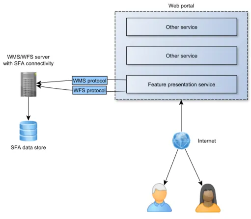
It is clear that the geographic data store must be SFA compliant, and will probably be a technology implementing the SQL option. The geographic data accessor must function as an SFA–aware client towards the data store, using the methods the SFA standard defines to present the geographic data. It will present this data to clients (thus functioning also as
a server) by being a Web Map– and Web Feature Service (they may be hosted on separate servers, but are represented as one entity in the model). In short, this component will be – as we imagined – an intermediate “translator” of client requests to spatial database queries; its languages will be SFA methods and WMS/WFS operations.
The presentation service, accessible to regular users over the internet, will use the WFS and WMS protocols to communicate with clients. The primary data encoding of WFS traffic will be GeoJSON, but other formats (including GML) are still relevant due to FR9 (data export). In this model we have renamed the service itself to “feature presentation service” to align ourselves with the terms of SFA. We will still refer to this component as the (front–end) client application or geographic data presentation service elsewhere.
4
Software stack
The software components and relationships between them used in constructing a layer– structured application is referred to as asoftware stack. In the previous chapters, such a stack was conceptually outlined in a series of models. In this chapter, we again update this model by selecting implementing technologies for all entities in the conceptual model. The result is a complete, real software stack on which the application will be developed. We begin by discussing and determining a set of criteria on which to evaluate soft-ware technologies. With these criteria in mind, the selection processes are presented in a bottom–to–top order (beginning with the data store). The chosen technology is introduced in some detail, and relevant concepts may also be discussed.
4.1
Selection criteria
The problem statement guides the criteria on which potential software technologies are evaluated. Four main criteria are presented below, in a partially prioritised list (the first criterion being the most important).
• Potential in fulfilling requirements
Requirements for each component was detailed in chapter 2. Any selected software must be able to fulfil their appropriate requirements.
• Standard compliance
As described in Chapter 2, we aim to achieve maintainability and extensibility by utilising standardised data encoding and communication. This makes the stan-dard compliance of involved software technologies a very important criterion. The standards to implement or support were introduced in Chapter 3 and summarised
in Section 3.7. Cerified compliance (see Section 3.1.1) is valued over claimed or incomplete support.
• Open source
It is part of the overall goal of this thesis that all software involved should be open source. The most important benefits of choosing open source software over proprietary solutions are reported to be avoiding vendor lock–in, cost and quality [39]. Avoiding lock–in is especially important to this software system to maintain modularity of components beyond just the initial deployment.
An open source software alternative will be valued over any proprietary software unless it lacks in other criteria. We will not pay much attention to the complexities ofopen sourceversusfree licences [40], concluding simply that “open source” status is sufficient for our needs.
• Perceived quality
Software quality is hard to define or measure. Our selection will be based on the perceived quality of a software technology – developing with all alternatives and evaluating the result would be too time–consuming. Quality indicators are widespread use, quality and availability of documentation, test coverage, standard compliance, etc.
• Future support
As with quality, evaluating how well a software technology will be supported after initial deployment is hard. Wide adoption and active development are indicators that support is likely to persist.
Each following section corresponds to a layer in the software stack/entity in the conceptual model. For each layer, a selection of candidate software technologies are briefly examined. This will not be an exhaustive list; only technologies that were seriously considered are included. Candidate technologies were discovered through the OGC’simplementing products web catalogue [41] and web search engines.
Our selection is then presented along with an argument for its selection. More detail on any software technology is also provided in upcoming chapters when discussing its role in the implementation the system.
4.2
Geographic data store
• Quality and efficiency in regular data store operations
• Compliant with relevant standards in geographic data encoding
• Support reading text files for loading the legacy data set
The first two overlap with our selection criteria, while the third is a functional requirement that is necessary due to the format in which our geographic data is initially available in. The standard to support was determined to be SFA, SQL Option.
4.2.1 Alternatives
• PostGIS
PostGIS [42] is an extension to the PostgreSQL SQL database management sys-tem [43]. Itspatially enables PostgreSQL by providing additional data types and functions. PostGIS implements support forall objects and functions of SFA, along with own additions [44]. Both PostgreSQL and PostGIS are open source projects, and have long and proven track records for quality [45][46]. PostgreSQL notably includes native support to read data from text files [47].
PostGIS is open source, fully standard compliant, builds on a widely adopted database system and is still under active development.
• MySQL
MySQL is, like PostgreSQL, a powerful and widely used open source database management system [48]. It has native support for spatial operations based on SFA, but it doesnot have full standard compliance as it implements only a subset of the SFA classes and methods [49].
MySQL is open source, partly compliant to standards, very widely used, but ex-tended standard compliance in the future can not be guaranteed.
• Others
Many of the larger, proprietary database management system implement some level of geospatial support guided by the SFA standard. Examples include Microsoft’s SQL Server [50] and Oracle’s Oracle Spatial and Graph [51]. These would be valid options if it were not for our open source–criterion.
4.2.2 Selection: PostGIS
Both MySQL and PostGIS are likely to be solid choices, but we decided on PostGIS due to the fact that it fully implements SFA. We may not initially require all the classes
or methods of SFA, but using PostGIS guarantees that we can do anything within the limitations of the standard. Since PostGIS is a dedicated extension, it is also likely to be built specifically to accommodate typical geospatial database operations, while the spatial support of MySQL is just one among a vast number of functionalities.
4.3
Geographic data accessor
The requirements for the geographic data accessor, given in Section 2.3.2 are:
• Communicates with our data store
• Provides standardised access methods for the underlying data store
• Configurable for adapting to our data set
• Adequate performance – tasks may be computationally demanding
The geographic data accessor must be able to connect to our selected SFA compliant geographic data store. It must also be able to publish the data store tables as layers through the employed OWSs. Performance is a non–functional requirement that may be considered under our quality–criterion.
4.3.1 Alternatives
• MapServer
MapServer [52] is a data rendering engine that can publish data from SFA sources including PostGIS and MySQL through WMS and WFS. However, WFS is no-tably only partly implemented [53] and all employed OGC standards are on the
implementing level of support.
MapServer is open source (custom, but very permissive licence) licence, partly standard compliant and under active development.
• GeoServer
GeoServer [54] is a Java–based server application that implements several OGC web standards. The application is open source and developed as part of the Open-GEO initiative. GeoServer supports providing WFS and WMS access to data from a selection of SFA–compliant data stores (including PostGIS natively, and MySQL through an unsupported extension [55]). GeoServer is certified compliant
GeoServer is open source (GPL2 licence), fully standard compliant and in active development (with several new versions being released during work on this thesis).
4.3.2 Selection: GeoServer
GeoServer perfectly matches our requirements and fully supports our desired standards – MapServer can not compete for our purposes. GeoServer appeared so strong that it also influenced our choice of data store, since it does not support MySQL natively.
4.4
Client application
A client application is to be developed during the thesis according to requirements defined in Chapter 2. A central functional requirement to provide a map widget that displays features on a world map and allows interactivity such as zooming/panning and interactivity with the rest of the application. The data must be retrieved from the geographic data accessor through OWSs.
We examined several software technologies that provide such functionality and considered them under the same criteria as for other components of the software stack.
4.4.1 Map widget alternatives
• Leaflet
Leaflet [57] is a JavaScript library for displaying interactive maps in a web browser. It can read from WMS layers, but this is its current extent of OGC standard– relevant features. It has a very tidy and well documented API and is under active development. Leaflet is open source (custom, permissive licence).
• OpenLayers
OpenLayers [58] is a JavaScript library for displaying interactive maps in a web browser. It can display maps from both WMS and WFS sources. OpenLayers’ functionality is wide in scope, going beyond functionality that is directly related to map widget operations. Some of these are interesting to us, for example functionality for constructing Filter Encoding filter strings.
OpenLayers is open source (FreeBSD licence) and under development, with a new major release focusing on API/documentation clean-up and HTML5 capabilities on the horizon.
• Others
Both OpenLayers and Leaflet are built on JavaScript and HTML/CSS. Other tech-nologies also exist for building rich web applications, such as Adobe’s Flash and Microsoft’s Silverlight. Due to the availability of JavaScript solutions, no other technologies were seriously considered. This decision follows from the standard compliance criterion: HTML and CSS are W3C managed standards, as are the interfaces for communication between JavaScript and the browser. Not relying on browser plugins also increases the general security and availability of web applica-tions [59].
4.4.2 Selection: OpenLayers
OpenLayers is the heavier an more mature option of the two alternatives. Leaflet has a more initially appealing design and documentation, but the standard compliance and wide GIS–oriented feature set of OpenLayers trumps it for our purposes. OpenLayers is also proven as a Web–GIS presentation component on top of the PostGIS–GeoServer stack [60].
4.4.3 Additional client technologies and libraries
OpenLayers is the most significant library used in the presentation service. However, some additional libraries are also employed and are presented in the list below. These libraries were added to the system during development, as demand became apparent. The technical details of their usage is covered in Chapter 7.
• jQuery
jQuery [61] is a JavaScript library offering a range of utility functionality. It is used throughout the client source code for e.g. DOM manipulation, event handling, looping constructs. jQuery is released with open source under the MIT licence.
• jQuery UI
jQuery UI [62] is a JavaScript and CSS extension of jQuery. It provides GUI elements like buttons, lists and more complex layouts (all called jQuery UIwidgets) with graphical design and interactivity. The overall design of the client application is structured around jQuery UI widgets. jQuery UI is licensed like the jQuery library.
F i g u r e 4 . 1 : Conceptual model – technologies
DataTables [63] is not an independent JavaScript library, but a plugin to jQuery. It enhances the presentation and functionality of standard HTML tables. It is used in the application on all tabular data to enable sorting on columns, automatic pagination of large tables and other minor table–related functionality. DataTables is provided under either the GPL2 licence or the BSD licence.
• HighCharts JS
HighCharts JS [64] is JavaScript library for drawing graphs and diagrams. It is used in the client application to render graph plots and provide interactivity for these plots. HighCharts JS is available with open source under the Creative Commons Attribution–NonCommercial 3.0 licence.
4.5
The complete software stack
We already have a model of our conceptual software stack, and it was updated in the previous chapter to reflect our new knowledge on OGC standards. We now update it again by replacing the OGC standards to support with our selected implementing technologies. Figure 4.1 is our updated model. PostgreSQL with PostGIS is the SFA compliant geographic data store. GeoServer is the geographic data accessor, exposing the data from PostGIS through the OWSs WMS and WFS. The geographic presentation client is implemented in HTML/CSS and JavaScript, with OpenLayers providing the map widget and additional JavaScript libraries enhancing functionality and presentation.