M2
Nano-sized Transition Metal Oxide Negative
Electrode Materials for Lithium-ion Batteries
Mechthild Lübke
A thesis submitted to
University College London
in partial fulfilment of the requirements for the degree of
Doctor of Philosophy
Supervised by Professor Jawwad A. Darr
2018
Christopher Ingold Laboratories
Department of Chemistry
20 Gordon Street
London WC1H 0AJ
Declaration
I, Mechthild Lübke, confirm that the work presented in this thesis is my own. Where information has been derived from other sources, I confirm that this has been indicated in the thesis.
Abstract
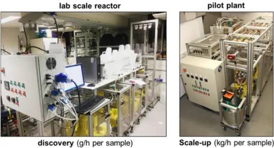
This thesis focuses on the synthesis, characterization and electrochemical evaluation of various nano-sized materials for use in high power and high energy lithium-ion batteries. The materials were synthesised via a continuous hydrothermal flow synthesis (CHFS) process, which is a single step synthesis method with many advantages including screening processes (chapter 5).
Electrochemical energy storage is introduced in chapter 1, with a focus on high power and high energy negative electrode materials for lithium-ion batteries (and capacitors). Many different classes of materials are discussed with associated advantages and disadvantages. This is followed by an experimental section in chapter 2.
Chapter 3 deals with the main question regarding why some high power insertion materials show a wider operational potential window than expected. The nature of this electrochemical performance is discussed and classified towards battery-like and supercapacitor-like behaviour. Chapter 4 deals with Nb-doped anatase TiO2, which was tested for high power insertion materials. The role of the dopant was discussed in a comprehensive study.
Chapter 5 gives an excellent example how CHFS processes can help accurately answer a scientific question. In this case the question dealt with the impact of transition metal dopants on the electrochemical performance of SnO2. Since CHFS enables similar materials properties despite doping, the real impact could be investigated in a fair manner. Finally, chapter 6 shows a strategy of achieving higher energy simultaneously with high cycle life. Insertion materials are combined with alloying materials in a simple, single step synthesis and this showed increased capacity, which is essential for high energy.
Acknowledgements
First, I would like to thank UCL, ASTAR and EPSRC for funding my PhD project. There were many people contributing in making the project so enjoyable during past three years, who are highlighted in the following:
I would like to thank my supervisor Jawwad Darr, who did an amazing job in controlling my
“messy” thoughts and directing them into something useful. I got lots of support and degree
of freedom during the past three years. Jawwad always helped me to get the most of the science I investigated and supported me in any possible way. Thanks for all endless discussions during the past three years, Jawwad!
Moreover, I would like to thank my other supervisors Dan Brett and Zhaolin Liu for supporting me as much as possible during any tricky challenges. Same applies for all the hidden geniuses at UCL and IMRE who always had an open mind for fruitful discussions, which include Martin Vickers, Jeremy Cockcroft, Steve Firth, Ding Ning, Afriyanti Sumboja, Michael Powell and so many more.
Our group at UCL was very supportive during the past years, no matter how far I was away. Therefore, I would like to thank Neel, Liam, Pete, Marco, Clement (TEM images in chapter 6.4.1), Ian, Dustin (electrochemical characterization for Figure 83a), Adrian, Tom, Kalyani, Charles, Carlos, Alistair, Paul, Jess, Eva and the guys from UCell. Dougal helped me during the lab movement of IMRE and supported me with needed scientific measurements and discussions (see XPS, BET and TEM analysis in chapter 6.4.2 and 6.4.3). Thanks Dougal, for all the help and input. Moreover, Juhun Shin is thanked for electrochemical characterizations for the results in chapter 3.
I would like to thank all the other helpful colleagues I met at ASTAR, which include Ceilidh, Ola (XPS analysis in chapter 3 and 6), Aled, Diana (SEM image in chapter 6.4.3), LP,
Davide, Andy, Sam, Will (I + II), Lizzy and so many more. Thank you all for the inspiring discussions and heads ups, when I got lost.
Being part of an exchange program was quite easy, simply because of all the helpful people organizing it. I would like to thank Zhimei Du, Jadranka Butorak and Yi Wen Teo for their endless efforts during the past three years.
Next, I would like to thank all the nice people I met during my PhD. Being part of a foreign society for only a few years can be a tricky adventure. Fortunately, I met so many kind and open people along the way in both UK and Singapore who made my stay very pleasant. Singapore was a great place to live and will always have a place in my heart. Special thanks to the lovely team mates from Football Plus and SMU.
Finally, “Danke an die Wehmer Fraktion”, who always got me back to reality. Also thanks to my second family, the Grevers. The “Ciao Bellas” should not be missed as well as most of
my friends including Andrea, Sebastian, Stefan, Ruth, Anne and so many more. I want to thank my family, which got a new, tiny member since my stay in Singapore. Heiner, Tina, Rita, Smita, Astrid and my dear lovely mum, simply thanks for all the support during the past years.
List of Publications
Publications related to the work presented in this thesis:
M. Lübke, D. Ning, C.F. Armer, D. Howard, D.J.L. Brett, Z. Liu, J.A. Darr, “Evaluating the Potential
Benefits of Metal Ion Doping in SnO2Negative Electrodes for Lithium Ion Batteries”, Electrochimica
Acta, 242, (2017) 400-407.
M. Lübke, D. Howard, C.F. Armer, A.J. Gardecka, A. Lowe, M.V. Reddy, Z. Liu, J.A. Darr, “High
energy lithium ion battery electrode materials; enhanced charge storage via both alloying and insertion
processes”, Electrochimica Acta, 231, (2017) 247-254.
M. Lübke, N. Ding, M.J. Powell, D.J. Brett, P.R. Shearing, Z. Liu, J.A. Darr, “VO2 nano-sheet
negative electrodes for lithium-ion batteries”, Electrochemistry Communications, 64, (2016) 56-60.
M. Lübke, A. Sumboja, I.D. Johnson, D.J. Brett, P.R. Shearing, Z. Liu, J.A. Darr, “High power nano -Nb2O5 negative electrodes for lithium-ion batteries”, Electrochimica Acta, 192, (2016) 363-369.
M. Lübke, P. Marchand, D.J. Brett, P. Shearing, R. Gruar, Z. Liu, J.A. Darr, “High power layered
titanate nano-sheets as pseudocapacitive lithium-ion battery anodes”, Journal of Power Sources, 305,
(2016) 115-121.
M. Lübke, J. Shin, P. Marchand, D.J. Brett, P. Shearing, Z. Liu, J.A. Darr, “Highly pseudocapacitive
Nb-doped TiO2 high power anodes for lithium-ion batteries”, Journal of Materials Chemistry A, 3,
(2015) 22908-22914.
M. Lübke, I. Johnson, N.M. Makwana, D.J. Brett, P. Shearing, Z. Liu, J.A. Darr, “High Power TiO2
and High Capacity Sn-doped TiO2 Nanomaterial Anodes for Lithium-ion Batteries”, Journal of Power
Sources, 294, (2015) 94-102.
Other Publications:
M. Lübke, A. Sumboja, L. McCafferty, C.F. Armer, A.D. Handoko, Y. Du, K McColl, F. Cora, D.
Brett, Z. Liu, J.A. Darr, “Transition metal doped α-MnO2 nanorods as bifunctional catalysts for
efficient oxygen reduction and evolution reactions” ChemistrySelect (2018).
A. Sumboja, M. Lübke, Y. Wang, T. An, Y. Zong, Z. Liu, “All-Solid-State, Foldable, and Rechargeable Zn-Air Batteries based on Manganese Oxide Grown on Graphene Coated Carbon Cloth
Air Cathode” Advanced Energy Materials, (2017) 1700927.
C.F. Armer, M. Lübke, M.V. Reddy, J.A. Darr, X. Li, A. Lowe, “Phase change effect on the structural
and electrochemical behaviour of pure and doped vanadium pentoxide as positive electrodes for
lithium ion batteries”, Journal of Power Sources, 353, (2017) 40-50.
I.D. Johnson, M. Lübke, O.Y. Wu, N.M. Makwana, G.J. Smales, H.U. Islam, R.Y. Dedigama, R.I. Gruar, C.J. Tighe, D.O. Scanlon, F. Corà, J.A. Darr, “ Pilot-scale continuous synthesis of a vanadium-doped LiFePO4/C nanocomposite high-rate cathodes for lithium-ion batteries”, Journal of Power
M. Lübke, N.M. Makwana, R. Gruar, C. Tighe, D. Brett, P. Shearing, Z. Liu, J.A. Darr, “High capacity
List of Abbreviations AC Activated Carbon BET Brunauer Emmett Teller CV Cyclic voltammetry
CHFS Continuous Hydrothermal Flow Synthesis CJM Confined jet mixer
DEC Diethyl carbonate DFT Density functional theory DMC Dimethyl carbonate EC Ethylene carbonate
EDLC Electrochemical double layer capacitor EDX Energy dispersive X-ray
EIS Electrochemical impedance spectroscopy ESW Electrochemical stability window LCO Lithium cobalt oxide
LFP Lithium iron phosphate LiB Lithium-ion battery LiC Lithium-ion capacitor LFP Lithium iron phosphate
NCM Lithium nickel cobalt manganese oxide PXRD Powder X-ray diffraction
SEI Solid electrolyte interphase SEM Scanning electron microscopy TEM Transmission electron microscopy TGA Thermogravimetric analysis XPS X-ray photoelectron spectroscopy XRF X-ray fluorescence
1
Table of Contents
1. Introduction ...5
Motivation ... 5
1.1 Electrochemical Basics for Electrochemical Energy Storage ... 8
1.2 Electrochemical Energy Storage Devices ... 10
1.3 1.3.1 Lithium-ion Batteries (LiBs) ...11
1.3.2 Electrochemical Capacitors ...13
1.3.3 Hybrid Energy Storage Devices and Electrodes ...17
Electrode Materials for LiBs ... 20
1.4 1.4.1 Insertion Materials ...25
1.4.2 Conversion Materials ...28
1.4.3 Alloying Materials ...31
1.4.4 Combinations of Insertion / Alloying / Conversion Materials ...33
1.4.5 Tin Dioxide – An Alloying and Conversion Material? ...34
Pseudocapacitive Battery Materials ... 36
1.5 1.5.1 Pseudocapacitance Insertion – Impact of Surface Area and Defects ...38
1.5.2 Niobium Pentoxide for High Power LiBs ...40
1.5.3 Layered Titanates for High Power LiBs ...41
1.5.4 Vanadium Dioxides for High Power LiBs ...43
Solid Electrolyte Interphase (SEI)... 44
1.6 Advantages and Disadvantages of “going nano” for LiBs ... 48
1.7 Synthesis Methods of Nano-Materials ... 50
1.8 1.8.1 Hydrothermal Methods ...51
1.8.2 Introduction to Continuous Hydrothermal Flow Synthesis ...55
Aims and Objectives ... 60
1.9 Experimental Methods ...61
2. Experimental Overview for CHFS ... 61
2.1 2.1.1 Freeze drying ...62
Physical Characterization ... 64 2.2
2
2.2.1 Powder X-Ray diffraction (PXRD) ...64
2.2.2 X-ray photoelectron spectroscopy (XPS) ...65
2.2.3 Raman spectroscopy ...66
2.2.4 Scanning electron microscopy (SEM) ...67
2.2.5 Transmission electron microscopy (TEM) ...68
2.2.6 Energy Dispersive X-ray Spectroscopy (EDX)...69
2.2.7 X-ray fluorescence (XRF) ...69
2.2.8 Surface area determination after Brunauer, Emmet and Teller (BET) ...70
2.2.9 Thermogravimetric analysis (TGA) ...71
Electrochemical characterization ... 72
2.3 2.3.1 Electrode fabrication and testing ...72
2.3.2 Cyclic Voltammetry (CV) ...74
2.3.3 Galvanostatic measurements ...75
2.3.4 Electrochemical Impedance Spectroscopy (EIS) ...76
2.3.5 Characterization of the charge storage mechanism ...78
High Power Negative Electrode Materials for LiBs – Expanding the operational potential 3. window ...81 Aims ... 81 3.1 Introduction ... 81 3.2 Experimental ... 83 3.3 3.3.1 Synthesis of the Materials ...83
3.3.2 Experimental Characterization ...84
3.3.3 Electrochemical Testing ...85
Results and Discussion ... 87
3.4 3.4.1 Characterization Results – Nb2O5 ...87
3.4.2 Characterization Results – Layered Titanate...89
3.4.3 Characterization Results – VO2 ...93
3.4.4 Understanding the Charge Storage Properties (0.05 – 3.0 V vs. Li/Li+) ...96
3.4.5 General Electrochemical Performance (0.05 – 3.0 V vs. Li/Li+) ...101
3.4.6 The Role of Carbon Black Additive on the Performance of the Overall Electrode 108 Overall Discussion and Outlook ... 111 3.5
3 High Power Negative Electrode Materials for LiBs – Combining Niobium and Titanium 4. Oxides ...114 Aims ... 114 4.1 Introduction ... 114 4.2 Experimental ... 115 4.3 4.3.1 Synthesis of the Materials ...115
4.3.2 Experimental Characterization ...116
4.3.3 Electrochemical Testing ...117
Results and Discussion ... 118
4.4 4.4.1 Characterization Results ...118
4.4.2 Understanding the Charge Storage Properties (1.2 – 3.0 V vs. Li/Li+) ...121
4.4.3 General Electrochemical Performance (1.2 – 3.0 V vs. Li/Li+) ...125
Overall Discussion and Outlook ... 129
4.5 Transition Metal Ion Dopants in SnO2 – Useful for High Energy LiB Full Cells? ...130
5. Aims ... 130 5.1 Introduction ... 130 5.2 Experimental ... 132 5.3 5.3.1 Synthesis of the Materials ...132
5.3.2 Experimental Characterization ...132
5.3.3 Electrochemical Testing ...133
Results and Discussion ... 135
5.4 5.4.1 Characterization Results ...135
5.4.2 The Role of Carbons in SnO2 Electrode Networks ...141
5.4.3 Electrochemical Performance Evaluation of the doped SnO2 materials via Cyclic Voltammetry ...143
Overall Discussion and Outlook ... 149
5.5 Stable, High Energy Negative Electrode Materials for LiBs - Combinations of Insertion and 6. Alloying Materials ...151 Aims ... 151 6.1 Introduction ... 151 6.2 Experimental ... 152 6.3
4
6.3.1 Synthesis of the Materials ...152
6.3.2 Experimental Characterization ...154
6.3.3 Electrochemical Testing ...155
Results and Discussion ... 156
6.4 6.4.1 Characterization Results – Sn-doped TiO2 ...156
6.4.2 Characterization Results – Sn-doped Nb2O5 (pilot plant synthesis)...159
6.4.3 Characterization Results – Sn-doped VO2 (pilot plant synthesis) ...161
6.4.4 Electrochemical performance - Sn-doped TiO2 ...164
6.4.5 Electrochemical performance - Sn-doped Nb2O5 ...170
6.4.6 Electrochemical performance - Sn-doped VO2 ...172
Overall Discussion and Outlook ... 177
6.5 Conclusions and Future Directions ...179
7. I. References ...182
II. List of Figures ...196
5
1.
Introduction
Motivation
1.1
There are currently high motivations for drastic changes in the energy market. The increasing population (corresponding to an increasing demand of energy), global warming and the decreasing availability of natural resources pose a big challenge for humanity. In 2007, approximately 68 % of the electrical energy was supplied from fossil fuels (coal 42 %, natural gas 21 %, oil 5 %), 14 % from nuclear, 15 % from hydro, and the remaining 3 % was supplied by renewable energy tech [1]. One strategy towards sustainable energy markets is the increased use of renewable energy sources (solar and wind energy). But the sun does not shine overnight (or with the same intensity every day) and wind does not blow every day with the same speed (Figure 1a).
Figure 1: a) Daily profiles of average sun light in hours and average wind speed in km h⁻1 per day (January
2017, data obtained at London Heathrow Airport; weatheronline.co.uk). b) Classifications of potential electrical storage mechanisms for stationary applications.
6 Therefore, smart grid solutions have to be established including efficient energy storage systems in terms of cost, power, long-life and so on. Electrical energy can be stored directly via physical double layer charges in electrochemical double layer capacitors (EDLC) or indirectly via conversion in kinetic, potential or chemical energy (Figure 1b). Batteries seem to be very promising for the storage of electrical energy when considering high energy efficiencies and densities. Because of their high specific energy, lithium-ion batteries (LiBs) are considered to be the most promising solution for many kinds of energy storage applications.
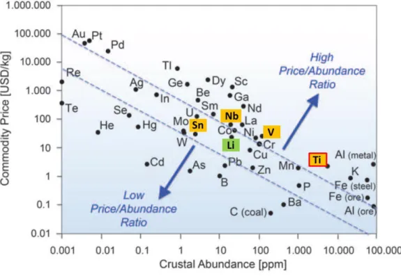
Figure 2: Relationship between metal price and its relative abundance in the Earth's upper continental crust (based on abundance of Si: 106 atoms). The metal price data from 2013. Modified taken from ref [2].
7 Although LiBs are established commercial products, further research and development is still needed to improve the performance in terms of energy density, cost, rate capability and safety; especially considering that LiBs are expected to play a key role in electric vehicles. In addition to safety issues with the electrolyte, current commercial LiBs (ca. 200 Wh kg⁻1), would exceed a
weight of 800 kg for 1000 km. New electrode materials with far higher specific capacities need to be investigated in order to decrease such high weight to less than 400 kg. Moreover, energy storage needs to be affordable.
In Figure 2, the metal prices from April 2015 are plotted. E.g. for the negative electrode of a LiB, graphite is still used due to its high theoretical capacity (372 mAh g⁻1), high electronic
conductivity and low price. But there are several issues such as high lithium-ion loss during the initial cycles, low safety due to lithium plating and also poor power performance, which force the development of alternative safe electrode materials. The plot indicates why elements like titanium are interesting simply due to high abundance and low costs. Herein, various metal oxides are investigated for different applications towards high power and high energy devices.
High power is very important, as the customer does not want to charge their car or phone for many hours (which would be a huge drawback compared to conventional fuel based cars; please note that many current, conventional battery packs for electric vehicles show a continuous charge power capability of less than 1C) and high energy is also important, as the customer does not want to recharge the phone or car after a short period of usage time. Moreover, there are also different applications needing only high power or high energy. Thus, even for LiBs, the variety of possible combinations is huge and will be introduced during chapter 1. The cost of each material should be kept in mind.
8
Electrochemical Basics for Electrochemical Energy Storage
1.2
Energy can be stored physically and chemically in electrochemical energy storage devices. For the electrochemical energy storage, the reaction Gibbs energy ∆G [J mol⁻1] represents the useful
energy available from a reaction and can be seen as the maximum work an electrochemical device can deliver.
∆! = −$%∆&
(1)∆! is related to the potential difference ∆&, the Faraday constant % (% = 96485 '
()*) and the
numbers n of transferred electrons per mol (Equation 1). A negative ∆G represents a spontaneous reaction like an electrochemical discharge step. The reaction Gibbs energy ∆! can be related to other parameters, such as temperature or pressure (Equation 2).
∆! = ∆!
,+ R. ln /
0102
3
(2)∆!, is the maximum work under standard conditions, 7 the gas constant (7 = 8.3145 > ()* ?), .
the temperature, @A the activity of the product and @B the activity of the reactants. The combination of Equation 1 and Equation 2 gives the Nernst equation (Equation 3). The Nernst equation allows the calculation of the potential & [V], where the standard potential &, of each
material can be found in literature.
& = &
,−
BC DEln(
01
02
)
(3)When the potential of the positive and negative electrode is known, the cell potential can be calculated (Equation 4).
9
∆& = &
AHIJKJLM− &
NMO0KJLM (4)The theoretical specific capacity PKQS(TU
W X of each electrode material is a very important
parameter for the energy of a full cell. A high specific capacity material results from a low molar massY combined with a high number of transferred electronsZ(Equation 5), note 1 C = 1 As.
P
KQ=
\.^ _DE (5)Finally, the theoretical specific energy of an ideal battery ` [aU
bW] is the product of the cell
potential ∆&and the theoretical specific capacity PKQ (Equation 6). Therefore, the increase of the cell voltage and the specific capacity results in higher energy densities [3].
` = ∫ ∆& de
fghij,
≈ P
KQ∆&
(6)The specific power is in addition to the specific energy a very important characteristic for many applications. This can be described as the maximum energy a device can store and release within very short time.
10
Electrochemical Energy Storage Devices
1.3
An ideal energy storage device provides a long cycle life, high specific power and energy (which means the mass of the device is very low), environmental compatibility, high safety and low costs. So far, there are four main electrochemical energy storage systems (redox-flow batteries are not considered herein, as the focus is set on non-continuous charge storage). Capacitors and electrochemical capacitors store the charge physically (electrochemical pseudocapacitors store the charge also chemically) at the surface and these are high power devices with a high cycle life (up to 1,000,000 cycles). These devices show low specific energy compared to batteries and fuel cells. Batteries store the charge chemically and have medium cycle life (up to 10,000 cycles depending on the electrode materials, see discussion later) and less specific power [4].
Figure 3: Specific power versus specific energy for different energy storage devices (Ragone plot modified taken from [3, 5]).
11 Specific power and specific energy are often inversely related. The specific energy decreases with higher specific power and vice versa. Reaching higher specific power and specific energy under acceptable cycle life conditions at once is still a challenge (see Ragone plot in Figure 3).
1.3.1 Lithium-ion Batteries (LiBs)
Compared to other battery systems, LiBs show higher gravimetric and volumetric energy density due to the low atomic weight of lithium-ions (Figure 4). Moreover, using lithium results in large cell potentials, because of its very low standard potential, which therefore increases the energy density (see chapter 1.2). Besides the high worldwide abundance of Li (e.g. two times higher than Pb), all these characteristics make LiBs an attractive secondary energy storage system.
Figure 4: Comparison of the different battery technologies in terms of volumetric and gravimetric energy density (modified taken from [6]).
12 The first commercial rechargeable LiBs on the market were sold by Sony in 1991 [7]. A typical LiB consists of graphite as negative electrode and a layered transition metal oxide [such as LiCoO2, (LCO) previously and more recently LiNi1/3Co1/3Mn1/3O2, (NCM)] as the positive electrode. The charge is stored via lithium-ions which move during charge from the positive to the negative electrode and intercalate between the graphene layers (Figure 5). Theoretically, one lithium-ion can be intercalated for every six carbon atoms.
Figure 5: The principle of operation of the first commercialized LiBs. Lithium-ions move from the negative to the positive electrode during discharging (it is vice versa for charge).
Note: An anode and a cathode are defined according to oxidation and reduction reactions, respectively. During discharge of a LiB, these terminologies are correct. As soon the battery is charged, these terminologies are incorrect, because the anode and cathode switch roles. The first batteries were all primary, which explains why the incorrect terminologies of “anode” and “cathode” for secondary batteries are still used by the majority of electrochemists [8].
The negative and positive electrodes are separated by a separator soaked with an organic electrolyte containing lithium-ion salt. The electrolyte should show high lithium-ion conductivity and also good safety performance such as low vapour pressure and high flash point. Mixtures of
13 ethylene carbonate (EC) and dimethyl carbonate (DMC) can exhibit some of these characteristics best, but they are flammable. Lithium hexafluorophosphate (LiPF6) is used as lithium salt in the electrolyte, because it still possesses the best compromise in terms of solubility, electrochemical stability and also the ability to inhibit anodic dissolution at the aluminium current collector at the positive electrode side. LiPF6 is thermally (>60 °C) and chemically (with H2O traces) unstable causing safety issues. In combination with the EC solvent, LiPF6 is also able to form an effective Solid Electrolyte Interphase (SEI), which was the key development for the use of graphite in LiBs. The SEI layer acts as a protection layer, which is able to prevent exfoliation of the graphene layers and it also prevents further electrolyte decomposition after the initial cycles (see more details in chapter 1.6).
1.3.2 Electrochemical Capacitors
Electrochemical capacitors can be classified into two groups, namely electrochemical double layer capacitors (EDLCs) and pseudocapacitors (also called oxide supercapacitors), Figure 6.
EDLCs store their charge physically, which dramatically increases the cycle life compared to batteries as there is no chemical degradation. Therefore, EDLCs show their main advantages in high specific power and very long stable cycle life. These characteristics are excellent for applications which require high power and high reliability. Examples include container trains at harbours, regenerative breaks in cars, emergency doors in air planes, defibrillators or the use for energy conversion in smart grids and also public electric busses where charging occurs at each station.
14
Figure 6: Scheme of possible electrochemical capacitors. The charge storage mechanism can be divided in two main characteristics, e.g. physically stored charged for EDLCs and chemically stored charge for pseudocapacitors.
In 1957 Becker patented a system using a high specific surface area carbon, coated on a metallic current collector [9]. This system provided a very high capacitance. This behaviour could be explained by the known idea of the Helmholtz double layer. Ions move during charge to each electrode with reversed charge and form a double layer at each high surface area electrode. During discharge, ions diffuse back into the electrolytic system as a result of the entropic force. Therefore, the charge is stored only electrostatically via charge separation at the electrode/electrolyte interface.
The capacitance m of a double layer depends on the surface area o, the effective thickness of the double layer p and the dielectric constant of the electrolyte qr and of the vacuum q,:
15
m = q
rq
,st (7)Activated carbons (AC) are widely used as EDLC electrode materials today due to their high surface area (up to 3500 m2 g⁻1), which drastically increases the double layer capacitance
(Equation 7). They also offer low costs, high conductivity and electrochemical stability [10, 11].
The specific energy and specific power are related to the maximum cell voltage V and the series resistant R of the whole cell (Equation 8, 9). The resistance is the total of electrolyte resistance, particle-particle resistance, contact resistance between current collector and active material and the resistance of the electrolyte within pores of the active material [12, 13].
&
u0v=
wxm y
x (8)z
u0v=
{|
}B (9)
Electrolytes used in commercial EDLCs contain quaternary ammonium salts such as tetraethyl ammonium tetrafluoroborate (TEABF4) in propylene carbonate (PC) or acetonitrile. The advantage of organic electrolytes compared to the aqueous electrolytes is the higher achievable cell voltage. Using aqueous electrolytes limits the cell voltage to 1.2 V, whereas organic electrolyte can typically be used up to 2.7 V [14-16]. But, organic electrolytes tend to have a lower dielectric constant, which results in a lower capacitance (Equation 7). Using ionic liquids (ILs) can increase the electrochemical stability window compared to organic electrolytes [17]. They also have a wide thermal stability, high ionic conductivities, are volatile and non-flammable, but it has also disadvantages compared to PC based electrolytes. The conductivity at lower temperatures is much lower and they are also more expensive [17-20]. An alternative
16 approach is a mixture of ILs and organic solvents [20] or highly concentrated (e.g. NaTFSI) aqueous electrolytes which increases the cell voltage of such systems up to 1.8 V [21].
A new class of high energy oxide supercapacitor electrodes are certain transition metal oxides (e.g. TiO2, V2O5, RuO2, Fe3O4). The charge can be stored via electrochemical Faradaic reactions between the electrode material and ions in the appropriate potential window. This is called pseudocapacitance [5]. When a potential is applied to these materials, fast and reversible Faradaic reactions (redox reactions) take place at the surface. In addition to that, there is of course also some charge storage originating from a Helmholtz double layer. In general, the Faradaic stored charge can be ten to hundred times higher than the Helmholtz double layer charge [22].
Pseudocapacitive materials can be classified as intrinsic and extrinsic. Intrinsic pseudocapacitive materials (RuO2, MnO2, Nb2O5 etc.) display the features of capacitive charge storage for a wide range of morphologies and particle sizes (surface areas). Extrinsic pseudocapacitive materials (e.g. TiO2) show high dependence on morphologies and especially particle size (surface area) [23]. In the latter, the bulk materials do not show any pseudocapacitive charge storage and upon nano-sizing (increasing the surface area), the charge storage shifts towards pseudocapacitance due to decreased lithium-ion diffusion at the surface and also within the particle [24].
It should be noted, that any of the aforementioned charge storage devices (with charge storage arising from any surface effects), has a massive drawback of self-discharge [25-27]. This means that the full cell would lose some of its energy in its charged stage over time.
17 1.3.3 Hybrid Energy Storage Devices and Electrodes
In Table 1, the features of EDLCs and LiBs are compared and summarized. EDLCs are more interesting for applications that require high power and long cycle life, whereas applications, that need high energy, would require the implementation of LiBs. Oxide supercapacitor materials (pseudocapacitive materials) are also high power materials, but they show more charge storage via chemical reactions at the surface, increasing the energy density. Thus, oxide supercapacitor materials show features in-between batteries and EDLCs [28].
Table 1: Comparison of EDLCs and LiBs (data partly derived from https://www.supercaptech.com/battery-vs-supercapacitor, 26/06/2017).
EDLCs LiBs
charge storage mechanism physical chemical
charge time seconds minutes
discharge time seconds minutes
energy efficiency >99 % >95 %
cycle life >500,000 >1,000 (@ 1 C)
self-discharge (per month) 40-50 % 2 %
specific energy (Wh kg⁻1) 4-10 80-260
specific power (kW kg⁻1) 5-40 1.5
cost per Wh 10-20 US$ 1-2 US$
cost per kW 25-50 US$ 75-150 US$
The term “hybrid” can be used if two or more technologies are combined in order to get the
advantages of these in one. The need for devices offering both high energy and power is getting a more and more important research topic. Therefore, the attributes of LiBs and supercapacitors can be combined in parallel and in series [29], Figure 7.
18
Figure 7: Scheme of possible approaches combining the positive attributes of batteries and electrochemical capacitors. The serial combination includes the use of a LiB and an EDLC electrode material. The parallel combination uses different storage mechanism in one electrode (composite material or simply some nano-sized insertion materials, see chapter 1.5).
The serial combination, e.g. the use of a battery electrode and a double layer capacitive electrode, leads to many advantages. These devices, called asymmetric capacitors, hybrid capacitors or lithium-ion capacitors (LiCs), show a higher specific energy compared to conventional EDLCs and can also display higher power compared to LiBs. Moreover, the cycling stability [30] and rate performance [31, 32] can be improved compared to LiBs. The reason for this behaviour can be found in the high rate capability and high cycle stability of the EDLC electrode [33]. Therefore, the C-rate performance of the cell is mostly related to the performance of the battery electrode in such a device, meaning the C-rate performance is only limited by one electrode material in the system. Another hybrid device is the setup of an AC as the negative electrode and LiB electrode as positive material (e.g. LFP, LCO).
Most current LiCs contain a LiB negative electrode material and an EDLC positive electrode material. The reason for this system is the win of additional full cell voltage, because AC can be easily used in the full width of the electrochemical stability window of the organic electrolyte
19 (up to 4.4 V vs. Li/Li+). Common AC electrode active materials in EDLCs are still limited by the electrolyte decomposition at low applied potentials for carbonate-based electrolytes [15]. Using negative electrode materials with low de/lithiation potentials vs. Li/Li+ should lead to much higher cell voltages when the electrolyte is stable in this system (up to 4.4 V [34]). Published systems include the use of graphite [31, 32, 35], soft carbon [36-38], hard carbon [39], and many more for full cell LiCs with AC on the positive electrode side. Beside graphites or amorphous carbons also other negative electrode materials such as lithium titanate (LTO), lithium vanadium phosphate [40] or Fe2O3 [41] were investigated for LiCs .
The parallel combination deals often with the use of composite electrode materials. These may contain two different active materials. Electrodes containing LiB and EDLC electrode materials are one example, as they store the charge chemically and physically. In Equation 9, the leading role of the cell resistance on the power performance was pointed out. The reduction of the electronic resistance of the electrode material was achieved through adding AC leading to far improved rate capability [42]. Cericola et al. showed improved rate capabilities for the composite electrode material based on LiMn2O4 and AC compared to each active material on its own [29]. Böckenfeld et al. proposed a composite electrode based on LFP and AC [43]. Finally, a parallel combination can be simply reached through nano-sizing various known insertion negative electrode materials. The idea behind is activating extrinsic supercapacitor materials (insertion battery materials) and will be introduced in chapter 1.5. Therefore, it is even possible to make hybrid devices with hybrid electrodes (e.g. nano-sized insertion materials as negative electrode versus AC as positive electrode). Herein, each group of electrode materials for LiBs will to be introduced first.
20
Electrode Materials for LiBs
1.4
For LiBs, high energy densities can be achieved via a high cell voltage. This includes a high potential vs. Li/Li+ for the positive electrode material and a low potential vs. Li/Li+ for the negative electrode material. In Figure 8, different potentials for each positive electrode material are presented. Lithium iron phosphate (LFP) is non-toxic and shows excellent rate capabilities, but compared to it, lithium cobalt oxide (LCO) and nickel cobalt manganese oxide (NCM) are electrochemically active at higher operating potentials. Another approach for higher energy density cells is the increase of the specific capacity. This specific capacity can be calculated based on Equation 5 (chapter 1.2). Today, developing high capacity positive electrode materials is still a big challenge. Positive electrode materials can theoretically deliver up to 350 mAh g⁻1
(lithium vanadium oxides). On the negative electrode side, much higher theoretical specific capacity materials are under investigation. As long the positive electrodes cannot deliver higher capacities, the potential energy win is limited if high capacity negative electrode materials are used. This is simply due to the fact that more positive electrode material (which is often also more expensive) would be needed to balance the full cell energy storage.
There are many examples for possible new negative electrode materials beside the commonly used graphite (372 mAh g⁻1), such as conversion materials (e.g. transition metal oxides like
Fe2O3 1,007 mAh g⁻1; Fe3O4 926 mAh g⁻1), alloying materials (group IV elements such as
Si 3572 mAh g⁻1; Sn 993 mAh g⁻1) or lithium metal (3,840 mAh g⁻1). Conversion and alloying
materials tend to suffer from large structural changes including massive volume expansion during cycling, which leads to high capacity losses and generally low cycle stability. Lithium metal as negative electrode material still shows high safety risks due to dendritic lithium formation and electrolyte destruction. The latter seems to be partly solved with the inclusion of ionic liquids.
21
Figure 8: Current investigated and established electrode materials for LiBs (modified taken from [44]).
High specific energy and high power are key characteristics for various battery applications. Some applications need high energy and some need high power (and some need simultaneously both). While the energy density of the battery is the product of the specific capacity and the overall cell voltage, the power density is the measure of the rate at which energy can be stored and released from a system.
Towards high energy negative electrode materials. High energy density can be achieved both
via a high cell voltage and high specific capacities (see chapter 1.2, Equation 6). As shown later, the highest energy negative electrode materials are alloying and conversion materials. These can store far more lithium-ions compared to insertion materials, simply due to the ability of massive structural changes during reversible lithiation, and they often show a far lower operating potential compared to transition metal oxide based insertion materials.
22
Towards high power negative electrode materials. High power can be described as the
maximum stored charge even at very high C-rates (Figure 9). The C-rate is correlated to the theoretical capacity of each electrode material. A C-rate of 1C corresponds to an applied current to fully charge the electrode material within 1 h. Therefore, charging or discharging at 2C corresponds to 30 min and C/2 to 2 h. As an example, a LFP electrode has an active material mass loading of 2 mg. The theoretical capacity is 170 mAh g⁻1. So for 1 C the applied current is
0.34 mA. Slow reactions including massive structural changes are not optimized for high power performances (but it is still questionable what smallest possible particle size might do in future), which also explains why insertion materials are generally far more suitable for usage as high power electrodes at the moment. These materials show very low structural changes upon lithiation and have a very high cycle life.
Figure 9: Schematic plot of the capacity versus C-rate for high and low power materials.
The total amount of stored charge for such high surface area metal oxides can be separated into Faradaic contribution of the lithium-ion insertion process, pseudocapacitance (Faradaic charge-transfer process with surface atoms) and the non-Faradaic contribution from the double layer charging. Wang et al. reported an increase of stored charge via pseudocapacitance and a decrease
23 of stored lithium-ions inserted into the structure at higher applied current rates. This effect was shown to increase with reduced crystallite size and higher surface area [24]. Thus, some insertion battery materials tend to act more like oxide supercapacitor materials at highest applied current rates (fast charging/discharging).
Figure 9 shows a scheme of the general performance of a high power and low power electrode material. A high power electrode material has to possess high solid-state ion diffusivity, high electrical conductivity, minimized solid-state path lengths for ion transport, minimized path lengths for electron transport and finally a high electrode/electrolyte surface area [45], (Figure 10). According to this, low particle sizes and high surface areas favour the high power performance of an electrode material.
Figure 10: Exemplary presentation of the solid state diffusion and path length in electrode materials.
Guo et al. made a comprehensive review about benefits of nano-sized particles for high power LiBs [46]. Solid-state diffusion of lithium-ions within the electrode materials can be expressed as the mean diffusion (or charge storage) time (~uM0N). ~uM0N is related to the diffusion coefficient
€ and the diffusion length •, Equation 10:
~
uM0N=
‚|
24 Therefore, two approaches can be taken for fast charging/discharging. One can either drastically increase the ion diffusion € or decrease the diffusion length •. Improved diffusion can be related to doping, that can widen the lithium-ion paths within the structure. Such approaches are quite challenging as the optimum dopant atom and amount needs to be investigated. Less challenging seems to be the simple approach of nano-sizing for decreased solid-state diffusion. Guo et al. further pointed out, that a reduction of • from 10 mm (typical size of some commercial electrode materials) to 100 nm can drastically reduce t(…†‡ from 5000 to 0.5 s (material with
€ =10⁻10 cm2 s⁻1, which is a typical value of electrode materials) [46]. The effects are huge,
explaining the efforts of R&D in the field of nano-sized electrode materials for LiBs. In the following section, different classes of negative electrode materials will be presented. Insertion materials can be seen as high power and conversion/alloying materials as high energy materials. In addition to this (considering an appropriate mass loading and no additives within the electrode network), insertion materials have very high cycle lives, but low theoretical capacities (low structural changes), whereas conversion/alloying materials have low cycle lives but high theoretical capacities (high structural changes), see Figure 11.
Figure 11: Scheme for comparison of insertion versus conversion/alloying materials. Insertion materials are stable but show low specific capacity whereas conversion/alloying materials show low stability but high specific capacity.
25 In 2005, Sony developed its Nexelion battery using a negative electrode material mainly composed of a Sn/Co/C composite synthesised by a high energy mechanical milling process [47]. Not only composite materials, but also nano-sized particles and nano-structured materials have been suggested to alleviate the mechanical strain generated due to the volume change as the lithium-ions are inserted into and extracted from the host electrode materials [48, 49]. This development reflects the idea of composites for high cycle life and high capacity electrode materials, see also various commercially available Si/grahite based LiB cells.
1.4.1 Insertion Materials
The general, lithium-ion insertion into a transition metal oxide MOŠis presented in Equation 11 (note that this reaction is also possible for sulphides, phosphates etc.). Characteristic for this process is a high cycle life, high safety but low or medium capacity.
MOŠ + yLiŽ+ ye•↔ Li’MOŠ (11)
The term insertion can be used for the reversible lithiation in 1D-olivine (e.g. LFP, rutile TiO2), 2D-layered (e.g. graphite, layered titanate) and 3D-spinel (e.g. LTO, LMO) structures, whereas the term intercalation is specifically only applicable for 2D layers (Figure 12).
26 Insertion materials are ionic/electronic conductors. The ionic transport of the host insertion material is enabled by providing diffusion channels for the lithium-ions and inter-connections of interstitial sites. The electronic transport results from the overlapping of the d orbitals of the (transition) metal. These metals also enable charge compensation during lithiation and delithiation due to its reduction and oxidation, respectively.
There are two processes of lithium-ion insertion. One is a mono-phase homogenous process, where the lithium-ion insertion does not affect the host structure and causes only minimal structural changes (see graphite). The second one is a bi-phase process, where structural rearrangement may involve either a simple reorganization of the lithium-ions within the interstitial sites or the displacement of the transition metal or even the deformation of the anionic sub lattice (see LFP, rutile TiO2).
Graphite as benchmark negative electrode. The low intercalation/deintercalation potential vs.
Li/Li+ of graphite and the high cycle stability have led to its use as negative electrode in LiBs. During intercalation the graphene layers shift to the favoured AA stacking and the interlayer distance increases around 10 % [50]. These structural changes are far lower compared to alloying and conversion reactions (up to 300 %). Graphite is relatively inexpensive, has a high specific theoretical capacity of 372 mAh g⁻1 and operates at relatively low potentials (range of
0.3 to 0.1 V vs. Li/Li+). However, formation of a SEI at the surface is necessary to stabilise the negative electrode material, and poor rate retention at applied currents >5 C [30, 51-53]. Due to kinetic limitations during the intercalation of lithium-ions between the graphene layers [32], graphite can suffer in terms of safety, e.g. lithium plating and dendrites can be formed, which can lead to short circuits [54].
27
Titanates as alternative to graphite. Titanium oxide based materials are very interesting for
lithium-ion based electrochemical energy storage systems since their insertion operating potential is in the range 1.0 to 2.5 V vs. Li/Li+, giving higher safety (no risk of lithium dendrite formation). TiO2 (ca. 168 mAh g⁻1 for anatase TiO2) and LTO (175 mAh g⁻1) offer good
sustainability, low cost, low risk to the environment, high cell safety, low capacity loss, high power capability and a very high cycle life due to minimal volume and structural changes during cycling [55]. However, the higher operational potential window dramatically decreases the specific energy of a full cell [56, 57]. Therefore, titanium oxide based LiB materials are the first choice, if power performance, cycle stability, cost or safety are needed parameters. Anatase TiO2 is very easy to synthesize, which explains the commercial interest in it for electrochemical energy storage devices [24, 58-63]. Anatase TiO2 has a body centred space group I41/amd, which is comprised of TiO6 octahedra sharing two adjacent edges with two other octahedral so that planar double chains are formed [64]. The diffusion of lithium-ions is very facile along a diffusion path connecting the octahedral interstitial sites [65]. 0.5 mol of lithium-ions can be stored per 1.0 mol anatase TiO2, which is accompanied with a symmetry transformation towards orthorhombic Pmn21 space group [66] and a unit cell increase along the b-axis (decrease along the c-axis) which overall expands the unit cell volume by only 4 % [67]. The Ti3+/4+ redox reactions take place at ca. 1.6 V vs. Li/Li+ during lithiation and ca. 2.0 V vs. Li/Li+ during delithiation.
28 1.4.2 Conversion Materials
In 2000, Poizot et al. investigated various metal oxides (such as CoO and FeO) as negative electrode materials and measured very high capacities of 700 mAh g⁻1 [68]. It could be shown
that during charge the metal oxide was fully converted to its metallic state. Because of this behaviour, these new electrode materials were called conversion materials. The M†X” [M = metallic cation, X = anion (S, N, P, O, F)] is reduced to its metallic form surrounded by a gel-like lithium compound Li‡X (see Equation 12 and Figure 13).
M†X”+ (b ∙ n)LiŽ ↔ aM + b Li‡X (12)
One reason for the reversibility (similar amount of lithium-ions are stored and released in the electrode material during cycling) is the enhanced surface energy of the nano-dispersed transition metal particles after reduction (these might have a catalytic effect) [69]. Different from oxides and sulfides, the main exception is fluoride, which reacts at high values close to 3.0 V vs. Li/Li+, which makes it a candidate for positive electrode materials [70].
Figure 13: Schematic presentation of the lithiation/delithiation of CoO particles. During the first discharge step a gel-like layer is transformed next to metallic Co particles and Li2O (modified taken from [71]).
29 The range of possible conversion materials is very large and has been widely explored. Fe2O3 (1007 mAh g⁻1) and Fe3O4 (926 mAh g⁻1) have high theoretical capacities, are non-toxic and
environmentally friendly, highly abundant and inexpensive, which is why these are very interesting candidates for future negative electrode materials in LiBs. However, many of these materials suffer from poor voltage hysteresis and large volume changes upon cycling (causing morphological/structural changes in the negative electrode network) which is observed as large capacity fading [72]. A voltage hysteresis can be understood as a significant shift of the electrochemical potential activity from low potentials during lithiation towards high potentials during delithiation for the negative electrode side (Figure 14).
Figure 14: Scheme for representation of the voltage hysteresis (ΔE) during lithiation and delithiation and
also showing the impact of crystallinity loss for such conversion materials (scheme herein refers to iron oxides).
In Figure 14, the initial cycling data for the first two cycles of a general conversion material like iron oxides is presented. During initial lithiation, the voltage hysteresis is even higher because the activation energy is higher. The crystalline material undergoes drastic structural changes, which causes additional lithium-ion losses due to irreversible lithiation sites within the structure. For iron and cobalt oxides, the initial voltage hysteresis can be around 1.7 V, which is far higher
30 compared to graphite with <0.1 V and silicon with <0.5 V. Once the materials becomes amorphous, the lithiation potential changes towards 1.0 V vs. Li/Li+ for iron and cobalt oxides giving an average voltage hysteresis of ca. 1.3 V. Simply explained, the input energy is far higher than the output energy for such systems, which limits its practical implementation [73, 74].
As mentioned before, conversion materials undergo high structural changes through irreversibly loss of crystallinity, rendering them amorphous after the first cycle, which results in large irreversible capacity losses. Some of these pure negative electrode materials also display low intrinsic conductivity, which limits their use in rechargeable LiBs. Traditionally, the use of a high wt% of conductive additives in the printed electrodes (ca. 30-40 wt% [75, 76]) or conductive carbon shells on particles [77-80], have been used in an attempt to both buffer the huge volume changes observed upon cycling (Figure 15) and enhance the poor electronic conductivity of conversion materials [81].
Figure 15: Comparison of cycle stability of conversion material with or without using a buffer.
Using large amounts of carbon is not ideal since it reduces the volumetric energy density. There is a drawback of metal particle agglomeration at the fully lithiated stage. Therefore, nano-sizing
31 such materials is used as a strategy to increase the cycle life and the reversibility of the back reaction towards the metal oxide. But with all promising achievements in terms of improving the cycle stability of this class of materials, the practical relevance of these results remains to be proven as particle reorganization and volume changes upon cycling are still challenging. Moreover, there is still no convincing strategy to overcome the large voltage hysteresis. Thus the practical application in a commercial device is still highly questionable [74].
1.4.3 Alloying Materials
The high interest in alloying materials is due to the high capacity compared to other negative electrode materials (Figure 16). Alloying materials show much higher theoretical capacities (e.g. Si 3572 mAh g⁻1 and Sn 993 mAh g⁻1 [82]) compared to graphite (372 mAh g⁻1) and other
insertion materials (e.g. TiO2 and LTO ca. 170 mAh g⁻1). The high capacity and the low
operating potential, result in higher energy densities.
M + zLiŽ+ ze• ↔ Li
™M (13)
MŠO’ + 2yLiŽ+ 2ye• → xM + yLixO (14)
The main alloying materials such as Sn, Si, Sb and Al undergo drastic structural changes upon lithiation since the maximum amount of lithium-ions can be up to z = 15 (for Si), Equation 13. Some materials such as SnO2 or ZnO need to be reduced initially via conversion towards its metallic state (Equation 14). However, alloying materials show large irreversible capacity loss during the initial cycles due to high structural changes (similar to conversion materials, movement from crystalline to amorphous phase) and high capacity fading (poor cycle life) during lithiation and delithiation, i.e. >300 % volume change during lithiation for Sn [83, 84]. These large volume changes deform the electrode material, which can be followed by active
32 material loss due to disconnection from the negative electrode network. Several groups used very low mass loadings/high conductive agent electrodes, a thin film or excessive carbon loading to overcome this issue [82, 85].
Figure 16: The gravimetric capacity (grey) of a number of electrochemically active metal elements with their volume changes (black) during lithiation [86].
These approaches, however, include less active material within the electrode network limiting the energy density of the full cell. Additionally, the SEI formation on alloying negative electrode material appears to be a dynamic process of breaking and reforming due to the constant volume changes of the alloying particles during cycling which results in constant irreversible loss of active lithium-ions. The thickness of SEI films and the amount of salt-degradation products have been observed to increase with the cycling number [87]. Nano-sizing these materials seem to be a key factor to decrease the defects in the electrode slurry, decrease the agglomeration and also increase the kinetics for higher lithium-ion diffusion in order to prevent trapping of lithium in the alloying host.
33 The cycle life needs to be drastically increased. Ideas are the combination of an inactive buffer-matrix like graphitic carbon around alloying materials, an active host-buffer-matrix such as TiO2 (which increases the energy density) or the use of highly porous alloying materials. The idea is to start cycling directly from the second cycle of a highly crystalline alloying material. Several studies have shown that this can dramatically increase the cycle life [82, 88, 89].
1.4.4 Combinations of Insertion / Alloying / Conversion Materials
Since insertion materials show high cycle stability but low capacity and conversion / alloying materials show high capacity but low cycle stability, there has been huge interest to combine these two classes of materials. More details and examples can be found later in chapter 5.
Without considering the stability, many researchers have attempted to find highest possible capacities via mixed conversion and alloying materials. Bresser et al. presented a comprehensive summary and comparison of synergies of combined alloying and conversion materials in their review [90]. Palacin et al. still see problems with these classes of materials due to large voltage hysteresis issues remaining unsolved [74]. This should suggest caution when reading all the papers about high capacity negative electrode materials including charge storage mechanism via conversion and alloying materials, as the cell voltage is decreased as soon as the conversion materials are introduced into the negative electrode system. More details can be found in chapter 5.
34 1.4.5 Tin Dioxide – An Alloying and Conversion Material?
SnO2 has attracted interest as a negative electrode in lithium-ion batteries because it is relatively inexpensive, easy to produce, non-toxic and shows high capacities [91-102]. For a very long time, SnO2 was believed to undergo only alloying reactions during cycling resulting to a theoretical capacity of 782 mAh g⁻1 [103-105]. There was some discrepancy in the materials
performance especially after nano-sizing, with delithiation capacities up to 1200 mAh g⁻1 [101].
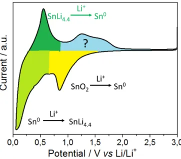
This questioned the origin of the extra capacity, which is not fully answered to date. The electrochemical performance of SnO2 for LiBs needs to be understood first, Figure 17.
Figure 17: Typical cyclic voltammetry profile showing the lithiation (yellow, green) and delithiation (dark green, blue) regions when nano SnO2 is cycled as a positive electrode versus lithium metal.
The conversion of SnO2 towards metallic Sn during initial lithiation causes extreme structural and volume changes (see also Equation 14). During further lithiation, up to 4.4 mol of lithium-ions are stored in the metallic Sn at low potentials (see Equation 13) and this reaction is considered fully reversible. There has been considerable disagreement regarding the reversibility
35 of the conversion process shown (back reaction towards Sn4+); some researchers suggest this reaction is irreversible (i.e. Sn remains in its metallic state) [103-105], whilst other researchers claim it is (partly) reversible (Sn0→Sn2+/4+) [106-108]. As shown in Figure 17, there is clearly additional electrochemical activity in the range 0.8 to 2.0 V vs. Li/Li+. This potential region has been investigated further by many groups to date (blue area in Figure 17). In an attempt to show the reversible formation of Sn4+, ex-situ X-ray photoelectron spectroscopy (XPS) measurements [107, 109] and ex-situ high resolution-transmission electron microscopy (HR-TEM) studies [109, 110] were used after the first delithiation step at ca. 3.0 V vs. Li/Li+. Conversely, Lee et al. suggested that the origin of this increased capacity could be mainly found in the electrochemical activity of LiOH/LiH/LiO2 [111]; such species were also believed to be responsible for the additional storage capacities observed for RuO2 (generated due to the presence of H2O which led to electrochemically active LiOH in the sample) [112].
Therefore, a convincing comprehensive proof of a reversible conversion reaction is still missing to date (although, there are many pieces of evidence).
36
Pseudocapacitive Battery Materials
1.5
Pseudocapacitive battery materials can be seen as hybrid electrode materials, as they combine the attributes of supercapacitor and battery materials. There are many extrinsic oxide supercapacitor materials (e.g. TiO2, VO2, layered titanate), which show battery-like behaviour for the bulk and increasing oxide supercapacitor-like behaviour with increasing surface area. For low surface area and well defined electrode materials made from suitable candidates, the insertion process occurs at defined potentials vs. Li/Li+ (Nernst behaviour, Equation 3); however, for nano-sized versions of the same materials, these potentials can vary considerably [113]. In Figure 18, the charge storage profile for potentiodynamic and galvanostatic electrochemical testing (for a negative electrode) is presented. For bulk electrode materials, the diffusion-limited (battery-like) insertion process is potential dependent for each material, whereas for nano-sized high surface area electrode materials, the charge is stored by surface effects (oxide supercapacitor-like) which results in potential semi-dependent charge storage [23].
The surface effects can be defined as a mixture of physical double-layers and pseudocapacitive fast Faradaic surface reactions [15]. For the pseudocapacitive process, the amount of charge
(ΔQ) from Faradaic charge transfer processes depends on the change in applied potential (ΔE). The derivative d(ΔQ)/d(ΔE) is equivalent to capacitance, and therefore the amount of stored
charge is “linearly” proportional to the applied potential [114]. As batteries show relatively high energy density, and oxide supercapacitors tend to show high power performance, nano-sizing known LiB electrode materials may be one solution for high power and high energy LiBs.
37
Figure 18: Comparison of the electrochemical manifestation of different charge storage mechanisms for potentiodynamic and galvanostatic measurements. The bulk negative electrode material stores the charge via lithium-ion insertion. A drastic decrease of particle size results in a shift to oxide supercapacitor-like behaviour (more stored charge via surface effects) [115].
Overall, one important goal of research is the marrying of the positive attributes of batteries (e.g. high capacity and energy density) with those of oxide supercapacitors (e.g. high power density). Metal oxides (such as titanates [24], Nb2O5 [116], vanadium oxides [117-119], RuO2 [120] etc.) have been actively investigated as candidate materials for such a purpose, as they have been shown to store charge through lithium-ion insertion (battery-like), as well as fast Faradic reactions on the surface of the materials (pseudocapacitance and Helmholtz double-layer capacitance).
38 1.5.1 Pseudocapacitance Insertion – Impact of Surface Area and Defects
High power nano-sized insertion materials often show increased defects on the surface and within the crystal due to the very small particle size. Such defects drastically influence the de-/lithiation performance and processes by shifting the thermodynamics and improving the kinetics.
Okubo et al. investigated various nano-crystalline LCO materials for LiBs and could see a large impact of the particle size and surface area on the electrochemical performance [121]. With increasing surface area (decreasing crystallite size), the stored charge decreased (which is similar to the idea of supercapacitors and batteries, where power and energy are inversely related). The slope of the discharge curve of the bulk materials was more rectangular (Figure 19a), meaning LCO undergoes a phase transformation during a redox reaction. With increasing surface area, there was increased charge storage via surface effects, which contributed to a more slope-like discharge curve. The site energy for intercalated lithium-ions is expected to take on a range of values due to the structural disorder for the layers near the surface (Figure 19b), which can also include a higher number of defects and larger inter-layer spacing in the surface layers.
As a result of the higher number of lithium-ion sites near the surface, the power performance (electrochemical performance at higher rates) was superior for 17 nm crystals compared to bulk 200 nm crystals [23, 121]. This was a landmark report, demonstrating the benefits of nano-sizing towards better power performance.
39
Figure 19: (a) Crystallite size dependence of the second discharge curve for LCO with various crystallite sizes. (b) Expected discharge curve for nano-crystalline LCO. The inset shows the structures within the particle together with the dispersed distribution of the site energy (modified taken from [121]).
Amorphous insertion electrode materials have been increasingly considered as possible high energy and high power electrode materials for lithium-ion and sodium-ion batteries [122], either for the negative [123-125] or the positive electrode [126, 127]. Interestingly, for the negative electrode side, it was possible to use materials such as V2O5 [123, 125] and Li4Ti5O12 [124] in the potential range of 0.05 to 3.0 V vs. Li/Li+. For each of these reports, the enhanced
40 electrochemical performance was explained to be due to higher ionic diffusion (larger access of lithium-ions from the electrolyte into the host and opening of diffusion pathways) in the amorphous phase compared to the crystalline counterpart. Moreover, Oh et al. observed that a wider operational potential window was likely due to a wider variety of electrochemically non-equivalent lithium-ion storage sites; vacant lattice sites can provide both cation and anion vacancies, whilst void spaces, cluster gaps or interstitial sites can also be present in this regard [125]. For similar materials (surface areas of 80 m2 g⁻1 [123] and 15 m2 g⁻1 [125] for a V2O5
aerogel), the shape of potentiodynamic and galvanostatic data plots can be described as a mixture of battery-like and oxide supercapacitor-like behaviour [123-125].
1.5.2 Niobium Pentoxide for High Power LiBs
Niobium pentoxide (Nb2O5) is an ideal high power electrode material in LiBs, as it is relatively inexpensive, environmentally benign and stable in a wide range of temperature and pH conditions [116, 128, 129]. The lithium-ion insertion and extraction process for crystalline Nb2O5 can be described with: xLi+ + xe- + Nb2O5 ↔ LixNb2O5, where x ≤ 2 (corresponding to 200 mAh g⁻1). In comparison to Nb2O5 in LiBs, graphite electrodes can suffer from low power
density [52, 53]. The specific capacity of crystalline Nb2O5 (200 mAh g⁻1)is relatively modest
compared to other materials like lithium metal, Si, Sn, graphite (3860, 3572, 993, 372 mAh g⁻1
, respectively), but Nb2O5 has the potential to deliver high power densities due to its high rate performance (combination of lithium-ion intercalation and fast charge storage arising from surface effects), including charge/discharge times of only a few seconds [116, 128-130]. Density functional theory (DFT) analysis by Ganesh et al. showed that the defined high-rate intercalation pseudocapacitative behaviour in this material is due to local charge-transfer at all adsorption sites (leading to high energy), open channels that reduce the diffusion barrier for lithium-ions to
![Figure 3: Specific power versus specific energy for different energy storage devices (Ragone plot modified taken from [3, 5])](https://thumb-us.123doks.com/thumbv2/123dok_us/11109829.2998780/22.892.258.671.584.896/figure-specific-specific-different-storage-devices-ragone-modified.webp)
![Figure 4: Comparison of the different battery technologies in terms of volumetric and gravimetric energy density (modified taken from [6])](https://thumb-us.123doks.com/thumbv2/123dok_us/11109829.2998780/23.892.265.649.613.894/figure-comparison-different-battery-technologies-volumetric-gravimetric-modified.webp)

![Figure 25: Density, dielectric constant and ionic product of water at 30 MPa as a function of temperature (simplified scheme modified taken from [182])](https://thumb-us.123doks.com/thumbv2/123dok_us/11109829.2998780/65.892.238.727.468.798/figure-density-dielectric-constant-function-temperature-simplified-modified.webp)