Zhao, Jia (2015)
Engineering serine integrase-based synthetic gene circuits
for cellular memory and counting.
PhD thesis.
https://theses.gla.ac.uk/6911/
Copyright and moral rights for this work are retained by the author
A copy can be downloaded for personal non-commercial research or study,
without prior permission or charge
This work cannot be reproduced or quoted extensively from without first
obtaining permission in writing from the author
The content must not be changed in any way or sold commercially in any
format or medium without the formal permission of the author
When referring to this work, full bibliographic details including the author,
title, awarding institution and date of the thesis must be given
Enlighten: Theses
https://theses.gla.ac.uk/ [email protected]
Engineering Serine Integrase-based Synthetic Gene
Circuits for Cellular Memory and Counting
Jia Zhao
A thesis submitted in fulfilment of the requirements for the degree of
Doctor of Philosophy
Institute of Molecular, Cell and Systems Biology
College of Medical, Veterinary and Life Sciences
University of Glasgow
© Jia Zhao 2015
All Rights Reserved
Abstract
A cellular counting system based on synthetic gene circuits would enable complex biological programming and be used in many biotechnology applications. Although a variety of synthetic memory circuits have been constructed, basic modules that can be assembled into a counting system are lacking. This thesis focuses on engineering a binary counting module, which can alternate between two states in response to a single repeating input signal. The highly directional large serine bacteriophage integrases were utilised as the basis for the synthetic circuits constructed in this study. Integrases and their protein co-factors, the recombination directionality factor (RDF) can change the orientation of a specific DNA segment flanked by two recombination sites. Integrase alone switches the orientation in one direction, and this directionality is reversed by the addition of its corresponding RDF. The two orientations can be used to turn gene expression on and off, leading to distinct output states which can be thought of as representing a single binary digit (0 and 1) heritably stored in the DNA.
In this study, three different serine integrase-based synthetic gene circuits for cellular memory and counting were engineered and characterised. A set-reset latch was first constructed. By expressing ϕC31 integrase and co-expressing integrase with RDF Gp3 from two independent inducible systems, the orientation of the invertible DNA in the set-reset latch was inverted and restored respectively. This device demonstrated that ϕC31 integrase can successfully encode information into plasmid DNA. Next, a state-based latch was constructed, in which the gp3
gene was placed inside the invertible DNA segment to couple its transcriptional regulation to the circuit state. Integrase expression triggered by one input signal resulted in inversion of the invertible DNA, placing the gp3 gene in the correct orientation for transcription. Gp3 expression can then be triggered by another input signal to reverse the directionality of integrase, restoring the DNA back to its original configuration. By optimising the stoichiometry and kinetics of integrase and Gp3 expression, efficient switching of both multi-copy plasmid and single copy chromosomal DNA was achieved. Finally, the state-based latch was developed into a binary counting module by introducing a delay mechanism, in which gp3 transcription was inhibited by a state-based repressor during recombination requiring the absence of Gp3. Placing expression of gp3 under the control of the invertible DNA, allowed a single input signal controlling only integrase expression to switch the module between OFF (0) and ON (1). This is the first integrase-based module that generates different outputs in response to the same input signal and a fundamental step towards building a genetic binary counter with large counting capacity.
Table of Contents
Abstract ... 2 Table of Contents ... 3 List of Tables... 8 List of Figures ... 9 Acknowledgements ... 13 Author’s Declaration ... 14 Abbreviations ... 15 1 Introduction ... 161.1 Introduction to synthetic biology ... 16
1.1.1 Genetic parts, devices, and systems ... 16
1.1.2 Development of platform technologies ... 17
1.2 Synthetic gene circuits for cellular computation and memory... 18
1.2.1 Engineering genetic switches for memory ... 18
1.2.2 Engineering synthetic oscillators for temporal control ... 24
1.2.3 Engineering genetic logic gates for processing multiple signals ... 26
1.2.4 Engineering genetic counting systems and their development ... 30
1.3 Introduction to genetic recombination ... 35
1.3.1 Homologous recombination ... 36
1.3.2 Site-specific recombination ... 36
1.3.3 Transpositional recombination (Transposition) ... 37
1.4 Classification of site-specific recombinases: tyrosine vs. serine recombinases ... 38
1.4.1 Tyrosine recombinases ... 39
1.4.2 Serine recombinases ... 40
1.4.3 Biological function of site-specific recombinases ... 40
1.5 Integrases and their applications ... 41
1.5.1 Tyrosine integrases... 42
1.5.2 Applications of Tyrosine integrases ... 43
1.5.3 Serine integrases... 44
1.5.4 Applications of serine integrases ... 46
1.6 Synthetic biological devices based on recombinases ... 47
1.7 Aims of the study and thesis outline ... 48
2 Materials and Methods ... 52
2.1 Bacterial Strains ... 52
2.2.1 Chemicals ... 52
2.2.2 Buffer solutions ... 53
2.3 Antibiotics ... 54
2.4 Repressors and Inducers ... 54
2.5 Oligonucleotides ... 54
2.6 Custom DNA synthesis ... 59
2.7 Plasmids ... 59
2.8 Bacterial growth medium ... 64
2.9 Bacterial growth conditions ... 64
2.10 Generalised transduction in E.coli by bacteriophage P1 ... 64
2.10.1 Preparation of P1 lysates ... 64
2.10.2 P1 transduction ... 65
2.11 Preparation of competent cells and transformation. ... 65
2.11.1 Chemical transformation ... 65
2.11.2 Electroporation ... 66
2.12 Conjugation ... 67
2.13 Transposition ... 67
2.14 Plasmid DNA preparation ... 67
2.15 Gel Electrophoresis ... 67
2.15.1 Agarose gel electrophoresis ... 68
2.15.2 Denaturing polyacrylamide gel electrophoresis ... 68
2.16 Extraction of DNA from gels ... 68
2.16.1 Extraction of DNA from agarose gels ... 69
2.16.2 Extraction of DNA from polyacrylamide gels ... 69
2.17 Ethanol precipitation of DNA ... 69
2.18 Concentration measurement ... 70
2.19 Restriction endonuclease digestion of DNA ... 70
2.20 Ligation ... 70
2.21 Oligonucleotide insertion ... 70
2.22 Polymerase chain reaction (PCR) ... 70
2.23 TOPO TA cloning ... 71
2.24 Site-Directed mutagenesis ... 72
2.25 Sequencing ... 72
2.26 In vitro recombination reactions ... 72
2.27.1 Overnight induction ... 73
2.27.2 Pulsed induction ... 73
2.27.3 Time course of induction recombination ... 74
2.27.3.1 Continuous induction time course ... 74
2.27.3.2 Short-pulse induction time course ... 74
2.28 Cell fixation ... 75
2.29 Cell fluorescence measurement... 75
2.29.1 Typhoon Scanner ... 75
2.29.2 Blue light Transilluminator ... 75
2.29.3 Flow cytometry ... 75
2.29.4 Fluorescent microscopy ... 75
2.30 MacConkey assay... 76
2.31 Production of substrate containing attR and attL ... 76
2.32 Random library construction and selection ... 77
2.33 Quantification by Quantity One ... 77
3 Preliminary characterisation and testing of ϕC31 integrase inversion recombination system ... 78
3.1 Introduction ... 78
3.2 Investigation of the inversion reaction mediated by ϕC31 integrase in vitro ... 79
3.2.1 Effects of ϕC31 integrase and Gp3 concentrations on recombination efficiency in vitro ... 80
3.2.1.1 Reactions with substrate plasmid containing attB and attP ... 80
3.2.1.2 Reactions with substrate plasmid containing attR and attL sites ... 81
3.2.2 Effects of reaction times on recombination efficiency ... 83
3.3 Investigation of the inversion recombination mediated by ϕC31 integrase in vivo ... 85
3.3.1 Construction and characteristics of a tightly regulated ϕC31 integrase expression system ... 85
3.3.2 Inversion recombination reaction with high copy-number plasmid substrates in vivo ... 88
3.3.2.1 Investigations on the attB×attP inversion reaction with the substrate plasmid pZJ16off ... 88
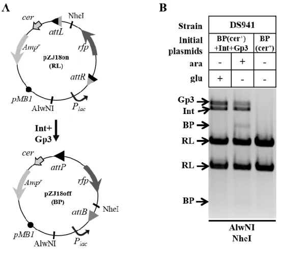
3.3.2.2 Investigations of attB×attP inversion reactions with substrate plasmid pZJ18off containing a cer recombination site ... 92
3.3.2.3 Investigations on the attR×attL inversion reaction with substrate plasmid pZJ18on containing a cer recombination site ... 95
3.3.2.4 Effects of Int expression levels on inversion reaction efficiency ... 97
3.3.3 Inversion recombination reaction with low copy-number plasmid substrates in vivo ... 100
3.3.3.1 Investigations on the inversion reaction mediated by Int with different
expression levels ... 100
3.3.3.2 Effects of reaction time on inversion reaction efficiency ... 103
3.4 Conclusion and discussion ... 104
4 Design and engineering of plasmid-borne memory devices ... 107
4.1 Introduction ... 107
4.2 Engineering of the genetic set-reset latch ... 108
4.2.1 Design and construction of the genetic set-reset latch ... 108
4.2.2 Investigation of the recombination efficiency with the set-reset latch ... 110
4.3 Engineering of the state-based latch (two-signal controlled system)... 114
4.3.1 Design and construction of the state-based latch ... 114
4.3.2 Characterisation of the state-based latch ... 120
4.3.2.1 Process of continuous time induction reaction ... 120
4.3.2.2 Reactions with different lengths of induction time ... 121
4.3.2.3 Reactions with different Int expression plasmids ... 122
4.3.2.4 Reactions in different strains ... 125
4.3.3 Further optimisation of the state-based latch by changing the expression levels of RDF gp3 ... 127
4.3.4 Reliability test of the optimised state-based latch under multicycle set-reset operation using two different input signals ... 131
4.3.5 Test of the state-based latch using Bxb1 integrase instead of ϕC31 integrase . 133 4.4 Engineering of the binary counting module (single-signal controlled system) ... 135
4.4.1 Developing the state-based latch into a binary counting module to be controlled efficiently in strain DS941 ... 135
4.4.2 Optimisation of the binary counting module by changing the expression levels of RDF gp3 ... 138
4.4.3 Characterisation of the optimised binary counting module to determine the optimal induction time ... 140
4.4.4 Reliability test of the binary counting module under multicycle on switch-off operation using a single input signal ... 144
4.5 Conclusion and discussion ... 148
4.5.1 Set-reset latch ... 149
4.5.2 State-based latch... 150
4.5.3 Binary counting module ... 151
5 The design and engineering of chromosomal memory devices ... 155
5.1 Introduction ... 155
5.2 Chromosomal delivery of memory devices using ISY100 transposition... 156
5.4 Investigation of factors affecting recombination efficiencies of chromosomal state-based latch ... 163 5.4.1 Effects of induction pulse length on recombination efficiencies ... 163 5.4.2 Effects of Int expression level and degradation rate on recombination efficiencies ... 165 5.5 Reliability test of the chromosomal state-based latch under multicycle set-reset operation ... 169 5.6 Test of the chromosomal devices with a single signal ... 171 5.7 Conclusion and discussion ... 177 5.7.1 Transposons as a tool to deliver a single copy substrate sequence into the E.coli
chromosome ... 177 5.7.2 Efficient and reliable recombination reaction with the chromosomal state-based latch (two signals controlled system) ... 178
5.7.3 Ways to improve the single-signal controlled systems ... 180 6 Final discussion ... 183 6.1 Primary data suggested ϕC31 integrase was a good candidate for construction of genetic devices ... 185 6.2 Plasmid-borne devices behaved efficiently ... 186 6.2.1 The set-reset latch proved that ϕC31 integrase could efficiently set and reset information in DNA ... 187 6.2.2 The state-based latch demonstrated that expression of RDF could be controlled by the DNA inversion state ... 187 6.2.3 The binary counting module realised the goal of altering outputs using a single repeating input signal ... 188 6.3 Making single copy memory devices ... 189 References ... 193
List of Tables
Table 1. 1 The classification and function of recombinases mentioned in this study ... 41
Table 2. 1 Bacterial Strains ... 52
Table 2. 2 Chemicals ... 52
Table 2. 3 Buffer Solutions ... 53
Table 2. 4 Antibiotics ... 54
Table 2. 5 Inducers and repressors ... 54
Table 2. 6 Oligonucleotides designed in this study ... 55
Table 2. 7 Plasmids used and constructed in this study ... 60
Table 3. 1 Int expression plasmids ... 98
Table 4. 1 Predicted promoters in Gp3 and GFP ... 120
Table 4. 2 Effect of gp3 RBS on reaction efficiencies ... 130
Table 4. 3 Induction times and recombination efficiencies for different memory devices ... 149
Table 5. 1 Int expression plasmids and recombination performance abtained ... 168
Table 5. 2 Recombination efficiencies of chromosomal devices controlled by a single signal ... 176
Table 5. 3 Comparison between the state-based latch and the rewritable recombinase addressable data module ... 179
List of Figures
Figure 1. 1 Synthetic switches based on transcriptional regulators. ... 20
Figure 1. 2 Synthetic switches based on recombinases. ... 23
Figure 1. 3 Synthetic oscillators. ... 25
Figure 1. 4 Conventional symbols and truth tables of basic logic gates. ... 26
Figure 1. 5 Synthetic logic gates based on transcriptional regulation and RNA regulation 28 Figure 1. 6 Synthetic logic gates based on recombinase ... 30
Figure 1. 7 Synthetic counters. ... 32
Figure 1. 8 A synthetic push-on push-off switch. ... 33
Figure 1. 9 A synthetic toggle flip-flop. ... 34
Figure 1. 10 Outcomes from site-specific recombination in circular molecules. ... 37
Figure 1. 11 Mechanism of recombination by tyrosine recombinases... 39
Figure 1. 12 Mechanism of recombination by serine recombinases. ... 40
Figure 1. 13 Mechanism of integration and excision catalysed by phage integrase. ... 42
Figure 1. 14 Recently proposed model of the integration reaction catalysed by serine integrases. ... 46
Figure 1. 15 A binary counter based on DNA inversion... 50
Figure 2. 1 Maps of synthetic plasmids. ... 59
Figure 2. 2 Flow diagram showing the overnight induction process. ... 73
Figure 2. 3 Flow diagram showing the short pulse induction process. ... 74
Figure 3. 1 Mechanism of ϕC31 integration, excision and inversion reaction. ... 79
Figure 3. 2 Expected change of substrate plasmids with the inversion recombination reaction. ... 80
Figure 3. 3 attB×attPin vitro reaction. ... 81
Figure 3. 4 attR×attLin vitro reaction. ... 82
Figure 3. 5 Kinetics of the in vitro inversion reaction. ... 84
Figure 3. 6 The MacConkey recombination assay. ... 86
Figure 3. 7 MacConkey recombination assay used to test the ϕC31 integrase expression system. ... 87
Figure 3. 8 Inversion reaction between attP and attB. ... 89
Figure 3. 9 Intramolecular and intermolecular recombination... 91
Figure 3. 10 Combination of integrase site-specific recombination and cer recombination to convert multimers to monomers... 93
Figure 3. 11 Comparison of the recombination between substrates without and with cer recombination site.. ... 94
Figure 3. 12 Inversion reaction between attR and attL. ... 96
Figure 3. 13 Process of changing the RBS sequence for Int. ... 98
Figure 3. 14 Effects of different Int expression levels on attB×attP and attR×attL recombination on high copy number substrate plasmids.. ... 99
Figure 3. 15 Effects of different Int expression levels on attB×attP and attR×attL recombination on low copy number substrate plasmids. ... 102
Figure 3. 16 Electrophoretic analysis of the attB×attP time course reaction. ... 103
Figure 4. 2 Electrophoretic analysis of the set-reset latch in the single directional reaction.. ... 111 Figure 4. 3 Electrophoretic analysis of the genetic set-reset latch in a full cycle of set-reset
reaction. ... 113 Figure 4. 4 Diagram showing the design principle of the state-based latch. ... 115 Figure 4. 5 Optimisation of the data storage element of the state-based latch... 117 Figure 4. 6 Electrophoretic analysis of the state-based latch under continuous induction
time course. ... 121 Figure 4. 7 Electrophoretic analysis of the state-based latch under pulsed induction time
course. ... 122 Figure 4. 8 Set and reset reaction of the state-based latch with different expression levels of Int. ... 124 Figure 4. 9 Performance of state-based latch in different strains. ... 126 Figure 4. 10 Process of seeking optimal Gp3 expression levels in state-based latch. ... 128 Figure 4. 11 Fluorescent analysis of cells containing substrate with different Gp3 RBSs
under set and reset reactions. ... 129 Figure 4. 12 Electrophoretic analysis of cells containing mutational state-based latch in a
full cycle of set-reset reaction. ... 130 Figure 4. 13 Five cycles of set-reset operation with the optimised state-based latch. ... 132 Figure 4. 14 Reset or Set operation with the state-based latch based on Bxb1 integrase. . 134 Figure 4. 15 The switch-on reaction of state-based latch in strain DS941.. ... 136 Figure 4. 16 The switch-on and switch-off reactions of the new device in strain DS941. 137 Figure 4. 17 Fluorescent analysis of cells containing substrate with different RBSs for Gp3
under set and reset reactions. ... 139 Figure 4. 18 Pulsed induction time course with the binary counting module by adding input signal after different preculture length.. ... 141 Figure 4. 19 Pulsed induction time course of the binary counting module... 143 Figure 4. 20 Multicycle operations with the binary counting module. ... 145 Figure 4. 21 Fluorescent analysis of cell population containing the binary counting module
in multicycle reactions. ... 147 Figure 4. 22 Expected performance of the binary counting module with single induction
pulse. ... 152 Figure 5. 1 Process of integrating the invertible substrate sequence into the chromosome.
... 158 Figure 5. 2 Methods used to check the recombination performance of the chromosomal
device. ... 161 Figure 5. 3 Flow cytometry analysis of the chromosomal state-based latch under pulsed
induction time course. ... 164 Figure 5. 4 Recombination efficiencies with different Int expression and degradation
conditions. ... 167 Figure 5. 5 Five cycles of set-reset operation with chromosomal state-based latch. ... 170 Figure 5. 6 Pulsed induction time course with chromosomal state-based latch (without time delay from TetR) using a single repeating signal... 173 Figure 5. 7 Pulsed induction time course with chromosomal binary counting module (with
Figure 5. 8 Recombination process with chromosomal single signal controlled module and the equation used to estimate switch-on and switch-off reaction efficiencies. ... 175 Figure 5. 9 Predicted performance of modules with different reaction efficiencies.. ... 182 Figure 6. 1 Summary of the results presented in previous result chapters ... 184 Figure 6. 2 A schematic diagram showing the hypothetical architecture of a two bit binary
This thesis is dedicated with all my love to my parents
Acknowledgements
I would like to thank so many people for supporting and helping me over the past four years. Special thanks go to my parents for encouraging me to pursue my dream and their unreserved support. Thank you to Qingnan who plays a fabulous role in my life, for his patience, understanding, and constant support. None of this could have happened without their love.
I would also like to thank those people who have contributed to the progress of my project. Great thanks go to Prof. Marshall Stark for his valuable advice and generously offering me lab resources; Dr. Femi Olorunniji for supplying me purified proteins and helping with the
in vitro assay. Thank you to Ms. Diane Vaughan for the training of flow cytometry, and Yanqing Song for the help on fluorescent microscope. Thank you to Dr. Martin Boocock, Dr. Alexandra Pokhilko, and Dr. Sally-Jane Rowland for all those interesting conversations in the office. I would like to thank people who have worked with me in Bower Building and helped me in many aspects: Dr. Mai-Britt Jensen, Miss Arlene McPherson, Dr. Steven Kane, Dr. Emanuele Conte and many others. Thank you to Prof. Gareth Jenkins and Prof. William Cushley for reviewing my work and providing help when I was in a difficult situation. Thank you to Prof. Geoffrey Baldwin and Prof. John Christie for examining my work and their suggestions for the future work.
Thank you to my amazing friend Dr. Menglin Cao for lighting my way whenever I felt confused. I am grateful to Dr. Christine Merrick for her help with my work and life, and her family for giving me a special memory of Christmas; Dr. Steph Holt for bringing me lots joy and her enormous contribution to the proofreading of this thesis. Thank you to Bin Jia for helpful discussion and suggestion. Special thanks go to Dr. Ben Zhang for giving me great inspiration and support, especially during my thesis writing, the toughest period in my life. My acknowledgements also go to my friends Min Hou, Carla Minguet, Johannes Mayer, Kevin Crawford, and Yujing Zhao whom I spent a wonderful time with in Glasgow.
Finally, I would like to express the great appreciation to my supervisors, Prof. Susan Rosser Dr. Sean Colloms, for giving me such a precious PhD experience. Thank you to Susan for offering me the opportunity to access to the cutting-edge research and work on such an exciting project, and her support and encouragement all along. Thank you to Sean for guiding me into the world of science, and his valuable suggestions and tremendous patience whenever I felt difficult to proceed. Thank you very much.
Author’s Declaration
“I declare that the research presented in this thesis is my own work except where stated and it has not been submitted for any other degree”.
Jia Zhao
Abbreviations
AHL acyl-homoserine lactone NRI~P phosphorylated NRI
APS ammonium persulphate PAGE polyacrylamide gel
electrophoresis
ara arabinose PCR polymerase chain reaction
aTc anhydrotetracycline RBS ribosome binding site
BAC bacterial artificial
chromosome RD recombinase domain
BP attB and attP RDF recombination directionality
factor
BSA bovine serum albumin RFP red fluorescent protein
CC coiled-coil motif RL attR and attL
CTD C-terminal DNA binding
domain RNA ribonucleic acid
DAP diaminopimelic acid RNAP RNA polymerase
DTT dithiothreitol SDS sodium dodecyl sulphate
dNTP deoxynucleotide
triphosphate SIMM
single invertase memory module
EDTA ethylenediaminetetraacetic
acid SKE SDS/protease K/EDTA
Fis factor for inversion
stimulation SSC side scatter
FSC forward scatter TAE Tris-acetate-EDTA
GFP green fluorescent protein taRNA transactivating noncoding RNA
IDB Integrase dilution buffer TBE Tris boric acid EDTA IHF integration host factor TEMED tetramethylethylenediamine
IPTG isopropyl
β-D-1-thiogalactopyranoside TF transcriptional factor IRB integrase reaction buffer Tris
2-Amino-2-hydroxymethyl-propane-1,3-diol
IS insertion sequence tRNA transfer RNA
L-Broth luria broth Xis excisionase
NTD N-terminal catalytic domain YFP yellow fluorescent protein
1 Introduction
1.1 Introduction to synthetic biology
Synthetic biology has emerged as a discipline combining biology with engineering principles over the past decade (Andrianantoandro et al., 2006; Cheng and Lu, 2012). With the rapid development of synthetic biology, several definitions have been used to describe this discipline. The commonly accepted definition of synthetic biology is that it “involves the design and construction of novel biological parts, devices and systems, and the redesign of existing natural biological systems for useful purposes” (Roberts et al., 2013). Synthetic biology utilises abstraction, modularization and standardization concepts from engineering to design biological systems, and builds up these systems using more efficient methods (such as DNA synthesis and DNA assembly). The goal of synthetic biology is to engineer the behaviours of organisms for many different applications, such as processing information and producing useful products (for instance biofuels, pharmaceuticals, and materials), meanwhile, deepening the understanding of biological processes.
1.1.1 Genetic parts, devices, and systems
One of the primary goals of synthetic biology is to construct novel biological systems from characterised parts. Parts can be assembled to create devices or modules, then multiple devices can be connected to form systems, and systems can be further developed into large networks and synthetic chromosomes (Cheng and Lu, 2012).
A growing number of parts have been characterised, such as promoters (Davis et al., 2011; Kelly et al., 2009), terminators (Chen et al., 2013), ribosome binding sites (RBSs, Salis et al., 2009), and protein degradation tags (Andersen et al., 1998; Cameron and Collins, 2014). These parts perform specific functions in various biological processes (transcription and translation of genes, post transcriptional processes, and degradation of proteins), and the behaviours of these processes can be regulated via tuning the parameters of corresponding parts (Arpino et al., 2013).
By using well-characterised parts, a number of higher-order devices have been constructed, such as switches and memory elements (Jerome Bonnet et al., 2012; Gardner et al., 2000; Ham and Lee, 2006), oscillators (Atkinson et al., 2003; Danino et al., 2010; Elowitz and
Leibler, 2000; Stricker et al., 2008), logic gates (Bonnet et al., 2013; Elowitz et al., 2002; Moon et al., 2012; Siuti et al., 2013; Wang et al., 2011), and counters (Friedland et al., 2009).
As the number of available synthetic devices has increased, more sophisticated systems have been created by assembling several devices together, or linking devices with cellular activities to execute useful human-defined functions. For example, a synthetic program containing a genetic multiplexer can be used to control the activation of two chemosensory pathways (Moon et al., 2011), and synthetic RNA regulatory systems linked to cell growth cytokine targets can be used to control cell proliferation (Chen et al., 2010).
1.1.2 Development of platform technologies
To achieve the goal of efficient construction of genetic systems, platform technologies need to be developed. The term “platform technology” refers to a suite of tools and methods which can be applied in the field of synthetic biology (Kitney and Freemont, 2012). Platform technologies include methods for part characterisation, host cells, DNA assembly, and web-based information systems. All these aspects are introduced in more detail below.
As mentioned in section 1.1.1, in order to reliably engineer devices or systems from genetic parts, it is necessary to characterise the properties and functional behaviours of parts (Canton
et al., 2008). To do this, standardized tools, techniques, and units of measurement are needed
to facilitate the characterisation of parts by independent groups (Kelly et al., 2009). Detailed knowledge of how different genetic parts and devices contribute to phenotypes of host cells, such as growth characteristics, differences between single and population cell behaviours, and metabolic burden, needs to be obtained to predict their performance in different cellular contexts.
As more complex systems need to be assembled from multiple genetic parts, DNA assembly is becoming a key platform technology for synthetic biology (Ellis et al., 2011). A number of techniques of DNA assembly have been developed, including 1) restriction and ligation-based methods, such as BioBricks™ (Knight, 2003) and Golden Gate (lab of Sylvestre Marillonnet, Icon Genetics GmbH, Germany); 2) homology-based approaches, such as sequence and ligation-independent cloning (Li and Elledge, 2007), Gibson Assembly (Gibson et al., 2009), and yeast in vivo DNA assembly (Shao et al., 2009), and 3)
site-specific recombination-based assembly, such as site-site-specific recombination-based tandem assembly (Colloms et al., 2013; Zhang et al., 2011) and Gateway (Kirchmaier et al., 2013).
Web-based information systems are another type of platform technology that will be necessary in scaling up the complexity of synthetic biology designs. Synthetic Biology Open Language is an example of such a system (Galdzicki et al., 2014). These systems should incorporate information about the part characterisations, host cells, DNA assembly methods, models, and software tools (Kitney and Freemont, 2012).
1.2 Synthetic gene circuits for cellular computation and
memory
As a main goal of synthetic biology, variations of synthetic gene circuits possessing human-defined functions have been constructed. These circuits endow cells with the ability to sense specific input signals, perform computations, commit to memory and respond with outputs, and have the potential to be used in a wide range of applications. For example, synthetic regulatory circuits can be used as intracellular sensing and control elements, providing novel strategies for disease diagnoses and therapies, and helping researchers understand more about biological systems in health and disease (Cheng and Lu, 2012).
This section focuses on the development of four types of synthetic gene circuits, which are genetic switches, oscillators, logic gates, and counters, named after their performances simulating electronic circuits. The limitation of current synthetic genetic counters and the significance of construction of an efficient counter are mainly discussed at the end of this section.
1.2.1 Engineering genetic switches for memory
In electrical engineering, a switch is used to control the current in an electric circuit. In a biological system, a genetic switch can be used to change the gene expression from one pattern to another in response to an environmental signal (Ptashne, 2004). Genetic switches have been found throughout natural systems, and widely used to support biotechnology applications (Bonnet and Endy, 2013). The simplest genetic switches are regulated promoters that can respond to specific signals to switch on and off gene expression. These promoters include the previously used promoter PL and PR (Elvin et al., 1990) and PLAC
al., 2014) and PBAD (Guzman et al., 1995), as well as some of their derivatives (Lutz and
Bujard, 1997).
Gene expression controlled by the regulated promoters mentioned above are transient. The state could only be maintained in the presence of the input signal, and the descendants of the cell have no memory that their ancestors had been exposed to any signal. Biological memory was defined as a sustained cellular response to a transient signal (Burrill and Silver, 2010). In practice, using regulated promoters that lack memory function as genetic switches has a number of limitations. For example, they cannot be used to detect transient signals, or control the expression of desired proteins after induction by a brief input. Compared to simple regulated promoters, the synthetic switches introduced in this section are more advanced in displaying memory. Typical examples of synthetic switches have been constructed by combining transcriptional regulation and feedback, or by using recombinases to record information into the DNA sequence.
An early example of a synthetic switch for memory is the toggle switch containing two repressible promoters that drive the expression of mutually inhibitory repressors (Fig. 1.1A, Gardner et al., 2000). In this toggle switch, each repressor negatively regulates the synthesis of the other repressor, thereby, creating two stable states. By addition of transient chemical or thermal induction, one repressor is inactivated selectively, switching the state of the device. This switch was demonstrated to retain state after removing the input signals.
In contrast to this early toggle switch, which only relied on negative feedback, subsequent switchable systems introduced positive feedback. In one example, a genetic switch containing both negative and positive feedback modules was constructed (Fig. 1.1B, Atkinson et al., 2003). The core element of this switch is a dual-input promoter Plac-glnAp2,
which is repressed by LacI (under the control of a constitutive promoter) and induced by NRI~P (phosphorylated form of glnG encoded nitrogen regulation protein NRI), and is set to drive the expression of NRI. NRI can induce its own expression from Plac-glnAp2 promoter.
There is a competition between the LacI and NRI~P on the Plac-glnAp2 promoter. Switching of
this circuit can be determined by controlling the level of effective LacI through varying the concentration of β-D-1-thiogalactopyranoside (IPTG), and is observed via the glutamine synthetase level produced from glnA gene (on the chromosome) driven by the toggle switch.
Later, a memory device in yeast based on autoregulatory transcriptional positive feedback was designed and constructed (Fig. 1.1C, Ajo-Franklin et al., 2007). The system consists of two elements, which are the “signal sensor” and the “autofeedback memory”. A signal induces the “signal sensor” to express a transcription factor which triggers the expression of the same transcription factor in the “autofeedback memory”. Then, the transcription factor starts to activate its own promoter even in the absence of input signal, resulting in memory. The fluorescent proteins RFP and YFP are used to label the “signal sensor” and the “autofeedback memory” respectively, and galactose is used as the input signal.
Figure 1. 1 Synthetic switches based on transcriptional regulators. (A) The toggle switch. Two repressible promoters are arranged to express their mutually acting repressors, resulting in bistable states in which only one of the two promoters is active at a given time. It can be flipped to the desired state using environmental inputs to disrupt the inhibition of the promoters. Adapted from Gardner et al. (2000). (B) The positive/negative feedback loop switch. One unit contains the dual-input promoter Plac-glnAp2 fused to glnG (gene encoding NRI).
The competition between the activator, NRI~P, and the repressor, LacI, on this promoter will determine the state of this device. The LacI is produced from a constitutive promoter in another unit, and its effect on the P lac-glnAp2 can be controlled by changing the concentration of IPTG. The state was observed through glutamine
synthetase level produced from glnA gene on the chromosome. Adapted from Atkinson et al. (2003). (C) The autoregulatory feedback loop switch. In the “signal sensor” unit, the expression of a transcriptional factor (TF) is controlled by an inducible promoter PGAL1/10. In the “autofeedback memory” unit, the transcriptional factor
can activate its own promoter, resulting in autoregulatory expression even in the absence of stimulus. Both present stimulus and previous exposure to stimulus will switch the states of the synthetic network from inactive to active. Adapted from Ajo-Franklin et al. (2007).
Another method to make genetic switches capable of memory is to encode memory into DNA sequence using the mechanism of site-specific recombination. Site-specific recombinases can recognise specific sequences (recombination sites) within a piece of DNA, catalyse recombination between these two sites, and flip the orientation of the intervening DNA sequence if the two sites are placed in inverted repeat (Stark et al., 1992). By using an inducible promoter to control the expression of a recombinase and change the substrate DNA conformation, information from the environmental or an intracellular signal can be written into the DNA circuit.
The early recombinase addressable switches were based on invertases, which are highly specialised in catalysing inversion recombination between sites in inverted repeat, while deletions between sites in direct repeat and recombination between sites on different molecules occur at very low frequency (van de Putte and Goosen, 1992). One such example is based on FimE inversion recombination system. Invertase FimE naturally inverts a DNA switch to control the expression of type I fimbriae in the fim system of Escherichia coli
(Holden et al., 2007). The synthetic switch was constructed by placing a constitutive promoter between inverted repeat recombination sites (IRRon and IRLon) for invertase FimE and a target gene was cloned outside of the recombination sites in an opposite orientation to the constitutive promoter (Fig. 1.2A). When the expression of invertase FimE is activated by adding inducer, the orientation of the promoter is flipped via FimE-catalysed DNA inversion, resulting in two new sites IRRoff and IRLoff and expression of the target gene. This
FimE inversion switch is a successful demonstration of recording information into a DNA sequence, and shows leak-less properties and persistence of state after removal of the inducer or recombinase input (Ham and Lee, 2006).
The same group constructed a more complex inversion switch based on two invertases FimB and Hin (Fig. 1.2B, Ham et al., 2008). The FimB invertase acts in the same fim system as FimE to control the expression of fimbriae in E. coli, but can invert the switch in both directions; from on to off and from off to on (Holden et al., 2007). The Hin invertase catalyses inversion recombination to control the expression of the flagellar gene H2 and the repressor gene of the flagellar gene H1 in the Hin system of Salmonella typhimurium (van de Putte and Goosen, 1992). The synthetic switch was constructed by integrating FimB and Hin recombination systems, in which two inversion switches were placed on the same DNA molecule in an overlapping manner. When the expressions of FimB and Hin are induced by addition of arabinose and anhydrotetracycline respectively in different orders, this device
switched to different states, and the states can be detected by PCR with chosen primers. This switch is the first artificial system that integrated two inversion systems into a single circuit and demonstrated the history dependent configuration of recombinase-based memory devices.
The recombinase FimE used in the earlier synthetic switch (Fig. 1.2A, Ham and Lee, 2006) inverts the DNA segment overwhelmingly from on (IRRon and IRLon) to off (IRRoff and IRLoff) orientation, whereas the FimB and Hin used in the latter switch (Fig. 1.2B, Ham et al., 2008) inverts the DNA segment in both directions (Holden et al., 2007; van de Putte and Goosen, 1992). There is not any controlled mechanism for these recombinases to invert and restore the state of target DNA sequence, and their recombination usually ends up with a mixture of two different states, which might limit their information storage capacity.
As an alternative to these invertases, the stability and capacity of the recombinase-based switches can be improved by using highly directional large serine integrases, which are able to invert and restore the orientation of a DNA segment under tight control. Two large serine integrases (from Streptomyces phage ϕC31 and from M. tuberculosis phage Bxb1) have been proved to catalyse efficient recombination between sites attP and attB and generate attR and
attL (Ghosh et al., 2003; Thorpe et al., 2000). Whereas, in the presence of a corresponding
phage encoded excisionase (Xis) or recombination directionality factor (RDF), the attP and
attB recombination is inhibited, and integrase catalyses recombination between attR and attL
to regenerate attP and attB (Khaleel et al., 2011; Ghosh et al., 2006).
The successful application of a serine integrase to create a synthetic switch was demonstrated by the rewritable recombinase addressable data module (Fig. 1.2C, Bonnet et al., 2012). In this device, a constitutive promoter was placed between recombination sites for Bxb1 integrase, facing towards one reporter gene (gfp) and away from another (rfp). The gene encoding Bxb1 integrase is under the control of a PLtet0-1 promoter so that its expression can
be controlled by addition of aTc. Separately, on a different plasmid, the RDF gene, gp47
together with Bxb1 integrase gene are under the control of a PBAD promoter so that their
expression can be activated by addition of arabinose. The unidirectional Bxb1 integrase catalyses inversion in one direction, flipping the promoter and changing reporter gene expression. With the assistance of the RDF gp47, Bxb1 integrase catalyses the reverse reaction, restoring the original reporter gene expression. It was demonstrated that this genetic switch flips repeatedly and reliably in response to alternate input signals aTc and arabinose
for multiple cycles. In addition, the switch is able to hold either state for approximately 100 cell doublings in the absence of any signal.
With the development of genetic circuits that can sense and remember environmental signals, some circuits have begun to be used for practical applications. One of the examples is the engineered E.coli which is able to detect and record an environment signal in the mammalian gut (Kotula et al., 2014). The memory device used in this system could be re-engineered to respond to disease-related signals (e.g. chemical signatures of inflammation, cancer, parasites, or environmental toxins in the gut) and produce diagnostic outputs (e.g. visual indicator) or therapeutic drugs (e.g. a specific antibacterial component), which may lead to the development of diagnostics and therapeutics.
Figure 1. 2 Synthetic switches based on recombinases. (A) The FimE inversion recombination switch. FimE recognises inverted repeat sites IRRon and IRLon, and inverts the intervening constitutive promoter to the correct
orientation for reporter gene expression. FimE expression is controlled by an inducible promoter. Adapted from Ham and Lee (2006). (B) The double inversion recombination switch. The inverted repeat sites with intervening constitutive promoter for FimB and Hin recombinase are placed in an overlapping manner. Several sets of primers (P1-P6) can be used to detect the order that FimB and Hin have been induced. Adapted from Ham et al. (2008). (C) The rewritable recombinase addressable data module. Bxb1 integrase recognises inverted repeat sites attP and attB, and recombines them to generate attL and attR sites. This inverts the intervening constitutive promoter, switching off expression of RFP and switching off expression of GFP. With the assistance of RDF gp47, Bxb1 integrase recognises inverted repeat sites attL and attR, and recombines them to generate attB and attP sites. This restores the intervening sequence to the original state. Adapted from Bonnet et al. (2012).
1.2.2 Engineering synthetic oscillators for temporal control
Oscillations are omnipresent in living systems, controlling processes such as metabolism, signalling pathways, cardiac and circadian pacemakers, and learning processes (Aubel and Fussenegger, 2010). Inspired by natural devices controlling the oscillation processes of living cells, many different synthetic oscillators have been successfully constructed. Around the same time as the first synthetic toggle switch was reported, the first synthetic oscillator was constructed by arranging three repressor-operator modules in a cyclic negative feedback loop (Fig. 1.3A, Elowitz and Leibler, 2000). In this network, the lactose operon repressor protein, LacI from E. coli, inhibits transcription of the tetracycline repressor gene, tetR from the tetracycline-resistance transposon Tn10, whose gene product represses the transcription λ repressor cI. Finally, λ CI inhibits the expression of LacI. This network produces fluctuating levels of each repressor protein. The fluctuating can be visualised using the reporter protein GFP that is driven by the target promoter of a specific repressor in the loop (e.g. PTET-gfp).
The oscillator introduced above was not robust and damped rapidly, which was thought to be a result of lack of positive feedback loops (Aubel and Fussenegger, 2010). The first synthetic oscillator combining positive and negative feedback loops was constructed a few years later (Fig. 1.3B, Atkinson et al., 2003). The core element of this switch is a dual-input promoter Plac-glnAp2, which is repressed by LacI and induced by NRI~P. The Plac-glnAp2
promoter is set to drive the expression of glnG, whose gene product, NRI, will be phosphorylated to form NRI~P. Production of NRI~P induces its own expression and that of LacI, until LacI builds up enough to suppress NRI~P expression. At this point, LacI expression starts falling, allowing NRI~P expression to start a new cycle. Oscillation is observed via the β-galactosidase level produced from the lactose operon driven by the LacI controlled Plac promoter.
With the rapid progress of synthetic gene circuits, a more precise, robust and tunable oscillator was constructed, which was also based on a dual-input promoter (Fig 1.3C, Stricker et al., 2008). In this network, a transcriptional repressor gene lacI, a transcriptional activator gene araC, and a reporter gene yemGFP are controlled by three identical copies of the dual-input promoter Plac/ara-1, which is repressed by LacI in the absence of IPTG and
activated by AraC in the presence of arabinose. In the presence of arabinose, the positive loop drives the expression of AraC, LacI, and YemGFP. While the LacI represses the
expression of these proteins in a negative feedback loop (in the absence of IPTG). The differential activity of the positive and negative feedback loops drives the oscillatory behaviour, and the period of the oscillator can be tuned by adjusting the levels of arabinose and IPTG. Cells containing this genetic circuit exhibits large-amplitude fluorescence oscillations and the oscillatory period is tunable.
However, none of the aforementioned oscillators can be synchronized, which is a limitation for the sensitivity and robustness of the dynamic response to external signals. This limitation Figure 1. 3 Synthetic oscillators. (A) The repressilator. A negative feedback cycle consists of three repressors: TetR, LacI and CI. Each of them represses its cognate promoter (PTET, PLAC and PCI) driving the expression of
the next repressor. A reporter gene is driven by PTET to indicate the state of the device. Adapted from Elowitz
and Leibler (2000). (B) The positive/negative feedback loop oscillator. One unit contains the dual-input P lac-glnAp2 promoter, which is activated by NRI~P and repressed by LacI, fused to glnG (the NRI encoding gene).
LacI is produced from a NRI inducible promoter in another unit, and its effect on promoter Plac-glnAp2 can be
synchronized by growing cells in medium with IPTG, that can inactivate LacI repressor. The oscillation is reported via the fluctuating β-galactosidase level affected by the PLAC driven lactose operon lacZYA. Adapted
from Atkinson et al. (2003). (C) The precise, robust and tunable oscillator. The dual-input promoter Plac/ara-1 is
activated by the AraC protein in the presence of arabinose and repressed by the LacI protein in the absence of IPTG. The expression of AraC, LacI and YemGFP is driven by three separate dual-input promoter Plac/ara-1. The
oscillation is reported via the YemGFP output. Adapted from Stricker et al. (2008). (D) The synchronized oscillator. The expression of LuxI protein, AiiA repressor, and YemGFP are driven by the PluxI promoter in
three separate transcriptional modules. The expression of LuxR is driven by the constitutive promoter PluxR.
LuxI enzymatically produces the small molecular AHL, which can bind to the LuxR protein to activate the promoter PluxI in a positive feedback loop, or be degraded by AiiA in a negative feedback loop. The AHL can
diffuse outside of the cell membrane and into neighbouring cells, which is the core factor for the synchronized oscillation. Adapted from Danino et al. (2010).
was overcome by a synchronized bacterial oscillator. This oscillator coupled the oscillatory network to a mechanism of quorum sensing system to enable population synchronization of oscillation (Fig. 1.3D, Danino et al., 2010). The expression of LuxI (a synthase that produces acyl-homoserine lactone, AHL), AiiA (a quorum-quenching component that mediates AHL degradation), and reporter YemGFP are under the control of the PluxI promoter, which is
induced by the signal molecule AHL bound to the LuxR regulatory protein (AHL-LuxR). The expression of LuxR is driven by the constitutive promoter PluxR. AHL, a core component
of the quorum sensing, can diffuse across the cell membrane and mediate intercellular communication. The combination of a positive feedback loop (LuxR–AHL complex actives the transcription of PluxI) and a negative feedback loop (AiiA negatively regulates the
transcription of PluxI by catalysing degradation of AHL) results in the synchronized
oscillation of cell populations at a critical cell density.
The oscillators discussed so far are completely independent from host metabolisms. The “metabolator” device coupled oscillation to glycolytic flux using the signalling metabolite acetyl phosphate, and demonstrated the possibility of using metabolic flux to control network oscillation (Fung et al., 2005). In addition, a recent work has demonstrated the functionality of a circadian oscillator in E. coli, a gut bacterium without its own native circadian rhythm. The oscillator system was transplanted from the autotrophic cyanobacteria synechococcus elongatus, and displayed a period that matched the geophysical day-night cycle. It can potentially be used in automated daily drug delivery, circadian control in industrial microbial process, and treatment of circadian rhythm disorders (Chen et al., 2015).
1.2.3 Engineering genetic logic gates for processing multiple
signals
In some cases, it is desirable to take actions or make decisions based on multiple intracellular or environmental inputs. To fulfill this requirement, synthetic logic gates were constructed that can give specific phenotype in response to multiple signals. The most basic logic gates are defined by conventional symbols and their performances are represented using corresponding truth tables (Fig. 1.4). Examples of logic gates constructed with protein-based transcriptional regulators, RNA-based post-transcriptional regulators, and site-specific recombinases are introduced in this section.
Early genetic logic gates were constructed with protein-based transcriptional regulators (Elowitz et al., 2002). These networks consist of three natural transcriptional regulators LacI, TetR, and λ CI, as well as promoters that produce different responses when assembled in different configurations. The binding state of LacI and TetR can be changed with inducers, IPTG and aTc, respectively. Thus, these two inducers are used as the input signals to stimulate the networks to display different logical behaviours depending on the different arrangements of promoters and transcriptional regulators. As an example, the logic circuits showed in Figure 1.5A acts as N-IMPLY in a lacI-E. coli strain, producing GFP only in the
absence of IPTG and in the presence of aTc.
Figure 1. 4 Conventional symbols and truth tables of basic logic gates. When the combination of input signals leads to the state change of the gate the value is defined as “1”. If not the value is “0”.
Another approach to control the regulatory logic of gene expression is through RNA regulators. One such example was based on synthetic ribozymes (Fig. 1.5B, Win and Smolke, 2008). By coupling a ribozyme to the 3’ untranslated region of a target gene, the ribozyme self-cleavage (active state of ribozyme) can inactivate the transcript and lower the gene expression. The synthetic ribozyme switch has three functional modules (actuator, sensor and transmitter), in which the “actuator” and “sensor” modules are connected by the “transmitter” module. When an input molecule binds to the sensor, the ribozyme’s self-cleavage activity is changed and therefore influences the expression of the target gene. The synthetic ribozyme behaves like a single-input buffer or an inverter that is inactivated or activated in the presence of input, respectively, increasing or decreasing gene expression, respectively. When using two ribozymes to control transcription, the output is high only when both ribozymes are in their inactive states. By assembling different functional synthetic ribozymes in different combinations, the engineered devices can behave as AND, NOR, NAND, and OR logic gates. For example, the AND gate shown in Figure 1.5B consists of two single input buffers, which produces gene product only in the presence of both inputs A and B.
Figure 1. 5 Synthetic logic gates based on transcriptional regulation and RNA regulation. (A) N-IMPLY gate (truth table on the right) based on transcriptional regulation. The expressions of LacI, TetR, λ CI and reporter GFP are controlled by PT, PL2, Pλ promoters respectively, and these promoters are repressed by TetR,
LacI and λ CI, correspondingly. In a lacI- strain, this device induces the expression of GFP only in the absence
of IPTG and in the presence of aTc. Adapted from Elowitz et al. (2002). (B) The AND gate based on RNA regulation. Each synthetic ribozyme containing actuator, sensor and transmitter modules functions as a single-input buffer that converts the single-input signal to increased gene expression output. Only in the presence of both inputs A and B, these two ribozymes are inactive, allowing production from the gene upstream of the device. Adapted from Win and Smolke (2008).
The logic gates described above depend on continuous presence of inputs to maintain their correct outputs, which have no memory of inputs. The development of genetic logic gates may require cellular memory, and this was realised in some recently constructed devices. The recombinase-based logic gates can logically convert transient chemical inputs into permanent changes in DNA architecture, implementing devices capable of memory (Bonnet
et al., 2013; Siuti et al., 2013). The recombinase-based logic gates perform their function by expressing two orthogonal recombinases from different inducible promoters and inverting the DNA sequence between two pairs of recombination sites. More details of the recombinases-based logic gates are introduced below.
Siuti et al. (2013) engineered two-input logic gates using Bxb1 integrase and ϕC31 integrase to act on DNA segments containing gene regulatory elements (promoters and terminators) and output genes. For example, an AND gate shown in Figure 1.6A consists of an inverted promoter and an inverted rfp gene surrounded by ϕC31 and Bxb1 recognition sites, respectively. RFP expression can occur only after the expression of ϕC31 and Bxb1 are activated by both input signals, and the inversion of both segments.
Independently, Bonnet et al. (Bonnet et al., 2013) assembled recombinase-based logic gates, where using Bxb1 and TP901-1 integrases to control the gene regulatory elements, the majority of which were asymmetric terminators that disrupt RNA polymerase flow in only one of two possible orientations. For example, in the AND gate shown in Figure 1.6B, the logic-gate operation consists of two unidirectional terminators flanked by either Bxb1 or TP901-1 recognition sites, and located between a promoter and a reporter gene. GFP expression can occur only after the expression of Bxb1 and TP901-1 have been activated by both input signals, causing the inversion of both terminators. Logic gates constructed in this study were designed as three terminal devices that decoupled the logic-gate operation from both input (promoter upstream of the logic-gate operation) and output (reporter gene or other output gene), enabling simple tuning and reutilization (Bonnet et al., 2013). Overall, in both logic gate systems, the chemical input signals were processed logically into the permanent change of DNA state, leading to a stable change in gene expression.
As mentioned at the beginning of this section, these multiple-signal regulated devices would be useful in some practical applications. One example is a dual-promoter integrator constructed by Nissim and Bar-Ziv, which acts as a AND gate to more precisely and efficiently discriminate and kill cancer cells than using a single-promoter approach (Nissim and Bar-Ziv, 2010). This synthetic circuit uses two cancer-related promoters to control the expression of two fusion proteins. The fusion proteins form a transcription complex to activate the expression of an output gene (reporter gene or killer gene) regulated by its own synthetic dual-promoter. Thus, cell death is executed only when the combined activity of two cancer related promoters is high.
1.2.4 Engineering genetic counting systems and their development
Natural systems utilise counting mechanism to measure the age of biological materials, such as the shortening of telomere would ultimately lead to cell death (Counter et al., 1992). Construction of genetic circuits that can count would enable a variety of biotechnology applications, such as executing cell death after a specified number of cell divisions, monitoring of aging, and recording number of environmental events (Smolke, 2009). However, engineering such device has had limited success, and only two synthetic counting systems have been constructed until now (Friedland et al., 2009).
Figure 1. 6 Synthetic logic gates based on recombinases. (A) The AND gate based on flipping promoter and gene. Integrase Bxb1 and integrase ΦC31 expressions are under the control of two different regulated promoters, which are activated by two different input signals, respectively. After both input signals have been present, the expressed integrases recognise and recombine orthogonal sites and flip the promoter and gene to the same orientation, resulting in the expression of reporter protein RFP. Adapted from Siuti et al. (2013). (B) The AND gate based on flipping asymmetric terminators. Integrase BxbI and integrase TP901-1 expressions are under the control of two different regulated promoters, which are activated by two different input signals, respectively. After both input signals have been present, the expressed integrases recognise and recombine orthogonal sites and flip the terminators, allowing transcription to flow through and expressing the reporter protein GFP. Adapted from Bonnet et al. (2013)
One of these synthetic counters exploited delays in a transcriptional cascade with additional translational regulation (Fig. 1.7A). The transcription of each gene in a downstream cascade is stimulated by a bacterial phage RNA polymerase (RNAP) expressed from a gene (in the upstream cascade). For the translational regulation, a cis-repressor sequence between the RBS and transcription start codon is complementary to the RBS sequence and therefore represses translation. A transactivating noncoding RNA (taRNA) binds to the cis repressor, relieving RBS repression, allowing translation. The production of taRNA is driven by the arabinose inducible PBAD promoter. The first short pulse of arabinose activates the translation
of T7 RNAP and stimulates promoter PT7, resulting in transcription of T3 RNAP. After a
specific interval, the second pulse of arabinose activates the translation of T3 RNAP and stimulates transcription of gfp from promoter PT3. A significant increase of GFP signal can
be detected only after the third pulse of arabinose is delivered (Friedland et al., 2009).
The other synthetic counter was constructed using recombinases Flpe and Cre as information
recording tools (Fig. 1.7B). Phage P1 Cre recombinase (Austin et al., 1981) and Flpe
recombinase, an improved mutation of yeast Flp recombinase (Buchholz et al., 1998), catalyse reversible site-specific recombination between two identical sequences, loxP sites for Cre and FRT sites for Flpe. The inducible PBAD promoter, flpe gene and a terminator were
placed between inverted repeat recognition sites for Flpe recombinase, forming a Single
Invertase Memory Module (SIMM). This SIMM is arrayed with a Cre SIMM in tandem so that the expression of the upstream recombinase induced by an input pulse of arabinose flips the entire SIMM and inverts the promoter into the correct orientation for the next recombinase. In this way, the SIMM is set from one state to the other, storing one-bit information in the circuit. After adding two arabinose pulses, the promoter upstream of gfp
gene is placed in a correct orientation to drive the expression of GFP, and when the third arabinose pulse is delivered, a significant increase of GFP signal can be detected. If the inducible promoters are different, this circuit can be used to record three different input events in a specific order (Friedland et al., 2009).
Both counting circuits perform counting functions based on specific lengths of input pulse. The transcriptional-based counter had a faster response to pulses (efficient response occurred with pulse lengths of ~20 to 30 min and pulse intervals of 10 to 40 min), whereas inversion by recombinases took more time (efficient response occurred with pulse lengths and intervals range from 2 to 12 hours). They can be applied to count different events depending on the time scales and frequencies of events.
In comparing the transcriptional-based and the recombinase-based counters, the information encoded into the DNA sequence by site-specific recombination is not susceptible to perturbations, and the state can be maintained in DNA sequence even after cell death. The recombinase-based counting system would be a promising direction as long as this technology is proved to be reliable under more circumstances.
Despite the advantages of the recombinase-based counting system discussed above, several limitations with this system need to be addressed. First, the state of each recombinase-based bit can only be set but not reset. Thus, the number it can count is linearly proportional to the number of recombinases used. Second, the uncontrolled directionality of reaction catalysed by recombinases in this system leads to continual flipping and influence on stability. Third, only transient signals with specific time scale can be recorded and only the final state can be Figure 1. 7 Synthetic counters. (A) The counter based on transcriptional and translational regulation. The transcriptional regulatory cascade of this device has three nodes. The transcription of T7RNAP gene is driven by a constitutive promoter PLtet0-1, and its gene product drives transcription of the gene encoding T3 RNAP in
the second node. T3 RNAP ultimately drives transcription of gfp gene in the third node. All transcripts are cis-repressed with the same riboregulator sequence. The taRNA, driven by arabinose inducible PBAD promoter,
binds to cis repressor to relieve its repression. An increase of GFP signal can be detected after three pulses of arabinose have been delivered. (B) The counter based on recombinases Flpe and Cre. This device contains two
Single Invertase Memory Modules (SIMMs) that are arrayed in a cascade. Each module consists of inverted repeat recombination sites flanking its own recombinase encoding gene and an inverted inducible promoter PBAD. The first time the device receives a short pulse of input signal, the Flpe recombinase in the upstream
module is expressed, which can flip the DNA sequence between sites FRTf and the FRTr. This flipping places
the promoter in the correct orientation for expressing Cre recombinase gene in the next module, the flpe gene
is no longer expressed and the cascade advances by one step. The second pulse of input signal drives expression of Cre recombinase and flips the DNA sequence between loxPfand loxPr. This places the promoter in the
correct orientation for driving expression of GFP and stops expression of Cre. After three input pulses, an increase of GFP signal can be detected. Both figures are adapted from Friedland et al. (2009).
reported by this circuit, limiting its use in recording events with different time scales and frequencies.
In consideration of these limitations, two different synthetic circuits have been proposed and constructed, which have the potential to be developed into counters. One such example is a push-on push-off switch, which can generate two distinct outputs in response to the same input signal (Fig. 1.8, Lou et al., 2010). This device rationally coupled a bistable switch memory module and a NOR gate. The memory module consists of two mutually repressed repressors λ CI and CI434 (encoded by the cI434 gene from phage 434). The transcription of cI and cI434 genes are controlled by PRM and PR promoters, which are repressed by CI434
and λ CI in turn. Reporter proteins RFP and GFP are expressed from promoters PRM and PR,
respectively. In the NOR gate, the transcription of cIind-(a mutant of cI whose gene product
cannot be degraded by RecA protease) is controlled by the regulated promoter PNOR, which
is repressed by both LacI and LexA repressors. If either LacI or LexA is in an ON state, the output CIind- from PNOR is OFF. UV irradiation activates RecA protease to specifically
degrade CI434, CI, and LexA, but not LacI and CIind- (Lou et al., 2010).
When the initial state of this device is “OFF” (RFP OFF), only PR promoter is activated and
this device expresses GFP and CI434. With the first UV pulse, LexA and CI434 are degraded by RecA and the expression of CIind- is activated from the NOR gate, resulting in the
activation of PRM and inhibition of PR, and pushing the memory module to “ON” (RFP ON)
Figure 1. 8A synthetic push-on push-off switch. This device consists of two modules: the memory module and the NOR gate module. In the memory module, two promoters (PRM and PR) drive the expression of their
mutual repressors (CI and CI434). In the NOR gate, cIind- is under the control of a regulated promoter, which
can be repressed by either LexA or LacI. LexA is constitutively expressed in the cell. The LacI expressed from the memory module and the CIind- expressed from the gate are two interconnecting parts that connect these two
modules. The UV irradiation activates RecA to specifically degrade CI434, CI, and LexA, but with no effect on LacI and CIind- (represented by the lightning). Adapted from Lou et al. (2010).


![[6 (Benzoyloxy) 1,4,5 trihydroxycyclohex 2 en 1 yl]methyl benzoate](data:image/gif;base64,R0lGODlhAQABAIAAAP///wAAACH5BAEAAAAALAAAAAABAAEAAAICRAEAOw==)