Technology (IJRASET)
Analysis and Simulation of Current Transformer
Aalakh Devari1, Pritam Thomke2, Devendra Sutar3
1Electronics and Telecommunication Dept., Goa College of Engineering, Farmagudi, Ponda Goa, India- 403401
2Electronics and Telecommunication Dept., Goa College of Engineering, Farmagudi, Ponda Goa, India- 403401
3Research & Development Dept., Siemens Ltd., Verna Industrial Estate, Verna, Goa, India- 403722
Abstract: The purpose of this paper is to simulate the response of Current Transformer based on different burden resistor and Primary input Current. For simulation of Current Transformer, ltpice IV was used which is freeware of PSPICE. Current Transformer Equivalent circuit was thoroughly analyzed and practical data test laboratory results were used to verify the simulation results. Current Transformer is one of key aspects for better performance of protective system. The fundamental property of the Current Transformer is to transform the high primary current to low secondary current as per the turn’s ratio. Simulation of Current Transformer helps in learning the transient behavior for different burden values and primary current. Keywords: Current Transformer Saturation, magnetizing inductance, Burden Resistor, ltspice IV
I. INTRODUCTION
When short circuit fault occur in an electrical system, there will be high current flowing in the system that can cause, permanently damage to equipment. To avoid such damage protective system using relays and instrument Transformer is usually required. The basic inputs that relay need is low input current which is scaled down value of high primary current. This requirement is met using Current Transformer. The purpose of Current Transformer is basically to convert high primary current to low secondary current which suitable for correct operation of relays and to ensure safety of equipment followed by protection system.
The Construction of Current Transformer is similar to that of Voltage Transformer with difference of having few primary turns and high secondary turns wound on the iron core. Current Transformer is connected in series with System unlike Voltage Transformer. The magnetic field around the primary conductor is utilized by the Current Transformer to induce current to the secondary windings. This method of converting high primary to low secondary also provides high level of isolation between secondary circuit and primary circuit.
[image:2.612.56.483.440.725.2]II. CURRENT TRANSFORMER EQUIVALENT CIRCUIT
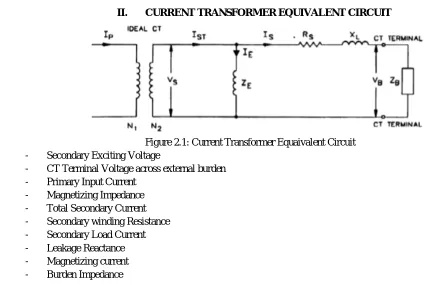
Figure 2.1: Current Transformer Equaivalent Circuit
Vs - Secondary Exciting Voltage
Vb - CT Terminal Voltage across external burden
Ip - Primary Input Current
Zm - Magnetizing Impedance
Ist - Total Secondary Current
Rs - Secondary winding Resistance
Is - Secondary Load Current
XL - Leakage Reactance
Im - Magnetizing current
Technology (IJRASET)
N1:N2 - CT turns ratio
The Current Transformer follows the equation given below
V = 4.44*N*Bm*Ac Eq. 1
Where Bm is the maximum Flux Density in Tesla (T) that can be supported by the core, Ac is the cross-sectional Area of the core and
N is Current Transformer Turns ratio.
The major disadvantage of using iron-cored Current Transformer is core saturation after which the current transformation from primary to secondary does not follow the turn’s ratio.
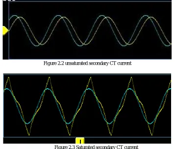
[image:3.612.128.487.236.540.2]Before Core saturates, the Current Transformer Secondary current is same in nature as the primary current with magnitude scaled down as per the turns ratio as shown in figure 2.2. Once the maximum flux that can be carried by the core is exceeded then the Current Transformer will not be able to reproduce the exact primary current. The secondary current will distorted as a consequence of core saturation as shown in figure 2.3.
[image:3.612.133.483.237.357.2]Figure 2.2 unsaturated secondary CT current
Figure 2.3 Saturated secondary CT current
Yellow colored waveform is the CT secondary Current and Blue colored waveform is the CT primary current. As can be seen in figure 2.3, after saturation secondary current waveform no longer follows the primary current waveforms.
The various reasons for saturation of current transformer are as follows;
1) High Primary Current
2) High Secondary Burden
3) Low turns ratio of CT
4) Small cross-sectional area of core
5) DC offset
Once the core saturates, the magnetizing inductance which conceptualized as parallel to the burden resistor is significantly lowered and hence the current is divided between burden resistor and Magnetizing inductance.
[image:3.612.136.481.383.530.2]Technology (IJRASET)
III. MAGNETIZING INDUCTANCE OF CURRENT TRANSFORMER
[image:4.612.156.453.128.208.2]We will discuss how the magnetizing current of CT affects accuracy and errors in a Current Transformer. Consider the simplified version of Current Transformer equivalent neglecting the leakage parameters.
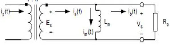
Figure 3.1 Simplified CT Equivalent
[3]The magnetizing current may be defind as the portion of primary current that satisfies the eddy and hysteresis current losses. As can be seen from simplified equivalent circuit of Current Transformer , Lm, (magnetizing inductance) and Burden resistor are in
shunt and hence current divides bewtween the two.
The magnetizing inductance depends on core parameters as given by the following equation
= Eq. 2
Where
Lm - Magnetizing Inductance (H)
N - Number of turns
A - Cross-section Area (m2)
µ0 - Permeability of free space
µr - core material incremental relative permeability
l - Mean path length of the core (m)
The main source of error in Current Transformer is the magnetizing current. Higher the magnetizing current higher is ratio and phase error in Current. The above equation shows that the magnetizing impedance is entirely dependent on core parameters. Core with lower relative incremental permeability will have lower magnetizing inductance and hence most of secondary current will be flowing through magnetizing component and output current through load will be less resulting high errors.
Incremental permeability is high is linear region and very low in saturation region and thus Current Transformer will produce high error in secondary current in saturation region. Thus it becomes important for an engineer to choose correct core and number of turns depending on the load.
IV. SIMULATION
In this project, ltspice IV is used to simulate the working of current Transformer based on equivalent circuit discussed above. Ltspice IV is a freeware high performance SPICE simulator Software. Current Transformer in Ltspice IV is simulated using Inductor having coupling between them. The coupling coefficient between the inductor is assumed to be 1 i.e. entire flux from primary couples to the secondary windings.
Simulated output is compared with physical Current Transformer, magnetic CT, having following details:
CT Turn’s Ratio : 2000
Burden Resistor : 470 ohms
Primary current : Varied from 0 to 30 A
Cross-section Area : 30 sq.mm
Mean Path Length : 11 mm
Technology (IJRASET)
Figure 3.1 Simulation of Current Transformer in Ltspice IV
Figure 3.1 Unsaturated Output of Simulation in Ltspice
[image:5.612.51.559.506.670.2]The above figure shows simulated output for 1 A input current producing 230 mV(rms) output across burden resistor. As expected output is clean sine wave without any distortion. Green color waveform is voltage across burden and white color waveform is primary input current.
Figure 3.1 Saturated Output of Simulation in Ltspice
Technology (IJRASET)
starts to saturate at input current of 20 A produciing output voltage of 4.54 V(rms).As can be seen from above figure, the secondary voltage across burden is slightly distorted (green waveform) as the CT approaches saturation.
The simulated CT has same core parameters and external burden resistor as the chosen physical CT. The Input signal is a current source which is varied from 0 to 20 A of current.
V. RESULTS
The results of simulated output and actual reading are shown in the table below
Primary Current (A) Reading (V) Simulated Output (V)
1 0.233 0.230
5 1.16 1.15
8 1.86 1.844
10 2.32 2.306
15 3.52 3.49
18 4.19 4.16
[image:6.612.56.558.154.272.2]20 4.66 4.54
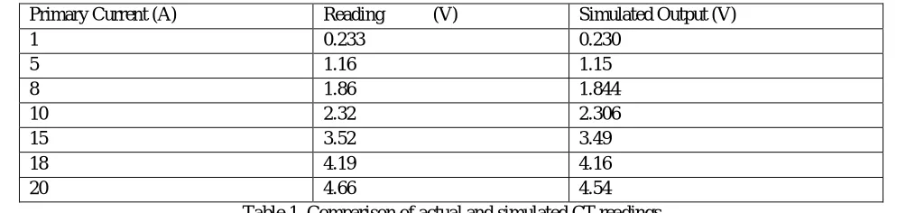
Table 1. Comparison of actual and simulated CT readings
The above table shows the actual reading of Current Transformer and simulated readings.
A. As can be observed, the simulated reading varies from actual reading by small margin. The following are the results:
1) The CT under test with 1 A of primary current produces output voltage 233 mV(rms) while the simulated CT in ltspice IV
produces 230.66 mV(rms)
2) The CT under test starts to saturate at 18.5 A of primary current whereas simulated model of CT starts to saturate at 20 A producing similar waveforms and output voltage
3) As can be seen from the comparison table, for all the input primary current simulated CT and CT under test produces similar secondary voltage across burden
VI. CONCLUSION AND DISCUSSION
The Current Transformer was simulated in ltspice, freeware software of SPICE. The parameters of simulated Current Transformer and physical Current Transformer were kept same and the output voltage for corresponding input current were noted. It was found that simulation produced the same output voltage as the physical CT for same set of input current and burden resistor with small constant error.
It was observed that start of saturation of simulated CT and physical CT is almost at same primary input current.
Model can be further improved by adding leakage resistance and inductance. Also the inter-winding capacitance can be added to the simulation model to get the exact behaviour of the Current Transformer.
VII. ACKNOWLEDGMENT
I am deeply indebted to my guides, Prof. Devendra Sutar, Professor, Department of Electronics and Telecommunication Engineering, and Mr. Pritam Thomke, Hardware Developer, Siemens Ltd, for allowing me to carry out this project under their supervision. They have given me confidence to take up this project and guided me to at times of difficulty.
I thank my teachers, who have taught enthusiastically at the Goa College of Engineering. I also thank Dr. Hassanali Gulamali Virani, (Head of the Department), Department of Electronics and Telecommunication Engineering and Dr. Vinayak N. Shet (Principal) Goa College of Engineering for allowing me to do this project and providing the necessary infrastucture .
I thank my parents, family members and well wishers, without whom this project would not have taken shape.
REFERENCES
[1] A Steady State Model for prediction of Amplitude and Phase Errors in Measuring Current Transformers, Tomasz Kutrowski, Wolfson Centre for Magnetics, School of Engineering, Cardiff University.
[2] The CT Behavior and its compatibility with Relay Protection, Ionut Ciprian BORASCU, U.P.B, Sci Bull, Series C, Vol.76, Iss. 3, 2014 [3] Mathematical Model for Current Transformer Based On Jiles-Atherton Theory and Saturation Detection Method, Xiang Li, University of Kentucky