Technology (IJRASET)
Active Harmonic Current Controlling Using
H-Infinitive Controller
S.Lakshmi Prasuna#1, V.Prathap Babu *2
#1
PG student, EEE Department, Gudlavalleru Engineering College, Gudlavalleru, AP, India *2Assistant professor, EEE Department, Gudlavalleru Engineering College, Gudlavalleru, AP, India
Abstract ─ In this paper cascaded current – voltage control technique proposed for DC-AC converters in distribution generation (DG) units. The main objective of the proposed controller is to improve the power quality by injecting a clean sinusoidal current to the grid even in the presence of local non-linear loads. This proposed controller consisting of inner voltage control loop and outer current control loop with both the controllers is designed by using H-infinitive repetitive control strategy. By this proposed controller, the THD value reduced and improved tracking performance. In order to verify the improvement of performance, the simulation results of the proposed controller compared with current control strategy in the conventional controller is done by using the MATLAB/Simulink.
Key words─ Distributed generation, H-infinity controller, power quality, Total harmonic distortion, cascaded current-voltage controller.
I. INTRODUCTION
Now a days, Renewable Energy Sources (RES) such as solar, wind are becoming more popular to generate power.This renewable energy based power generation generates DC power output. So an inverter is needed to convert DC energy from renewable energy sources into AC electrical energy. These renewable energy sources (RES) are connected to grid through grid connected PWM inverters which supply active and reactive powers to main grid. These inverters are either be connected in standalone (or) in grid connected mode. In case of grid connected mode, the output voltage of inverter should be same (or) it should be less than grid voltage and frequency should be same as that of grid frequency. In general, the loads connected to Distribution generation units are non-linear in nature. These can introduces power quality problems in the system. The harmonics occurred in the system due to the presence of non-linear loads. Due to this the Total Harmonic Distortion in the local load voltage and in the grid current is high. But it needs to be maintained low according to Industrial Regulation. Hence active and passive filtering methods have been developed to reduce these harmonics. But these are not favorable due to cost concerns. Several feedback current control methods used to obtain low THD value. But these are not favorable due to steady state fundamental current tracking errors. In order to obtain good performance and low THD value for the inverter local load voltage and grid current, H-infinitive Repetitive control technique is proposed. This H-infinity repetitive controller improves the power quality and tracking performance. It contains the inner voltage controller loop and outer current controller loop. The voltage controller is responsible for the power quality of the inverter local load voltage and power distribution and synchronization with the grid. The current controller is responsible for the power quality of the grid current, power exchanged with the grid and for the over current protection. When the inverter is connected to the grid, both the controllers are active and when the inverter is not connected to the grid then the inverter is under zero current reference. The inner voltage control loop takes the reference from the outer current control loop. The H-infinitive repetitive control strategy is used to design the controllers. This repetitive control technique is perfectly tracking the periodic signals and rejects the periodic disturbances in dynamic systems. The internal model acts as infinite dimensional by connecting a delay line into a feedback loop. This closed loop system helps to deal with larger number of harmonics.
II. CONVENTIONAL HARMONIC COMPENSATION METHOD
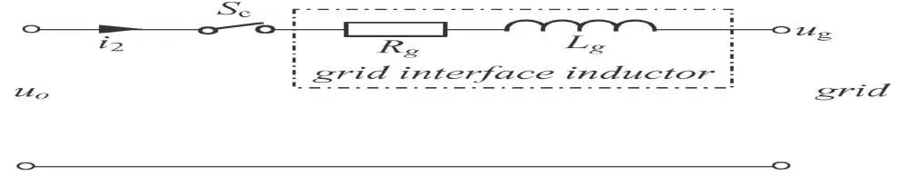
Fig:1 shows the configuration of single phase distribution generation(DG) unit connected to the grid through inverter bridge and coupling choke(Lf and Rf).It consists of grid interfacing inductor with a circuit breaker. Local load is connected at POC.These loads
Technology (IJRASET)
Fig:1 configuration of single phase distribution generation(DG) unit connected to the grid through inverter bridge and coupling choke(Lf and Rf).
Hence closed loop power control technique is used to achieve accurate power control performance in current controlled DG units. The current reference consists of two parts. The first one is the fundamental current reference can be determined in simple closed loop power control technique is
Iref-f = g1VPOCα + g2VPOCβ (1)
Where g1 and g2 are the gains which are adjustable and used to control real and reactive power respectively and VPOCα is the non
filtered POC voltage expressed in the α – β reference frame and VPOCβ is it’s orthogonal component.
The gains can be regulated as follows
g1 = (KP1+KI1/S) ( Pr e f - PD G) + Pref/E*2 (2)
g2 = (KP2+KI2/S) ( Qr e f - QD G) + Qref/E*2 (3)
Where KP1 and KP2 are proportional control parameters, KI1 and KI2 are integral control parameters, Pref and Qref are real and reactive
power references, E* is the nominal voltage magnitude of DG unit and τ is the time constant of first order low pass filter. PDG and QDG are measured DG power with low pass filtering as
PD G =
( )
(VPOCα I1α + VPOCβ I1β ) (4)
QD G =
( )
(VPOCβ I1α - VPOCα I1β ) (5)
Where I1αis the non-filtered DG current in α – β reference frame and I1β is its orthogonal component.
From equation (1), the fundamental current reference will be distorted if POC voltage has some ripples. In order to avoid this drawback, an improved proportional and resonant controller with two control branches is written asWc
Branch1:Power control Branch2:harmonic control
V*PWM = 2 ifwc s .(Iref-f – I1) + (KP +∑ , ,…, 2 ihwc s ).(Iref-h – I1)
Technology (IJRASET)
Branch1:Power control Branch2:harmonic control
= Gf(s) . (Iref-f – I1) + Gh(s) . (Iref-h – I1) (6)
The fundamental current reference in equation (1) is regulated by power control branch in equation (6) and harmonic components in Iref-f can be automatically filtered by using fundamental resonant controller in this branch. The harmonic current
reference Iref-h is regulated by harmonic control branch, where only harmonic resonant controllers used in this branch. In order to
avoid non characteristic harmonics exist in the system, a small proportional gain Kp is used to ensure superior harmonic current
tracking. The local load current (or) POC voltage is directly used as the input of the harmonic control branch. If harmonic reference current is set to zero, then the DG current is treated as ripple free in the harmonic control branch.
In summary harmonic current reference in equation (6) can have three options as follows
I local, Local nonlinear load compensation
Iref_h = -Vpoc/Rv, Feeder resonance voltage compensation
0, DG harmonic current rejection (7)
The output of harmonic control branch contains some fundamental components due to the proportional gain Kp when
the local load current (or) POC voltage are directly taken as input of harmonic control branch. Then these fundamental components make the interference with power control branch and produces fundamental current tracking with some steady state error.
III. PROPOSED CONTROL SCHEME
In the conventional harmonic compensation method, the stability can be low and it has some steady state error. In order to eliminate the impacts of steady-state fundamental current tracking errors in the DG units, H-infinity control technique can be used. In order to maintain the low THD value for the inverter local load voltage and grid current , the proposed controller consists of two loops; An inner voltage loop is used to regulate the inverter local load voltage and an outer current loop is used to regulate the grid current. This technique can deal with large number of harmonics, this leads to low harmonic distortion and improved tracking performance. It can deal with high disturbance rejection and gives high stability and good performance. According to the control theory of cascaded control, the dynamics of outer loop is designed to be slower than inner loop. The two loops are separately designed. The outer loop controller should be designed by taking the assumption that inner loop is in steady state; i.e, Uo = Uref .These two
controllers can be designed by using H-infinitive repetitive control because of high performance in reducing THD. The block diagram of hysteresis control is shown in figure 2. It consists of plant P and it has two inputs, one is external input w and that includes reference signal and disturbances, and another is manipulated variables u. Plant P has two outputs, one is error signal z that we want to minimize, and another one is measured variables v, that we use to control the system. v is used in K to calculate the manipulated variable u. Note that w,u,z and v are generally vectors , whereas P and K are matrices.
Fig.2.General block diagram of H∞ control scheme
Technology (IJRASET)
current controller loop. The voltage controller can be used to generate and dispatch power to the local load and to synchronize the inverter with grid. If the inverter is synchronized with grid then the voltage and frequency are easily determined by the grid. The current controller can be used for over current protection and it can exchange clean current with grid even in the presence of non-linear loads. Here the current controller is normally included in the drive circuits of inverter. The PLL’s can be used to determine the phase of the grid voltage, which is needed to generate Iref. In this H-infinity control, the output of current controller is added to
the grid voltage. This can be used for synchronization mechanism.
Fig.3.Proposed cascaded current-voltage controller for inverters where both adopt H∞ control strategy
IV. DESIGN OF VOLTAGE CONTROLLER
The voltage controller can be designed with H-infinity controller using repetitive control strategy. In this the amount of delay used in the internal model is equal to the period of the external signals.
A. State Space Model Of Plant PV
The control plant for voltage controller is shown in figure 4. It consists of an inverter bridge with PWM block and LC filter(Lf and
Rf).The PWM block and inverter bridge can be ignored while designing the controller because these can be designed by using
average voltage approach with the limits of DC link voltage. Then the average value of Uf over a sampling period is equal to Uv.
Fig.4.Control plant for inner voltage controller
Technology (IJRASET)
I2 and voltage reference Vref are taken as external input Wv = [ I2 Vref]T and Uv is taken as control input. Then the tracking error ev
nothing but output signal from plant is written as ev = Vref – Vo where Vo is the inverter local load voltage and Vo = Vc + Rd ( I1 – I2
).Then the state equation of the plant is written asn
Xv. = Av Xv + Bv1 Wv + Bv2 Uv (8)
and the output equation can be written as
Yv = Cv1 Xv + Dv1 Wv + Dv2 Uv (9)
Where
-(Rf + Rd) -1
Av = Lf Lf
1
Cf
Rd 1
Bv1 = Lf Bv2 = Lf
- 1
Cf
Cv1 = -Rd -1 Dv1 = Rd 1 Dv2 = 0
Then the plant transfer function is
Av Bv1 Bv2
Pv =
Cv1 Dv1 Dv2
B. Standard H∞ Problem Formulation
To make sure that this internal voltage loop is stable, it is formulated to minimize the H∞ norm of the transfer function TZv,Wv = Fl(
Pv,Cv) from Wv = [Uv Wv]T to Zv = [Zv1 Zv2]T. This can be done after opening the local positive feedback loop of internal model
and introducing the weighting parameters ξv and µv. The formulation of H∞ control problem for voltage controller is shown figure5.
Technology (IJRASET)
Then the closed loop system can be represented as
Zv = Pv Wv
Yv Uv
Uv = Cv Yv
Where Pv is the generalized plant and Cv is the voltage controller.
This generalized plant Pv consists of original plant with low pass filter Wv = Awv Bwv ,Which is the internal model of repetitive
control.
Cwv Dwv
Where ξv and µv are the weighting parameters and play a vital role in guaranteeing the stability of the system. Then the generalized
plant Pv is written as
Av 0 0 Bv1 Bv2
Bwv Cv1 Awv Bwv ξv Bwv Dv1 Bwv Dv2
Pv = 0 Dwv Cv1 Cwv Dwv ξv Dwv Dv1 Dwv Dv2
0 0 0 0 µv
Cv1 0 ξv Dv1 Dv2
(10)
By using the hinfsyn function in MATLAB , the controlled Cv can be found from the generalized plant Pv using H∞ control theory.
V. DESIGN OF CURRENT CONTROLLER
As said earlier, for the designing of the current controller, let us assume that the inner voltage is in steady state i.e, Uo = Uref. The
[image:7.612.128.498.298.434.2]figure 6 shows the control plant for the outer current loop controller. It consists of grid interface inductor. This controller also designed by using repetitive control theory like as voltage controller. The formulation of the H∞ control problem is same as voltage controller as shown in figure 5 but with a different plant Pi and subscript u is replaced with i.
Fig.6. Control plant for outer current controller
A. State Space Model Of Plant Pi
Here it is assume that Uo = Uref then Uo = Ug+Ui or Ui = Uo – Ug. Where Ui is the voltage drop across grid inductor. Here the same
[image:7.612.57.558.560.662.2]Technology (IJRASET)
important feature of current controller. For the design process, the Ui is considered as output.
Here the grid current i2 is taken as state variable and current reference Iref is taken as external input Wi = [Iref] and Ui is taken as
control input. The tracking error nothing but output signal from plant is taken as ei = Iref – I2.Then the state equation of the plant Pi is
Xi. = Ai Xi + Bi1 Wi + Bi2 Ui
And the output equation can be written as Yi = ei = Ci1 Xi + Di1 Wi + Di2 Ui
Where Ai = -Rg Bi1 = 0 Bi2 = 1 Ci1 = -1 Di1 = 1 Di2
Lg Lg
Then the transfer function of the plant Pi is
Ai Bi1 Bi2
Pi =
Ci1 Di1 Di2
B. Standard H∞ Problem Formulation
The formulation of H∞ problem for the current controller is same as voltage controller. Then the generalized plant can be written as
Ai 0 0 Bi1 Bi2
Bwi Ci1 Awi Bwi ξi Bi1 Di1 Bwi Di2
Pi = Dwi Ci1 Cwi Dwi ξi Dwi Di1 Dwi Di2
0 0 0 0 µi
Ci1 0 ξi Di1 Di2
(11)
The selection of weighting parameters ξi and µi and low pass filter Wv = Awi Bwi can be done same as voltage controller.
Cwi Dwi
By using the hinfsyn function in MATLAB , the controlled Ci can be found from the generalized plant Pi using H∞ control theory.
VI. DESIGN EXAMPLE
Technology (IJRASET)
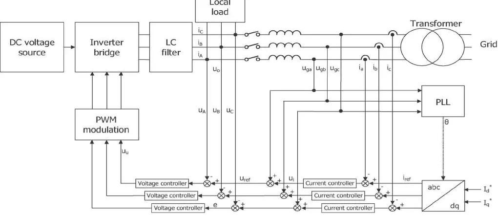
Fig.7.Block diagram for grid connected three phase inverter using the proposed strategy
The parameters of the inverter and grid are shown in table 1.In general the low voltage system has the more impact of noises and disturbances than high voltage system. Hence it is easily applied to inverters at high voltage and high power ratings.
TABLE 1: PARAMETERS OF THE INVERTER
Parameter Value Parameter Value
Lf 150µH Rf 0.045Ω
Lg 450µH Rg 0.135Ω
Cf 22µF Rd 1 Ω
A. Design of the H∞ voltage controller
For the parameters shown in table ,the weighting function and the weighting parameters chosen for frequency f = 50Hz are
Wv = −2555 2550
1 1 and ξv = 100 and µv = 1.85.Then the H ∞
voltage controller to minimize the H∞ norm can be written as
Cv(s) =
. ( . ∗ )
( )( . ∗ )
and it can be reduced to
Cv(s) = .
The performance can not be degraded after cancellation of nearest poles and zeros.
B. Design of the H∞ current controller
For the parameters shown in table ,the weighting function and the weighting parameters chosen for frequency f = 50Hz are
Wv = −2555 2550
1 1 and ξv = 100 and µv = 1.8.Then the H ∞
[image:9.612.123.482.395.453.2]Technology (IJRASET)
Ci(s) =
. ( )
( . ∗ )( )
The performance can not change after changing the factor (S+4.334*108) as 4.334*108 and reduced controller is
Ci(s) = .
VII. SIMULATION RESULTS
The H-infinitive controller was implemented in different compensation modes and these results are compared with the results of
conventional method to prove the reduction of harmonics.
1) Responses in DG harmonic current rejection mode: In this compensation mode the harmonic reference current Iref-h is taken as
zero i.e; Iref-h= 0.The parameters used in the simulation are shown in Table.2.In this real and reactive powers are set at 600W
[image:10.612.51.563.324.666.2]and 200VAR respectively. The performances occurred in the harmonic current rejection mode is shown in figures 8,9,10,11 and 12.By observing these performances the harmonics occurred in the dg current and grid current using conventional controller are 1.54% and 31.59% respectively. These harmonics are reduced in the dg current and grid current to 0.01% and 1.62% respectively by using H-infinitive controller.
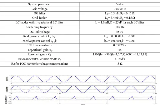
TABLE 2 :PARAMETERS OF THE SYSTEM
System parameter Value
Grid voltage 230/50Hz
DG filter Lf = 6.5mH,Rf = 0.15 Ω
Grid feeder Lg = 3.4mH,Rg = 0.15 Ω
LC ladder with five identical LC filter L = 1.0mH,C = 25µF for each LC filter
Switching frequency 10KHz
DC link voltage 550V
Real power control kp1,kI1 kp1 = 0.00001,kI1 = 0.001
Reactive power control kp2,kI2 kp2 = 0.00001,kI2 = 0.001
LPF time constant τ 0.0322Sec
Proportional gain Kp 48
Resonant gains Kih 1500(h=f);900(h=3,5,7,9);600(h=11,13,15)
Resonant controller band width ωc 4.1rad/s
Rv(for POC harmonic voltage compensation) 5 Ω
Technology (IJRASET)
Fig 9: POC voltage and fundamental reference current of DG unit during DG harmonic rejection mode in the conventional control method.
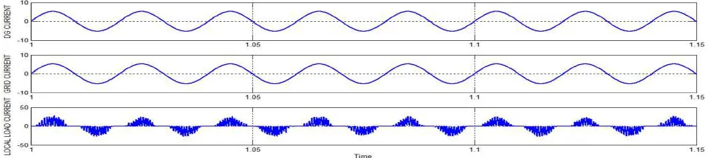
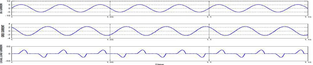
[image:11.612.80.551.557.672.2]Fig10: DG current, grid current and local load current of DG unit during DG harmonic rejection mode using H-infinitive controller
Fig 11: POC voltage and fundamental reference current of DG unit during DG harmonic rejection mode using H-infinitive controller.
Conventional controller H-infinitive controller
Technology (IJRASET)
[image:12.612.82.552.38.200.2](b)
Fig 12:THD in the DG harmonic rejection mode(a)DG current (b)Grid current
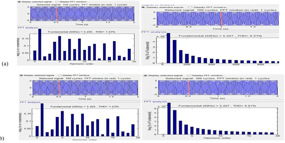
2) Responses in Local non-linear load compensation mode: In this compensation mode, the harmonic reference current is taken as
local load current i.e; Iref-h= Ilocal. The performances occurred in the local non-linear load compensation mode is shown in figures
[image:12.612.58.557.301.394.2]13,14,15,16 and 17.By observing these performances the harmonics occurred in the dg current and grid current using conventional controller are 1.53% and 1.53% respectively. These harmonics are reduced in the dg current and grid current to 0.01% and 0.01% respectively by using H-infinitive controller.
Fig 13: DG current, grid current and local load current of DG unit during local non-linear load compensation mode in the conventional control method.
Fig 14: POC voltage and fundamental reference current of DG unit during local non-linear load compensation mode in the conventional control method.
[image:12.612.58.558.434.537.2] [image:12.612.58.557.577.681.2]Technology (IJRASET)
Fig16: POC voltage and fundamental reference current of DG unit during local non-linear load compensation mode using H-infinitive controller.
Conventional controller H-infinitive controller
(a)
[image:13.612.70.558.251.496.2](b)
Fig 17:THD in the local non-linear load compensation mode (a)DG current (b)Grid current.
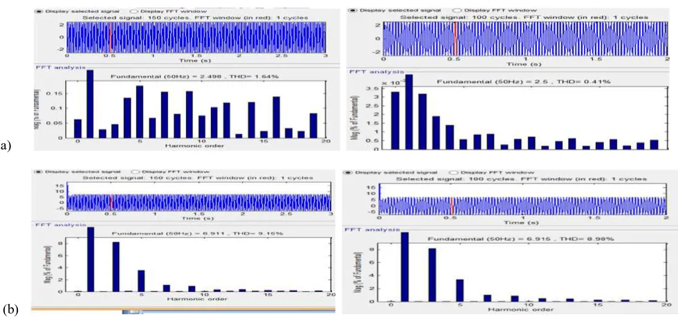
3) Responses in Feeder resonance voltage compensation mode: In this compensation mode, the harmonic reference current is
taken as Iref-h= -Vpoc/Rv. The performances occurred in the feeder resonance voltage compensation mode is shown in figures
18,19,20,21 and 22. By observing these performances the harmonics occurred in the dg current and grid current using conventional controller are 1.64% and 9.15% respectively. These harmonics are reduced in the dg current and grid current to 0.41% and 8.98% respectively by using H-infinitive controller.
Technology (IJRASET)
[image:14.612.57.559.99.163.2]conventional control method.
[image:14.612.53.560.210.289.2]Fig 19: POC voltage and fundamental reference current of DG unit during feeder resonance voltage compensation mode in the conventional control method.
Fig 20: DG current, grid current and local load current of DG unit during feeder resonance voltage compensation mode using H-infinitive controller.
Fig 21: POC voltage and fundamental reference current of DG unit during feeder resonance voltage compensation mode using H-infinitive controller.
Conventional controller H-infinitive controller
(a)
(b)
[image:14.612.50.562.334.402.2] [image:14.612.76.566.466.695.2]Technology (IJRASET)
VIII. CONCLUSION
In this paper, H-infinitive repetitive controller is used in the grid connected DG units. This proposed controller verifies the feasibility by comparing with the conventional method .The H-infinitive controller consists of inner voltage loop and outer current loop with its excellent performance in reducing THD of both inverter load voltage and grid current .This proposed controller guarantees the low THD value, high stability and it increases the tracking performance, is done by using the MATLAB/Simulink.
REFERENCES
[1] Jinwei He,Yun Wei Li, Frede Blaabjerg, and Xiongfei Wang,” Active Harmonic Filtering Using Current-Controlled, Grid-Connected DG Units With Closed-Loop Power Control”,IEEE TRANSACTIONS ON POWER ELECTRONICS, VOL. 29, NO. 2, FEBRUARY 2014
[2] Qing-Chang Zhong, and Tomas Hornik ,” Cascaded Current–Voltage Control to Improve the Power Quality for a Grid-Connected Inverter With a Local Load” IEEE TRANSACTIONS ON INDUSTRIAL ELECTRONICS, VOL. 60, NO. 4, APRIL 2013
[3] T. Hornik and Q.-C. Zhong, “H∞ repetitive voltage control of grid connected inverters with frequency adaptive mechanism,” IET Proc. Power Electron., vol. 3, no. 6, pp. 925–935, Nov. 2010.
[4] R. I. Bojoi, L. R. Limongi, D. Roiu, and A. Tenconi, “Enhanced power quality control strategy for single-phase inverters in distributed generation systems,” IEEE Trans. Power Electron., vol. 26, no. 3, pp. 798–806, Mar. 2011.
[5] George Weiss, Qing-Chang Zhong, Tim C. Green, and Jun Liang, “H∞ Repetitive Control of DC-AC Converters in Micro grids ” , IEEE TRANSACTIONS ON
POWER ELECTRONICS, VOL. 19, NO. 1, JANUARY 2004.
[6] Tomas Hornik and Qing-Chang Zhong, “A Current-Control Strategy for Voltage-Source Inverters in Microgrids Based on H∞ and Repetitive Control”, IEEE
TRANSACTIONS ON POWER ELECTRONICS, VOL. 26, NO. 3, MARCH 2011.
[7] F.Blaabjerg, Z.Chen, and B.S.Kjaer, “Power electronics as efficient interface in dispersed power generation systems”, IEEETrans.Power Electron., Vol.19, No.5, pp.1184-1194, Sep 2004.
[8] M.Supujitha Sukumar , R. Madhusudhan Rao,” Power Quality Improvement in Microgrids By Repetitive Cascaded Current -Voltage Control With Load Using Hybrid Voltage Source”, IJSRE Volume 2 Issue 11 November 2014 Page 2300.
[9] L.Asiminoaei,F.Blaabjerg,andS.Hansen,“Detectioniskey—Harmonic detection methods for active power filter applications,” IEEE. Ind. Appl. Mag., vol. 13, no. 4, pp. 22–33, Jul./Aug. 2007.
[10] C. Lascu, L. Asiminoaei, I. Boldea, and F. Blaabjerg, “High performance current controller for selective harmonic compensation in active power filters,” IEEE
Trans. Power Electron, vol. 22, no. 5, pp. 1826–1835, May 2007.
[11] C.Lascu,L.Asiminoaei,I.Boldea,and F. Blaabjerg,“ Frequency response analysis of current controllers for selective harmonic compensation in Active power
filters,”IEEETrans.PowerElectron,vol.56,no.2,pp.337– 347, Feb. 2009.
[12] T. Hornik and Q.-C. Zhong, “H∞ repetitive current controller for gridconnected inverters,” in Proc. 35th IEEE IECON, 2009, pp. 554–559.
[13] Q.-C. Zhong, J. Liang, G. Weiss, C. Feng, and T. Green, “H∞ control of the neutral point in 4-wire 3-phase DC–AC converters,” IEEE Trans. Ind. Electron., vol. 53, no. 5, pp. 1594–1602, Nov. 2006.
S.LAKSHMI PRASUNA Received her B.Tech degree in Electrical and Electronics Engineering from Malineni Lakshmaiah Engineering College, Singarayakonda, affiliated to JNTU, Kakinada in 2012. He is pursuing M.Tech in the department of Electrical and Electrical Engineering with specialization in Power Electronics and Electric Drives in Gudlavalleru Engineering College, Gudlavalleru, A.P, India. His research interests include Power Quality and Control.
V.PRATHAP BABU has received his B.Tech degree from Bonam venkata chalamayya Institute of Technology and Sciences under J.N.T.University, Hyderabad in the year 2007. M.Tech degree with the specialization of Power Systems from Pune University in the year 2010. At present he is working as an Assistant Professor in Gudlavalleru Engineering college, Gudlavalleru. His areas of interest are Electrical Machines,Power systems and Power Electronics.