6
I
January 2018
Performance Enhancement of Simple Vapour
Absorption System Using Loop Heat Pipes
Ankit Dwivedi1, R S Mishra2
1, 2
Dept. of Mechanical Engineering, Delhi Technological University, Delhi
Abstract: A Vapour Absorption Refrigeration System is able to use waste heat, which makes it very useful in the Energy Crisis. In this research work, as beginning a loop heat pipe (LHP) with different specifications are employed to re-use the heat that has been rejected in the widely used conventional condensers. The condensation after the generator occurs in as a flow condensation as it rejects heat to the evaporator of LHP. Hence by removing the conventional condenser or by reducing its size, it will drastically result in cost reductions. This research work finds that COP I increases by up to 80% due to the re-use of heat. Also due to the removal of the bulky anergy creating parts, the exergy losses are reduced and the COP II increases up to 30%. The size of the system reduces and the system becomes easy to operate.
I. INTRODUCTION
In a LHP, heat enters the evaporator and vaporizes the working fluid at the wick outer surface. Vapors then flow down the system of
grooves and the vapor line towards the condenser, where it condenses while the heat is removed. A LHP is a Two-phase cooling device composed of an evaporator, a tubular condenser and connecting lines. It contains a working fluid which transfers heat through continuing cycles of vaporization and condensation. This three key physical phenomenon is involved:
A. Capillary Pumping. Evaporators include an inner capillary prepared of metallic foam with micron level pores. The foam
generates a natural pressure head that maintains fluid circulation. Pumping occurs without any consumption of external energy.
B. Vaporization. Due to the latent heat of vaporization, high heat loads (with heat fluxes up to 100W/cm²) can be easily
transferred, as working fluid in the LHP evaporates.
C. Condensation. The vapors of working fluid condense in the condenser part and are sent back to the evaporator, completing the
loop
[image:2.612.189.444.446.639.2].
Fig 1: Circular process of a Loop heat pipe [30]
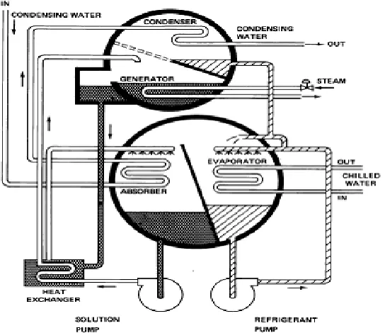
On the other hand, the VARS works on the only low grade energy i.e. Heat. It is always preferred if there is some scope of waste heat from industries or some other sources. It can be combined and used with power plants where there is a huge scope of waste heat. VARS contains a generator that heats up the mixture of weak and strong refrigerant. It eliminates the energy consuming device
of VARS called compressor, which has moving parts and requires maintenance. Ammonia-Water (NH3-H2O)is commonly used as a
Fig 2: Vapour Absorption Refrigeration System.
VARS has a lower COP I and COP II because it works on the low grade energy when compared to Vapour Compression
Refrigeration System. The scopes to improve the performance of the VCRS are being researched upon.
II. LITERATURE REVIEW
absorber and the two generators. S.C. Kaushik et al. (2009) presented the energy and exergy analysis of single effect and series flow double effect water–lithium bromide absorption systems. They developed a computational model for the parametric investigation of the systems. Berhane H. Gebreslassie et al. (2010) performed an exergy analysis, which only considered the unavoidable exergy destruction, conducted for single, double, triple and half effectWater–Lithium bromide absorption cycles. Gulshan Sachdeva et al.(2014) performed anexergy analysis of VAR system using LiBr-H2O as working fluid with the modified Gouy-Stodola approach. Karl Ochsner (2008)et al. (2008) developed a new CO2-heat pipe with high-grade steel corrugated pipe system, which – contrary to other pipe systems permits raw length up to 100 m. They also described the establishment of the heat pump system in general. Guilherme B. Ribeiro et al. (2010) investigated a novel evaporator design for a small-scale refrigeration system whose function is to assist the existing heat pipe technology currently used in chip cooling of portable computers. Chengchu Yan et al. (2015) presented a seasonal cold storage system that uses separate type heat pipes to charge the cold energy from ambient air in winter automatically, without consuming any energy. Dr. R.E. Critoph et al. observed carbon - ammonia refrigerators driven by the heat of steam condensing in a thermo-syphon heat pipe. The heat source can be such as solar energy, biomass, or combinations of the two.
In various researches performed, LHPs are being used directly to maintain temperature of several cold storages around the world. It has high heat flux capacity. After reading available research papers following gaps can be identified: There are types of VAR systems such as Single Effect, Double Effect, and Triple Effect etc. in which First Law and Second Law have been studied. But Heat Pipes can be made an integral part of the system and these valuable analyses can be executed on this new system and results can be studied in a comprehensive manner. Waste heat going to the environment from condenser has never been used, which can be supplied back to the generator, requiring low grade energy for its operation. Also the VAR system can be coupled with other systems may be refrigerating or power generating, in which heat is released. The Loop Heat Pipes will make the system compact, and that effect must be studied to optimize the performance of the VAR systems.
The VAR system uses low grade energy for its operation, which can be obtained from several cheaply available sources (solar, waste heat etc). The COP is low and irreversibility related to heat transfer in the cycle is associated. With the use of a Loop Heat Pipe, external heat sources can be connected which will increase the COP of the system. For optimizing a VAR system a LHP can be used to utilise the waste heat for intra-cycle heat exchange, which will eventually increase the First Law COP, Second Law COP and will reduce the irreversibility connected with the operation of a VAR system.
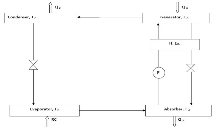
III. SYSTEMS DESCRIPTION
Fig 3 below shows a simple VARS system that works between the temperature range 373K and 278K and its condenser and absorber are at surrounding temperature. It has a generator, absorber, evaporator and a condenser. The system follows the standard VAR cycle.The refrigeration capacity of the system is 90kW. The heat input in generator is107kW. Heat being rejected in the Condenser to the surrounding is 85kW.
[image:4.612.142.497.493.704.2]The Fig 4 exemplifies a modification in the simple VARS with using a LHP. This LHP will perform the Intra-Cycle heat exchange in the system by absorbing the heat from the condensing strong refrigerant exiting the generator and using that heat to be supplied to the mixture exiting the absorber and before entering the generator, reducing the requirement of heat input in generator. Considering different materials in the LHP the amount of the heat re-usable in the system can be varied and thus simulation will show the
changes in the COPI& COP II. Improvements in the performance and there comparison is also plotted with the help of simulation.
The heat leaks in LHP also has some impact on the performance of this system, hence the plots are developed for QLeak and QCond.In
this system several bulky components like Heat Exchangers are removed saving cost and irreversibility connected to it. Heat exchange will also become faster as the heat transfer rate is very good with LHP.
[image:5.612.117.501.211.446.2]The table 1 has the list of the terms used in the research work.
Fig.4: Modified VARS with a LHP [34].
Table 1: Terms Used in Simulation
Terms Abbreviations
Refrigeration Effect in kW RE (kW)
Heat rejected in absorber in kW Qa(kW)
Heat supplied in generator in kW Qg (kW)
Heat rejected in condenser of LHP in kW Qcond(kW)
Heat absorbed in evaporator of LHP in kW Qeva(kW)
Absorber Temperature in K Ta,TA(K)
Generator Temperature in K Tg, TG (K)
Condenser Temperature in K Tc (K)
Evaporator Temperature in K TE,Te(K)
Heat Rejected in Condenser in kW QC (kW)
First Law Coefficient of Performance COP I
Second Law Coefficient of Performance COP II
Heat Leaked from the LHP in kW QLeak (kW)
[image:5.612.82.529.485.740.2]Performance
Percentage Improvement in Second Law Coefficient of Performance
%COP II imp
Improvement in First Law Coefficient of Performance
COP I imp
Improvement in Second Law Coefficient of Performance
COP II imp
IV. RESULTS AND DICSUSSIONS
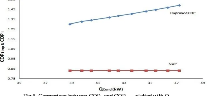
The Fig 5 & Fig 6 show the variations of COP I and Improved COP I in the modified system with the heat utilised through the
condenser of LHP, QCondand the total heat leaked from the LHP, QLeak. The amount of heat utilized in the condenser can be
improved by the materials used in the LHP as they improve the Effective Wick Area, Figure of Merit, Pore radius, Wick Angle and
[image:6.612.133.491.261.427.2]Capacity as a whole. [33]
Fig 5: Comparison between COP I and COP I imp plotted with QCond
Also the leakage of heat from LHP will also be controlled. The above mentioned figures show that as the QLeakincreases,
QCondreduces and hence reduces the improvement of COP I and vice-versa. The relation between the Improvement of COP I and the
QLeak&QCondis more or less linear. By reducing the leakage the COP can be increased. The average COP Iforthe improved system is
[image:6.612.143.484.507.707.2]1.4 where as the simple cycle had a COP I of 0.83.
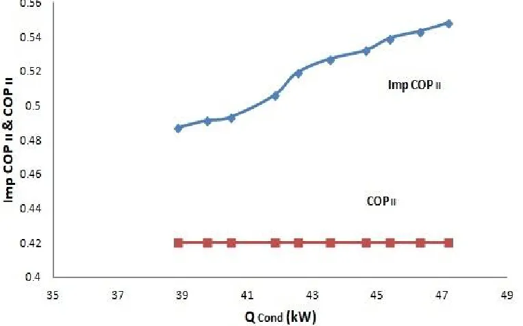
Similarly Fig 7 and Fig 8 show the variations of COP II and Improved COP II in the modified system with QCondandQLeak. As the
QLeakincreases, the exergy losses increase and the Improved COP II decreases along with it. After the improvement, COPII is 0.51,
[image:7.612.124.506.127.365.2]whereasfor simple VARS the COPII is 0.42.
[image:7.612.126.496.400.648.2]Fig 7: Comparison between COP II and COP II imp plotted with Q Cond
Fig 8: Comparison between COP II and COP II imp plotted with QLeak
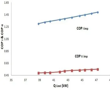
In Fig 9 & Fig 10, the COP I and COP II of the modified system are analysed with varying QCondandQLeak. The COP I has larger
fluctuations with the QCondandQLeak. on the other hand this comparative plot shows that the COP II variations are more are less
Fig 9: COP I imp and COP II imp plotted with QCond
Fig 11: Variation of %COP I imp and % COP II imp plotted with Qcond
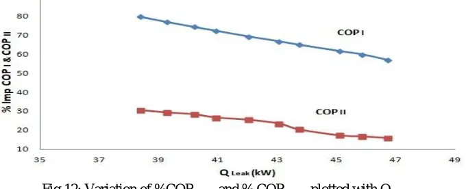
The fig 11 & fig 12 deals with the % improvement in the COPI and COP II while using the heat from the LHP. The average
improvement in COP I is 68% and that for the COP II is 23%. Gradual and steady increase can be seen in the performance as the heat
utilization increases.
Fig 12: Variation of %COP I imp and % COP II imp plotted with QLeak
V. CONCLUSIONS
After the study of the results and inferring from them, the following conclusions can be made:
A. The utilization of heat increases with the change in design and materials of the LHP.
B. By reducing the QLeakthe COPI increases. The average COP I forthe improved system is 1.4 where as the simple cycle had a
COP I of 0.83.
C. After the improvement, COP II is 0.51, whereas for simple VARS the COPII is 0.42.
D. COP I& COP II increase by good margin of 68% and 23% respectively.
E. The size of the system is reduced and the parts having anergy are reduced.
F. Further improvements can be achieved if more heat pipes are incorporated at various.
REFERENCES
[1] Saeed. Sedigh , Hamid. Saffari ,”Thermodynamic analysis of single effect and half effect absorption refrigeration system” International Journal of Energy &
Technology Vol.25 (2011) 1-9.
[2] S. Arivazhagan , R. Saravanan , S. Renganarayanan ,” Experimental studies on HFC based two-stage half effect vapour absorption cooling system” Applied
[image:9.612.142.482.347.485.2][3] GulshanSachdeva, Ram Bilash,” Thermodynamic Analysis of a Vapor Absorption System Using Modified Gouy-Stodola Equation” International Journal of Computer, Electrical, Automation, Control and Information Engineering Vol:8, No:12, 2014.
[4] I. Horuz,” A comparison between Ammonia-water and Water-Lithium Bromide solutions in Vapor Absorption Refrigeration Systems” Int. Comm. Heat Mass
Transfer, Vol. 25, No. 5, pp. 711-721, 1998.
[5] Abdul Khaliq, and Rajesh Kumar,” Exergy analysis of double effect vapor absorption refrigeration system” Int. J. Energy Res. 2008; Vol.32:161–174.
[6] S.C. Kaushika, AkhileshArora,” Energy and exergy analysis of single effect and series flow double effect water–lithium bromide absorption refrigeration
systems” international journal of refrigeration Vol.32 ( 2009 ) 1247 – 1258.
[7] RabahGomri , RiadHakimi,” Second law analysis of double effect vapour absorption cooler system” Energy Conversion and Management Vol.49 (2008) 3343–
3348.
[8] S.A. Adewusi, Syed M. Zubair,” Second law based thermodynamic analysis of ammonia–water absorption systems” Energy Conversion and Management Vol.
45 (2004) 2355–2369.
[9] RabahGomri,” Second law comparison of single effect and double effect vapour absorption refrigeration systems” Energy Conversion and Management Vol. 50
(2009) 1279–1287.
[10] R.D. Misra, P.K. Sahoo, S. Sahoo, A. Gupta,”Thermoeconomic optimization of a single effect water/LiBr vapour absorption refrigeration system” International Journal of Refrigeration Vol.26 (2003) 158–169.
[10] M. Belghazi, A. Bontemps, C. Marvillet,” Experimental study and modelling of heat transfer during condensation of pure fluid and binary mixture on a bundle
of horizontal finned tubes” International Journal of Refrigeration Vol.26 (2003) 214–223.
[11] M.M. Talbi, B. Agnew,” Exergy analysis: an absorption refrigerator using lithium bromide and water as the working Fuids” Applied Thermal Engineering Vol.
20 (2000) 619-630.
[12] E. Kurem,” A comparison between Ammonia-water and Water-Lithium Bromide solutions in vapour absorption heat transformers “In. Comm. Heat Mass
Transfer; Vol. 28, No. 3, pp. 421-438, 2001.
[13] Da-Wen Sun,” Comparison of the performances and NH3-H20, NH3-LiNO3 and NH3-NaSCN Vapor Absorption Refrigeration Systems” Energy Convers.
MgmtVol. 39, No. 5/6, pp. 357-368, 1998.
[14] Yu.F. Maydanik,” Review Loop heat pipes” Applied Thermal Engineering Vol.25 (2005) 635–657.
[15] Randeep Singh, AliakbarAkbarzadeh , MasatakaMochizuk,” Operational characteristics of a miniature loop heat pipe with flat evaporator” International Journal
of Thermal Sciences Vol.47 (2008) 1504–1515.
[16] T.X. Li, R.Z. Wang , L.W. Wang, Z.S. Lu, C.J. Chen,” Performance study of a high efficient multifunction heat pipe type adsorption ice making system with
novel mass and heat recovery processes” International Journal of Thermal Sciences Vol.46 (2007) 1267–1274
[17] Yuan-Ching Chiang , Wen-Cheng Kuo , Chia-CheHo , Jen-JieChieh,” Experimental study on thermal performances of heat pipes for air-conditioning systems
influenced by magnetic nanofluids, external fields, and micro wicks” International Journal of Refrigeration Vol.43 ( 2014 ) 62 -70.
[18] T.X. Li, R.Z. Wang, L.W. Wang, Z.S. Lu,” Experimental investigation of an innovative dual-mode chemisorption refrigeration system based on multifunction
heat pipes” International Journal of Refrigeration 3 1 ( 2 0 0 8 ) 1 1 0 4 – 1 1 1 2.
[19] L. GarousiFarshi a,*, C.A. Infante Ferreira b, S.M.S. Mahmoudi a, M.A. Rosen,” First and second law analysis of ammonia/salt absorption refrigeration
systems” International Journal of Refrigeration Vol. 4 0 ( 2 0 1 4 ) 1 1 1-1 2 1.
[20] T.X. Li, R.Z. Wang , L.W. Wang, Z.S. Lu, J.Y. Wu,” Influence of mass recovery on the performance of a heat pipe type ammonia sorption refrigeration system
using CaCl2/activated carbon as compound adsorbent” Applied Thermal Engineering Vol. 28 (2008) 1638–1646.
[21] Z.S. Lu , L.W. Wang, R.Z. Wang,” Experimental analysis of an adsorption refrigerator with mass and heat-pipe heat recovery process” Energy Conversion and
Management Vol. 53 (2012) 291–297.
[22] Behrooz M. Ziapour*, Mohsen Tavakoli,” Performance study on a diffusion absorption refrigeration heat pipe cycle” International Journal of Thermal Sciences
Vol.50 (2011) 592-598.
[23] Basant K. Agrawal*, Munawar N. Karimi,” Thermodynamic performance assessment of a novel waste heat based triple effect refrigeration cycle” International
Journal of Refrigeration Vol. 3 5 ( 2 0 1 2 ) 1 6 4 7-1 6 5 6.
[24] Behrooz M. Ziapour*, Mohsen Tavakoli,” Performance study on a diffusion absorption refrigeration heat pipe cycle” International Journal of Thermal Sciences
50 (2011) 592-598.
[25] T.S. Jadhav , M.M. Lele,” Theoretical energy saving analysis of air conditioning system using heat pipe heat exchanger for Indian climatic zones” Engineering
Science and Technology, an International Journal Vol. 18 (2015) 669-673.
[26] Chengchu Yan , Wenxing Shi , Xianting Li , Shengwei Wang,” A seasonal cold storage system based on separate type heat pipe for sustainable building
cooling” Renewable Energy Vol.85 (2016) 880-889.
[27] Matthias H. Buschmann,” Nanofluids in thermosyphons and heat pipes: Overview of recent experiments and modelling approaches” International Journal of
Thermal Sciences Vol.72 (2013) 1-17.
[28] P.D. Dunn, D.A. Reay, Heat Pipes, Pergamon Press, Oxford, 1993.
[29] D.Reay, Heat Pipes-Theory, Design and Applications, Butterworth-Heinemann,Oxford, Fifth edition 2006.
[30] Korn, F., “Heat Pipes and its Applications” Project Report 2008 MVK160 Heat and Mass Transport May 07, 2008, Lund, Sweden.
[31] Rajashree, R., Rao, K.S., “A Numerical Study of the Performance of Heat Pipe” Indian Journal of Pure and Applied Mathematics, 21 (1): 95-108, January 1990.
[32] C.P. Arora, Refrigeration and Air Conditioning, Tata Mcgraw-Hill Publishing Company Limited,Delhi, Third Edition, 2009.
[33] AnkitDwivedi, R. S. Mishra,” Thermodynamic Analysis of Heat Pipe Using Ammonia, Water and Ethanol with a View to Being Used in Refrigeration” ISSN
2347 - 3258 International Journal of Advance Research and Innovation, Volume 3, Issue 3 (2015) 498-502.
[34] AnkitDwivedi, R. S. Mishra, Manjunath K,”Optimization of Vapour Absorption System Using Heat Pipes” ISSN: 2321-9653 International Journal for Research
![Fig 1: Circular process of a Loop heat pipe [30]](https://thumb-us.123doks.com/thumbv2/123dok_us/8295757.852791/2.612.189.444.446.639/fig-circular-process-loop-heat-pipe.webp)
![Fig.4: Modified VARS with a LHP [34].](https://thumb-us.123doks.com/thumbv2/123dok_us/8295757.852791/5.612.82.529.485.740/fig-modified-vars-with-a-lhp.webp)