6
I
January 2018
Android Based Human Robot Interaction System
for Localisation
Jackulin S 1, Jerwin Prabu A2, Jenifer S 3
1
Research Student, Department of Electronics and Telecommunication, Karpagam College of Engg, Coimbatore 2
Head of Technology, Department of Research and Development, BRS India Pvt Ltd, Pune 3
Research Student, Department of Electronics and Communication, Francis Xavier College of Engg, Tirunelveli
Abstract: This project developed to utilize Android Mobile as a robot controller since its all the more powerful and equipped with several powerful sensors that are exceptionally helpful for robots safe navigation system and path finding framework. The research uses Android framework as well as Arduino microcontroller to locate and control the robot by means of in-band telecommunication signalling system from different separation. Gyroscope, magnetometer and accelerometer sensor is utilized as contribution to trigger mobile robot development for localization purpose. This way, robots may collaborate in an indistinguishable area from clients control them from any place in the world utilizing internet and wireless networks for this purpose. The input sensor is intended to create in-band media transmission system framework based on North Pole direction and power the robot to move just a single bearing referenced by North Pole, lot of investigation have been done, for example network provider analysis, robot administrator analysis, sensor analysis as well as robot localization analysis. The versatile robot could be controlled by means of created developed Android application and all analyses with respect to robot performance execution are taken for future advancement reason. Alongside straightforwardness comes the advantage of having the capacity to reduce costs to a minimum, undertaking that has been planned and constructed. At last, on one side, an economical and almost completely printable robot has been designed and built, and on the other side both the robot’s product software and the Android phone’s software have been developed, bringing about an android controlled robot.
Keywords: Wireless Sensor Networks, Multipath Routing, Energy Consumption, Data delivery ratio, Load Balancing, throughput and link quality.
I.INTRODUCTION
A.Machine Interaction System
Cell phone has turned out to be a standout amongst the most famous electronic gadgets as of late. Because of its notoriety, many architects, academicians, or scientists intrigued to use every one of the upsides of cell phones in their investigates. Moreover, current machine connections have an assortment of advanced inherent sensors that can be investigated to construct robot; in particular as controller for the robot. Controller is the primary part particularly for portable robots. It is act like a "mind" for the robot. There are a few ways to deal with create controller interface and it is relies upon the cost or prerequisites. Essentially, the regular way to deal with outline a robot is by utilizing microcontroller. This approach suit for instructive reason since it is ease and simple to develop. Sensors and actuators (SAs) will be associated specifically to the microcontroller, for example, the Microchip PIC or Atmel (Arduino) and the program's designs at that point composed by utilizing programming dialect and after that it is slowed down in the microcontroller's ROM. Be that as it may, microcontroller for the most part has impediment in term of preparing which is determine has under 100MHz handling unit and its memory is often of a few Kilobytes or less. To influence this way to deal with turn out to be all the more effective in handling framework, a PC will be utilized as the controller. Now, microcontroller is utilized to peruse sensors as information sources and control actuators at the yields while the fundamental control (program's engineering) keep running in the PC through particular working framework relies upon the sorts of microcontroller.
B.Localization strategies and Interface
between sensors, actuators and the primary PC. Every one of these kinds of controller interface rely upon computerized hardware part. So as to apply the robot's controller, most robot architects utilize microcontrollers or PCs and different understanding sensors that acquired to manufacture the robot's detecting frameworks. Purchasing every one of the sensors generally installed in a cell phone would unquestionably more costly than purchasing another cell phone. Moreover, the majority of the cell phones these days fueled with processors quicker than 1GHz, routinely multi-center and 1 GB of Smash memory or more. Also, many tasks as of now were made meaning to utilize cell phones as the robot's principle controller as a result of its ability to execute complex apply autonomy calculations in spite of the fact that with a 300MHz form in processors, in addition to the greater part of the present cell phones have an assortment of implicit sensors that can be found. Huge numbers of them have accelerometer, camera, Wi-Fi, Bluetooth, speakers, amplifier, Worldwide Situating Framework (GPS) collector, compass, and some even have stereo camera for 3D imaging and in addition spinners. This different sensors inside a cell phone has lead creators to give a basic robot's equipment design yet with an extraordinary computational stage. In addition, with a basic engineering, it additionally valuable for instructive mechanical autonomy since understudies can manufacture their own robots with ease and uses them as stage for tests like building up the localisation systems for a portable robot.
C.Problem Statement
For as far back as couple of years, regular usage more often than not includes costly sensors and equipment with intense registering capacity to build up a robot. For instance, a robot that controlled by a joystick influence higher cost because of the outside sensors utilized or some other interfacing circuit between the joystick and the robot like a gadget named NXT programming pack. As of late, to plan a robot alongside route registering stage isn't an issue any longer. In apply autonomy, route alludes to the way a robot discovers its way in the earth and is a typical necessity for any versatile robots. Today cell phone officially outfitted with numerous inherent sensors for route purposed like accelerometer, gyrator, camera, GPS, and Wi-Fi handset in addition to the greater part of them implanted with quick processors. The fashioners have wide alternatives to pick any inherent sensors to make their route stage of their robots. It resembles utilizing the cell phone as "mind" for the robots. In this task, by utilizing the Dual Tone Multi Frequency (DTMF) association, the robots could be controlled in the wide range zone more than different associations, for example, Infrared, Wi-Fi, WLAN or Bluetooth since DTMF innovation is one of the remote correspondence hone used to control the robots. Ordinary practice for recent years back, robots are controlled by utilizing RF circuits, which have a few impediments like working reach, recurrence range and control run. These restrictions could be vanished by utilizing cell phones for mechanical control; in addition to they have more focal points like powerful control, vast working extent scope and the greatest preferred standpoint is durable controlled. For correlation, from [1] definition; "Wi-Fi is a modest arrangement expected to cover short separations, for example, airplane terminal, inns, and meeting territories". From this, obviously Wi-Fi as a few confinements in giving wide scope arrangement, while the Infrared, WLAN, and Bluetooth innovation just ready to remote some hardware in the scope not as much as Wi-Fi.
II.RELATED WORK
This session discussed the analysis about earlier existing projects and has been divided into two segments. From types of controller interface, the discussion also covered into several localisation strategies that has been developed in recent years.
A mobile robot (G.N. Coelho, 2008) [2] with Bluetooth connection as the interface medium has noticed several navigation problems which are including mapping, localization and path planning. This project evaluates performance of the navigation algorithms, by comparing executions time and memory usage between Nokia N80, Nokia N95, and a computer desktop.
Then a wired and wireless robot called with ARM Cortex processor (Jerwin Prabu A, 2014) [3] with WLAN connection as the interface medium and the beagle bone black model is chosen as its “brain”.
The GUI application named Robot Tele-operation Maemo User Interface (RTMU) essentially an ARIA (Advanced Robot Interface for Applications) client is an open-source software development kit based on C++ programming language. This GUI application will be programmed into the N770 and the robot movement is controlled via WLAN connection. According to project analysis, a main problem has been indicated in which it is hard to maintain the WLAN signal strength [4].
For outdoor positioning, by using GPS is not a big problem since GPS technology is the best solution for positioning and navigation tasks [6]. All the positions data is determined from the sensors that attached to the robot frame and not depends on the built-in sensors from the mobile phone.
Another mobile robot controlled by DTMF technology is developed for stair climbing (T. S. Vamsi, K. Radha, 2013) [7]. The received tone is decoded into 4 bit binary number by using MT8870 DTMF decoder and processed through the LPC2148 controller. The controller then give the instruction based on the pre-programmed codes to the motor and robot will moves for a specified direction.
III. IMPLEMENTATION OF PROPOSED MODEL
For simple understanding about the localization term, it can be summarized with three questions; “where am I?”, “where am I going?” and “how should I get there?” Localization is the process of assessing the location of robot, relatively to some model of the environment by using any sensor measurements that available. As the robot keeps moving, the estimation of its position drifts and changes, and has to be kept updated through active computation.
A.Localization by concurrent observation
The objective of this framework is to utilize the counterfeit reference point frameworks and contrast and the structure of regular indoor situations without changing the earth. This framework is utilizing the broadened Kalman channel (EKF) to take care of versatile robot route issue in a known situation.
Fig.1. Localization by concurrent observation of several geometric beacons
From a man-made indoor condition, each component from nature is displayed to be a geometric target. This geometric reference point is an exceptional sort of focus on that can be dependably seen in progressive sensor estimations (ultrasonic sensor) and that can be precisely portrayed as far as a succinct geometric parameterization. In view of Figure 2 , the limitation calculation will be created from this plant demonstrate.
Fig.2. Localization by concurrent observation of several geometric beacons
At that point a dream based confinement for robot is created in an organized situation. The restriction framework depends on a coded design put on the base of the surface. This framework will gauge the position, introduction and also speed of the submerged robot through segments like on-board down-looking camera and a coded design as said above. The calculation figures the 3D position and introduction to the surface organize framework, with calculation of the vehicle's speeds, including surge, influence, hurl, move, pitch and yaw by utilizing the speed based low level controller of the robot. The restriction calculation which intended to work at 12.5Hz contains a few stages; a) design location, b) dabs neighbourhood, c) dabs worldwide position, and d) position and introduction estimation. From the outcome, the confinement framework has float free estimations because of the state of surface, in addition to there is no immediate light from the Sun that will impact the earth's brightening. Next, visual historic point acknowledgment by utilizing strong shading counterfeit milestones is proposed for a portable robot as one of the confinement system. This technique connected by utilizing round and hollow moulded items with strong shading as simulated points of interest, on the grounds that a basic obvious historic point in rectangular shape can be given from any side perspective where the portable robot perception could happen. With a similar strategy proposed by [17]; the framework recognizes one point of interest, arranges the milestone and computes its separation and introduction to the visual sensor (worked in camera) and just a single historic point will be distinguished for a picture caught.
B.Maintenance of Distance And Orientation
The idea of ideal separation way is utilized to evaluate the base vitality utilization. The fundamental point is to keep up the information parcel stream in the remote sensor arrange unhampered. The meaning of the sensor arrange demonstrate is given as takes after. The preparing will experience in division and picture clamour lessening. Give us a chance to accept a given hub N ( ) is made out of hand, where is the arrangement of hubs and is the arrangement of connections. Because of the component of multi-jump transmission, sensor system could have numerous ways from source hub s to goal hub d. Accordingly, let Π (s,d) mean the arrangement of every single conceivable way beginning from s to d. As indicated by these definitions, it is realized that Π (s,d) is the subset of Λ. Let π speaks to a bland way, and πi(s, d) speaks to I-th way in an adventure from source hub s to goal hub d. Give Φ(π) a chance to be a bland cost work related to an assigned way π. Φ(π) can be the postpone time θ(π) for a bundle which exchanges through a way π, or the quantity of bounces ε(π), even a crossover work consolidated them two. From this procedure, if more perplexing conditions utilized, the shading picture division counts will turn out to be all the more difficult and need a cell phone with higher preparing unit to execute the limitation calculations. On the off chance that the Connection lattice is meant as Ts = (ts,d) where Ts is a cluster that registers every single active connection of hub s, and ts,d decides if hub s has an active connection associated with hub d or not, 1 speaks to associated, 0 speaks to disengaged.
Figure 3: (a) Model of robot motion; (b) Model of location measurement
Let Bs,d denotes the bandwidth utility ratio of link from node s to node d. ps,df determines the probability table for deciding the next node of a packet transferring from node s to its final destination node df. ps,df,j corresponds to the probability for the packet transferred to node j. Note that Σj (ps,df,j) = 1. Also, suppose Efull is the initial energy on each node and Ej is the remaining energy on node j. The weight of choosing node j as the next node for transferring the packet while the packet is queued at node s is,
W(s,j,df)=ts,j(ps,df,j)C1(1-Bs,j)C2(Ej/Efull)C3 (1)
Where C1, C2 and C3 are weighting factors that regulate the importance of probability matrix (ps,df), bandwidth utility ratio (Bs,j), and remaining energy ratio (Ej/Efull) during routing process, respectively.
The values of C1, C2 and C3 are set as 1 in most cases. Supervisors can obtain desired performance by adjusting these parameters. There is no systematic approach to obtain the optimal values of these parameters since it involves too many human factors. Hence, generally, we set the values of C1, C2, and C3 to 1. The probability of choosing node j as next node of the packet can be defined as
follows
The possibility of selecting a path πi(s, d) to transfer a packet from node s to node j is updated by the following equation,
)
[ (, ) ( , )]))
,
(
(
(
,
,
f if sj isds
j
s
i
Q
j
d
p
(2)C. Determination of Path Stability
Let Nb denote the neighbour set of node b and node b will choose the next hop by following the criterion
)] ) 1 ( 1 ( [ , ,)
1
(
min
arg
oe b d dh init j remaining j N l cte
e
L
(3)Where doe is the distance in hops between node o and sink e; dkeis the distance in hops between node k and sink e; Δdh is the
difference between doeand dkeej,initis the initial energy level of node j,ej,re
maining is the remaining energy level of node j; and
is the weight factor and
> 1. Note that (Δdh+1) ∈ {0, 1, 2} and (1−ej,remaining /ej,init) ∈(0, 1). The link cost function takes both the node energy level and hop distance into account. Suppose ej,remainingremainsconstant. In this case, the link cost increases when (Δdh+1) increases. On the other hand, suppose (Δdh +1) remains constant. In this
case, the link cost increases as ej,remainingdecreases. The weight factor
adjusts the priority. A large
gives more weight to thenode energy than to the hop distance. All these methods have several specific purposes in which to determine the robot’s shortest path, the Tangent method is used, to estimate the robot’s location; the Kalman filtering algorithm is applied while to modify navigating error, FLC will be used. The approach is based on the developed model for mobile robot motion and location measurement.
D.Complex Analysis Model
[image:8.612.151.463.474.645.2]From this, a mind boggling investigation needs to perform inside high preparing microchip keeping in mind the end goal to settle the Tangent and Kalman separating calculation. The vitality utilization of sitting is constantly spent by the hubs to maintain a strategic distance from crashes, which is the capacity of base layer. The aggregate vitality utilization can be considered as the vitality utilization of sending and getting a bundle duplicated by the aggregate transmission times. Two cell phone show has been utilized which are the LG Optimus P970 (a low-end double center processor) and the HTC One X+ (a top of the line quad-center processor) for correlation purposed. From the begin, the procedure separated into three fundamental procedures; a) versatile robot plan and development; b) the Android program advancement; and c) the mix amongst cell phone and portable robot through DTMF decoder module where the restriction techniques will occurred in this part.
Figure 3.2: Robot motion Block Diagram
Regularly a versatile robot comprises of at least one driven haggles discretionary detached or caster haggle controlled wheels while most plans require two engines for driving and directing a portable robot. The parts and equipment can be outlined by a piece graph that is appeared in Figure 3 .2. Real segments are two DC equipped engines (SPG30E-30K) with encoder, the 10A NMOS H-Bridge engine driver, the Arduino Uno microcontroller, the DTMF module (MT8870), and a cell phone. The DC adapted engines were picked as the determined instrument in this task due to it is anything but difficult to control, spotless, calm and the most well known utilized as a part of portable robot plan. The qualities are appeared in Figure 3 .4. From the figure, the greatest torque (slow down torque) equivalent to 23.5m Nm at 1.8A (slow down current), while for proficiency (half of obligation rate), the appraised torque equivalent to 5.88m Nm at 0.41A (evaluated current).
Figre 3.3: SPG30E-30K DC Motor characteristics
Table 3 .3.1: (a) Clockwise Rotation
[image:9.612.191.401.557.683.2]For further understanding, Table 3 .1 (a) and (b) is showing the state diagram that will be produced by the encoder; consequence from the rotational movement of the DC motor. For interfacing, the fully NMOS H-bridge dual channel 10A motor driver is needed to drive both DC motors for forward and backward movements. It is designed to drive two DC motor with high current up to 10A continuously without the heat sink since it has been integrated with fully NMOS H-bridge.
Table 3 .3.2: (b) Counter Clockwise Rotation
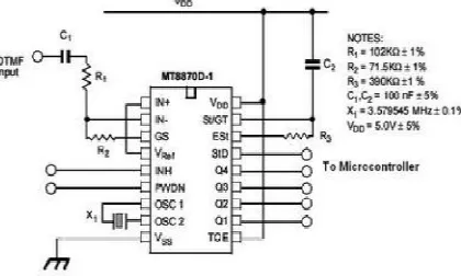
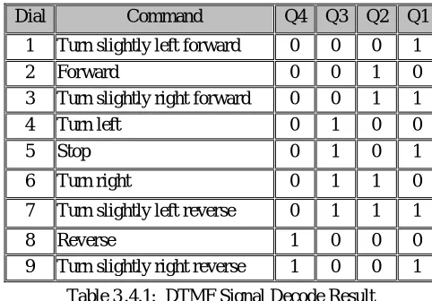
Smartphone will be attached on the robot chassis to utilize the built-in sensors and connected to the DTMF decoder module, MT8870. The Arduino microcontroller will be ruled to translate 4-bit data from DTMF module to control the PWM for DC motor via H-bridge motor driver. PWM is a technique for getting analogue results with digital means. Digital control will be used to form a square wave (a signal switched between on and off). This on-off pattern can simulate voltages in between full on (5V) and off (0V) by changing the portion of the time the signal spends on versus the time that the signal spends off. The pulse width term came from the duration of “on time signal” in the square wave. A code “analogWrite ( )” is on a scale of 0-255 bits since Arduino Uno has 8-bits binary output. For example, to get the maximum speed for DC motor, the code will be written as “analogWrite (255)”. DTMF decoder module, type MT8870 is used for decoding the mobile DTMF tone signal received from the smartphone into 4-bit digital. The decoder is operated with a 3.58 MHz crystal along with capacitor (C1) used to filter the noise and two unit resistors (R1 and R2) is used to amplify the input signal. In this project, the module is connected to smartphone through audio jack. DTMF signals in 4-bit data that will be used according to buttons 0 to 9 including button # (hash) and * (star). Each dial signal is decoded into 4-bit data and will be sent to Arduino microcontroller to control DC motors (movements of mobile robot).
Figure 3 .4: The schematic diagram for MT8870
PHASE Signal A Signal B
1 0 0
2 0 1
3 1 1
4 1 0
PHASE Signal A Signal B
1 1 0
2 1 1
3 0 1
Table 3 .4.1: DTMF Signal Decode Result
The last real segment to outline and build versatile robot in this venture is cell phone. This model is picked in view of its handling execution which it was coordinated with Quad-Core processor with 1.6 GHz CPU speed. This intense processor can give more productivity to complex calculation computation particularly to make localisation systems.
IV.CONCLUSION
This task created to utilize Android Mobile as a robot controller since it's all the more effective and furnished with a few capable sensors that are exceptionally helpful for robots safe route framework. All route robot requests the some kind of deterrent discovery, thus obstruction shirking technique is of absolute significance. Hindrance evasion robot has a huge field of use. They can be utilized as administrations robots, with the end goal of family unit work thus numerous other indoor applications. In those testing situations, the robots need to assemble data about their surroundings to stay away from hindrances. These days, even in conventional conditions, individuals additionally require that robots can identify and maintain a strategic distance from hindrances. For instance, a mechanical robot in a production line is required to maintain a strategic distance from specialists so it won't hurt them. All in all, snag evasion is broadly investigated and connected on the planet, and it is plausible that most robots later on ought to have impediment shirking capacity. Different procedures have risen to build up the investigation of apply autonomy and robots. Those which perform best are utilized as a model to make a consequent "age" of robots. There are worries about the expanding utilization of robots and their part in the public eye. Extra highlights can be effectively joined into this module if required, long range sensors can be utilized. The speed of the robot can be controlled. A wire-less RF remote can be utilized to control the robot, utilization of differential controlling with progressive change in wheel speeds. Addition in number of sensors to improve the snag recognition capacity, the last significant segment to plan and build versatile robot in this undertaking is cell phone. This model is picked in view of its handling execution which it was coordinated with Quad-Core processor with 1.6 GHz CPU speed. This effective processor can give more proficiency to complex calculation computation particularly to make localisation systems. The portable robot could be controlled by means of created Android application and all investigations in regards to robot execution is taken for future advancement reason.
REFERENCES
[1] S. Tang, “Performance analysis of an integrated wireless network using WiMAX as backhaul support for WiFi traffic,” 2011 - MILCOM 2011 Mil. Commun. Conf., pp. 1833–1837, Nov. 2011.
[2] G. N. Coelho, “Autonomous Mobile Robot Navigation using Smartphones Extended Abstract,” 2008.
[3] Jerwin Prabu A, J. Narmada, Jaya Prakash, “Artificial Intelligence Robotically Assisted Brain Tumour Surgery”, International Organisation of Scientific Research (Journal of Engineering), Vol.4, Issue.5, 2014, pp.110-130.
[4] “Ehab Aboudaya, Lappeenranta Univ. Of Technol. Finland, ‘Mobile Teleoperation of a Mobile Robot’, Thesis for the Degree of Master of Science in Technology, 2010.”
[5] K. M. Al-Aubidy, M. M. Ali, A. M. Derbas, and A. W. Al-Mutairi, “GPRS based remote sensing and teleoperation of a mobile robot,” 10th Int. Multi Conferences Syst. Signals Devices 2013, pp. 1–7, Mar. 2013.
[6] V. Nakka and A. Kabirdas, “Design and Realization of Augmented Reality Based Navigation Assistance System,” vol. 2, no. 6, pp. 2842–2846, 2011. [7] T. S. Vamsi and K. Radha, “ARM Based Stair Climbing Robot Controlling Through DTMF Technology,” no. 3, pp. 71–74, 2013.
[8] P. Ridao, R. Garcia, and T. Nicosevici, “Vision-based localization of an underwater robot in a structured environment,” 2003 IEEE Int. Conf. Robot. Autom. (Cat. No.03CH37422), vol. 1, pp. 971–976, 2003.
[9] M. Thesis and C. Science, “ANALYSIS OF THE B LUETOOTH,” no. June, 2009.
Dial Command Q4 Q3 Q2 Q1
1 Turn slightly left forward 0 0 0 1
2 Forward 0 0 1 0
3 Turn slightly right forward 0 0 1 1
4 Turn left 0 1 0 0
5 Stop 0 1 0 1
6 Turn right 0 1 1 0
7 Turn slightly left reverse 0 1 1 1
8 Reverse 1 0 0 0
[10] W.-W. Kao and B. Q. Huy, “Indoor navigation with smartphone-based visual SLAM and Bluetooth-connected wheel-robot,” 2013 CACS Int. Autom. Control Conf., vol. 1, pp. 395–400, Dec. 2013.
[11]J. Bruce, T. Balch, and M. Veloso, “Fast and inexpensive colour image segmentation for interactive robots,” Proceedings. 2000 IEEE/RSJ Int. Conf. Intell. Robot. Syst. (IROS 2000) (Cat. No.00CH37113), vol. 3, pp. 2061–2066, 2000.
[12]K. Yoon and I. Kweon, “Artificial landmark tracking based on the colour histogram,” Proc. 2001 IEEE/RSJ Int. Conf. Intell. Robot. Syst. Expand. Soc. Role Robot. Next Millenn. (Cat. No.01CH37180), vol. 4, pp. 1918–1923, 2001.
[13]G. Huang and H. Lin, “Applications of Highly Accurate Localization and Navigation to Mobile Robot,” no. October, pp. 4758–4763, 2009.
[14]T. Bräunl, Embedded Robotics: Mobile Robot Design and Applications with Embedded Systems, 2nd Editio. Germany: Springer Berlin Heidelberg, 2006. [15]“J. J. Leonard and H. F. Durrant-Whyte. Mobile robot localization by tracking geometric beacons. IEEE Transactions on Robotics and Automation, 7(3):376–