5
IV
April 2017
Design and Development of Main Helicopter Rotor
Blade
K. Balaji1, P. Gracekumar2, K. Mahimaiprabhu3, M. Manikandan4, R. Raghul5 1,2,3,4,5
Aeronautical Engineering, Karpagam Institute of Technology
Abstract: To determine the load distribution in main helicopter rotor blade in study Computational Fluid Dynamics (CFD) and Finite Element Method (FEM) software is used. The aim of the present investigation is the development of a CFD and FEM by using CFD computation procedure capable of accurately simulating the pressure distribution test and velocity test of main helicopter blade and using FEM to simulating flow of thermal behavior test. For this purpose the complete of main rotor blade in CATIA model are used in CATIA modeling. Primary attention in this investigation is focused on defining load on main helicopter rotor blade because of metal trailing edge segments of these blade were replaced with a new segments made from honeycomb composite materials. As critical structural parts with greetings to strength here are glued joints between metal and composite segments of trailing edge are considered. For precise stress analysis of these segments, including glued joints, the finite element method is used.
Keyword- Ansys Fluent, Catia, Cfd, Fem, Rotorblade
I. INTRODUCTION
[image:2.612.42.572.484.697.2]Nowadays, aerodynamic interaction between the main rotor of helicopter still remains a challenging task. The flow around a helicopter is dominated by complex aerodynamics and flow interaction phenomena. Lifting-line theory with two dimensional (2D) airfoil records as a function of angle of attack and Mach number were usually used for blade aerodynamic loads. But in such approach, experiential corrections had to be integrated because of the effects of dynamic stall, compressibility and blade interaction with trailing vortex. Today, powerful computational fluid dynamics (CFD) methods are progressively more used in the analysis of the whole helicopter avoidingexperiential corrections. The additional complexity appears to result from blade dynamics and elastic deformations. The problem of main rotor analyzed in relatively ANSYS FLUENT (ANSYS FLUENT 18.0 Users Guide) commercial software is applied in obtaining influence of the fuselage on the main rotor blade sectional loads for the Mh-50 helicopter. The main rotor blades are modeled whereas rotor hub is not included.
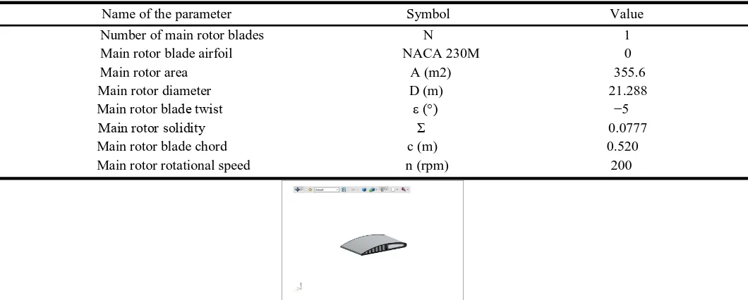
Table 1. Parameters of Helicopter Main Rotork,
Name of the parameter Symbol Value Number of main rotor blades N 1 Main rotor blade airfoil NACA 230M 0
Main rotor area A (m2) 355.6 Main rotor diameter D (m) 21.288 Main rotor blade twist ε (°) −5
Main rotor solidity Σ 0.0777 Main rotor blade chord c (m) 0.520 Main rotor rotational speed n (rpm) 200
Thedata points of airfoil for the rotor model and the computational domain were collected. The 3D model of the main rotor blades are designed by using CATIA. Figure 2 show model of our rotor blade which can design in CATIA are decided to place on the 3D model of the main rotor blade. Figure 3 shows the 3D model of the main rotor blade along with the structure of honey comb inside of main rotor blade. The values for the generated mesh near the wall zones are maintained at too which is as per the turbulence modeling requirements. A single passage approach is modeled and numerically solved with the assumption that flow is periodic within the passage.
Fig.2. Model of Main Rotor Blade
Fig 3 CATIA Modeling
III. MESH GENERATION
Meshing of the computational domain is made using CFD as shown in Figure 3.Thus, the discretisation of the Hybrid structured grid elements were generated. To mesh the composite material carbon epoxy and boron epoxy for analyzing the material in ansys software.
Fig . 5. Meshing of Carbon Epoxy Fig.6. Meshing of Boron Epoxy
IV. RESULT
A. Pressure
In figure7 compeer the pressure flow over the carbon epoxy composite material & boron epoxy composite material by using ansys software for increasing the pressure while changing composite material in helicopter main rotor blade for producing more lift in rotor blade. In below figure we find out the various pressure flows in both composite materials by using ansys software
Fig.7. Comparison of Composite Material
B. Velocity
In figure8 compeer the velocity flow over the carbon epoxy composite material & boron epoxy composite material by using ansys software for decreasing the velocity while changing composite material in helicopter main rotor blade for producing more lift in rotor blade. In below figure we find out the various velocity flows in both composite materials by using ansys software.
The below figure 9 represents the safety factor of the carbon and boron composite respectively.
Fig.9. Comparison of above giving composite material
V. CONCLUSION
Finally by using the software life CATIA, CFD (Computational Fluid Dynamics) and FEM. We are using two different types of composite honeycomb structure they are carbon epoxy honeycomb structure and boron honeycomb structure. By using the software’s we can designing the main rotor blade and we can also found pressure distribution, velocity distribution. The purpose of this paper was to study the flow and performance parameters for better understanding over the design condition.
VI. ACKNOWLEDGMENT
With great pleasure and deep gratitude, authors wish and express their sincere gratitude to beloved Principal Dr. T. Ramachandran
for providing an opportunity and necessary facilities in carrying out this work and express sincere thanks to all the staff members of Aeronautical Engineering whose assistance played a big role in this work and have been of immense value.
REFERENCES
[1] Dieterich O, Enenkl B, and Roth D. Trailing edge flaps for active rotor control: Aeroelastic characteristics of the ADASYS rotor system. Proc AHS 62nd Annual Forum, Phoenix, AZ, 9 - 11 May 2006.
[2] Harika S Kahveci1 & Cengiz Camci2 Turbomachinery Aero-Heat Transfer Laboratory The Pennsylvania State University 223 Hammond Building, University Park, PA 16802.
[3] Murray, G., Gandhi, F. and Bakis, C. 2007. ‘‘Flexible Matrix Composite Skins for One-dimensional Wing Morphing,’’ In: Proceedings of the 48th AIAA/ASME/ASCE/AHS/ASC Structures, Structural Dynamics, and Materials Conference, Honolulu, Hawaii, USA.
[4] Keihl, M.M., Bortolin, R.S., Sanders, B., Joshi, S. and Tidwell, Z. 2005. ‘‘Mechanical Properties of Shape Memory Polymers for Morphing Aircraft Applications,’’ In: Proceedings of SPIE, Smart Structures and Materials 2005: Industrial and Commercial Applications of Smart Structures Technologies, pp. 143151, San Diego, CA, USA.
[5] Renaud, T., Benoit, C., Boniface, J. C., and Gardarein, P. (2003). “NavierStokes computations of a complete helicopter configuration accounting for main and tail rotor effects.” 29th European Rotorcraft Forum, Friedrichshafen, Germany.
[6] Uzol, O., and Camci, C., 2001, "Aerodynamic Loss Characteristics of a Turbine Blade With Trailing Edge Coolant Ejection Part 2: External Aerodynamics, Total Pressure Losses and Predictions," ASME Journal of Turbomachinery.
[7] Gibson,L.andAshby,M.1997.CellularSolids,StructureandProperties, 2nd edn, Cambridge University Press, New York.