Technology (IJRASET)
Topological Optimization Of An L-shaped Bracket
Subjected to Different Loading Conditions
Rahul Joshi1, Rakesh Saxena2
1,2
Department Of Mechanical Engineering, G.B. Pant University of Agriculture and Technology, Pantnagar
Abstract— Topology optimization is an very powerful tool in many areas of design such as optics, electronics and structural mechanics. The field materialized from structural design and so topology optimization applied in this context is also known as structural optimization. In this paper, a software based approach for topology optimization of an L-shaped bracket subjected to various loading conditions is presented through a commercially available finite element software ANSYS. The effect of varying the loading conditions on topology and final compliance together with the von Mises stress value of the L-shaped bracket is presented here.
Keywords— SIMP, Topology, von Mises, Optimization, Compliance
I. INTRODUCTION
The natural resources available to human beings are very limited, which means we should use these resources as efficiently as possible. The inherent aspiration of human nature for optimality (perfection) motivates engineers and scientists to continue their search for extremes. Optimization is a tool for finding the best possible solution to an engineering problem from a collection of available alternatives under given circumstances. In this modern era of global competition the tool of optimization equipped the engineers to design and produce new, better and cost efficient products. The developments of fast computers not only enhanced their utilization in the field of optimization research but also speedup of whole process. Topology optimization is perhaps the most difficult of all three types of structural optimization. The optimization is performed by determining the optimal topology of the structure. Hence, the design variables control the topology of the design. Optimization therefore occurs through the determination of design variable values which correspond to the component topology providing optimal structural behavior. While it is easy to control a structure’s shape and size as the design variables are the coordinates of the boundary (shape optimization) or the physical dimensions (size optimization), it is difficult to control the topology of the structure.
II. MATERIALSANDMETHODS
Optimization is a powerful, design-improvement tool that systematically helps the designer to find the design that maximizes or minimizes some criterion or criteria while satisfying some constrains. Computer-aided optimization process aim to reduce design time, improves quality, and deal with large number of repetitive operations. Two main components can be distinguished in the optimization process: the analysis and the design updates. The analysis determines the response of a specified system, and the design updates defines new designs, hopefully better than previous ones. Analysis tool such as Finite Element Analysis (FEA) validate designs by testing if they fail or if they produce an expected performance. In the optimization process, alternative designs are analyzed in order to find the optimal solution that meets the needs. Topology optimization is an optimization process which obtains the best possible distribution of material in a design domain. It has been successfully applied to many different types structural design problems. In this work, a commercially available Finite element analysis software ANSYS has been used to determine the optimal topology of the structure. Our focus will be on maximization of static stiffness for finding the optimal topologies for linear elastic structures and thus comparing various topological optimization methods.
A. Topology Optimization Using ANSYS
ANSYS use following steps to perform topology optimization:
2-D Solids: Plane 82 3-D Solids: Plane 92
Plane 82: This is an 8-node element and is defined by eight nodes having two degree of freedom at each node. Translations in the nodal x and y directions. The element may be used as a plane element or as an axisymmetric element. The element has plasticity, creep, swelling, stress stiffening, large deflection, and large strain capabilities.
[image:3.612.71.446.172.248.2]
Fig. 1 Plane82 element with quad and tri-options
B. Specimen Geometries Used
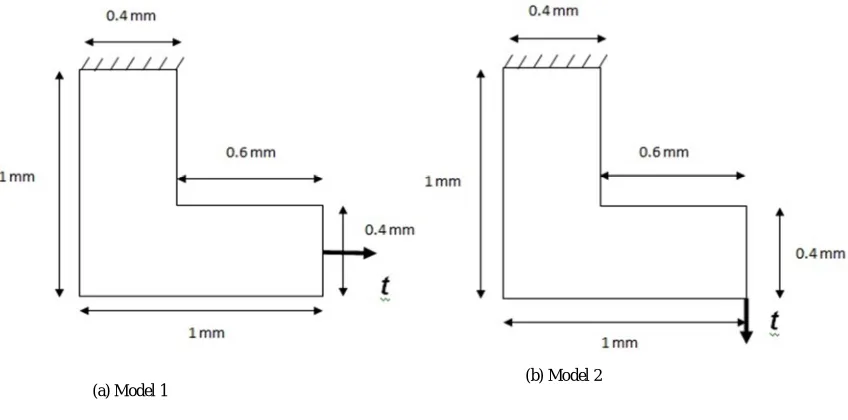
[image:3.612.102.526.471.681.2]In the present investigation, the dimensions of the L-shaped bracket and the boundary conditions are in accordance with those in the work of Qi Xia et al. [2012]. The material properties and loads used are given in table I.
TABLE I
Young’s Modulus Poisson’s ratio Load (N)
1 0.3 1
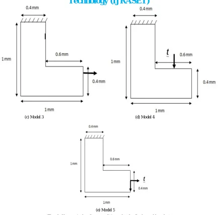
The point load is applied at different locations on the L-shape beam. The beam is under a state of plane stress and is supported at the top by a fixed support .The edge element length is 0.025. The load applied is of 1N. The following figures show the L-shaped beam under various loading conditions.
(a) Model 1
Technology (IJRASET)
Fig. 2 Change in loading conditions for the L-shaped bracket
III. RESULTSANDDISCUSSION
The final compliance values and von Mises stress at different loading conditions for the L-shaped bracket is shown in table II. The volume usage fraction is 0.5.
TABLE III
FINAL COMPLIANCE VALUE AND VON MISES STRESS AT DIFFERENT LOADING CONDITIONS FOR L-SHAPED BRACKET
Loading Compliance Iterations von Mises
Model 11 50.537 21 64.238
Model 12 171.80 26 235.391
Model 13 36.028 24 61.92
(c) Model 3 (d) Model 4
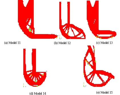
loading conditions. Figure 3 shows the optimal topology for all the five models under different loading conditions.
[image:5.612.71.492.109.441.2]
Fig. 3 Optimal Shapes Obtained by ANSYS Based OC for Different Loading Conditions
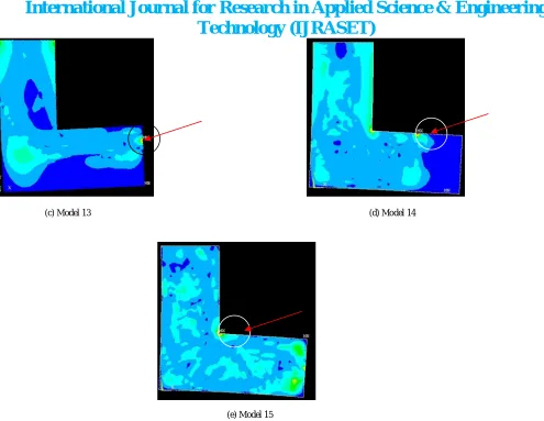
The maximum von Mises stresses at different loading conditions are shown in table II while figure 4 shows the location of the point where maximum stress occurs. The maximum stress occurs when the beam is subjected to the loading condition as shown in model 2.
(a) Model 11 (b) Model 12 (c) Model 13
(d) Model 14 (e) Model 15
Technology (IJRASET)
[image:6.612.46.541.42.425.2]
Fig. 4 Location of maximum von Mises stresses at different loading conditions with arrow pointing at maximum stress point
IV. CONCLUSIONS
In this paper, we presented a optimal criterion solution to the stress based topology optimization. The maximum stress magnitude and location got varied as the loading conditions are changed. The effect of loading conditions on topology and compliance is also studied and different optimal shapes were obtained when the loading conditions were changed. . The one loaded as shown in model 2 has the highest compliance value among all the five used loading conditions. The maximum stress occurs when the beam is subjected to the loading condition as shown in model 2.
REFERENCES
[1] Huayang Xu ,Liwen Guan, Xiang Chen, Liping Wang, 2013. Guide-Weight method for topology optimization of continuum structures including body forces . Finite Elements in Analysis and Design 75:38–.49.
[2] Matteo Bruggi , Carlo Cinquini, 2009. An alternative truly-mixed formulation to solve pressure load problems in topology optimization. Comput. Methods Appl. Mech. Engrg. 198:1500–1512.
[3] Qi Xia , Tielin Shi , Shiyuan Liu and Michael Yu Wang, 2012. A level set solution to the stress-based structural shape and topology optimization. Computers and Structures 90–91.
[4] Qi Xia, Michael Yu Wang and Tielin Shi, 2014. A level set method for shape and topology optimization of both structure and support of continuum structures. Comput. Methods Appl. Mech. Engrg. 272:340–353.
[5] Ruben Ansola, Javier Canales, Jose A. Tarrago, John Rasmusse, 2002. An integrated approach for shape and topology optimization of shell structures. Computers and Structures 449–458.
[6] X. Huang , Y.M. Xie, 2011. Evolutionary topology optimization of continuum structures including design-dependent self-weight loads. Finite Elements in
(c) Model 13 (d) Model 14