Technology (IJRASET)
Design and Development of Casting by Simulation
Technique for Yield Improvement in Foundry
Industry
Swaroop S. Magdum1, Baliram R. Jadhav2
1
Student, M.Tech, Department of Mechanical Engineering, RIT, Sakharale, Sangli, Maharashtra, India.
2
Associate professor, Department of Mechanical Engineering, RIT, Sakharale, Sangli, Maharashtra, India.
Abstract - In process of casting various critical shapes are manufactured and that involves creating a cavity inside a sand mould and then pouring the molten metal directly into the mould cavity. Casting is versatile process so that it is used for the mass production. The components are of very large as well as very small shape with very critical shape involves in it. Gating system is most important part in casting process. Having correct gating system is very important in the casting process for the sound, defects free casting and higher yield. Casting process is very uncertain process even in a completely controlled process defects are found which challenges to find the causes of casting defects. For the development of the casting processes simulation techniques are used in the AutoCAST simulation software. In the simulation technique the gating system is designed numerically and by that dimensions the 3D model of the gating and cavity is drawn, that model is used for virtual casting in that process by that simulation technique trial and error method the optimized gating system finalized. After the simulation process the finalized designed gating system is implemented on the pattern and the sample casting is taken to validate the result of the simulation technique.
Keywords - casting simulation, 3D CAD modeling, gating system, sound casting, pressure die casting.
I. INTRODUCTION
In automobile industries many parts used are of different shapes and they are difficult to manufacture so the casting process is always used in the manufacturing of the automobile products. Casting is a very versatile process and capable of being used in mass production. Foundry is mother industry. In casting process lots of research has been carried out in foundry technology, but yet trial and error method used for designing the gating system, it is time consuming and costly process, so the material utilization, energy utilization, and other resources utilization is very difficult in foundry industries. Many critical shapes are manufactured in foundry by casting process, because of critical shapes present many defects arise in casting while directional solidification. Even in a completely controlled process, defects are found out. So for the good directional solidification proper designing of gating system is very important to provide metal in liquid form to the casting cavity. The gating system should be designed properly because oversized gating system leads to lower yield of the casting.
A. Problem definition
In old process of casting the gating system is finalized by the trial and error method, but this process is time consuming and costly. Finalizing the gating system will be after the four or five iterations the casting process is carried out. After that if the casting is sound and of good quality but the yield is lower and because of that the material is wasted, time consumed highly. So the improvement in designing of gating system is very important.
This process is carried out for the manufacturing of 3 cylinder manifold. The 3 cylinder manifold is having much difference in the thickness. Some area is thick and some area is thin. So designing the gating system by trial and error method is very time consuming and not so effective.
B. Literature survey
Technology (IJRASET)
wasted in the trial and error method. In the casting simulation software AutoCAST the virtual casting is done.
B. H. Hu, et al. [2] proposed that well designed gating and runner system is important to give good quality die casting through providing a homogenous mould filling pattern. The cost effective tool numerically designing of gating is used to design the gating and runner system to analyze visibly the mould filling process.
S.H. Wu, et al. [6] the designer design the gating system by calculating related parameters and start modeling the geometries of gating elements from scratch. In trial and error process of designing gating is time consuming process. So in this computer-aided parametric design is used to address the problem of the automatic generation of the gating elements and to utilize design evaluation that helps predict and evaluate the design conditions.
Jean Kor, et al. [5] proposed that due to the lack of existing theoretical procedures to following designing the gating system so the design process is normally carried out on a trial-and-error basis. In this paper, the casting design is first formulated as a multi-objective optimization problem with conflicting multi-objectives and a complex search space.
ΙΙ. METHODOLOGY
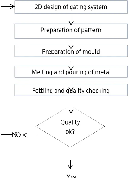
In conventional gating optimization process includes actual sample casting trials in which gating system, location of gating system etc. are required to be changed in each iteration which is associated with machining cost, tooling cost, modification cost, melting cost, fettling and transportation cost as well as energy, materials, time are wasted in each sample casting until and unless the required results are obtained. Hence optimization using conventional process is costly, complex and time consuming.
NO
[image:3.612.39.252.335.629.2]Yes
Fig. 1 conventional casting process
To improve the casting process and improve yield of the casting process have to use new technique. In new method of casting the gating system numerically designing by using the formulas and ratios of sprue: runner bar: ingates. After the numerical designing by using the 3d cad modeling software the model of cavity and gating system is designed and that model is saved in .stl format and loaded in the AutoCAST software and virtually casting process pouring is done that process is called as casting simulation. After
Preparation of pattern
Preparation of mould 2D design of gating system
Melting and pouring of metal
Fettling and quality checking
Technology (IJRASET)
that in that software we get the information about the gating system that is the gating system is working properly or not is there any defects present in casting. By using the casting simulation the saving of material and saving of time is also done.
The trial and error method is minimized of taking sample casting. And that trial and error method is adopted in the virtual casting. The trial and error is done in virtual casting till the optimized gating system is found. So as per that gating the oversized gating is not taken and the yield is improved in casting process.
NO
[image:4.612.40.247.163.361.2]Yes
Fig. 2 virtual casting process
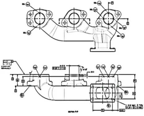
For the development of the casting process and improvement in yield the 3 cylinder manifold is chosen because it is having the high thickness variation from 3.5mm to 10mm the functional design is shown in the following image.
Fig. 3 Detail drawing 3 cylinder manifold A. Analysis of old gating system
In the mould box four cavities are present and to fill those four cavities of the mould the old gating system was connected as shown in the following fig.
Quality ok?
Draw 3D design of gating system
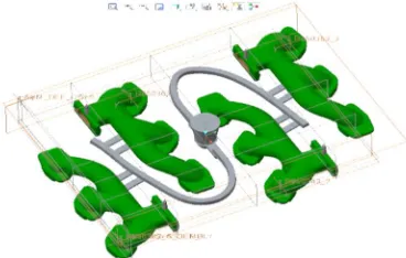
[image:4.612.187.420.432.619.2]Technology (IJRASET)
Fig. 4 3D CAD model of casting assembly with old gating design
In old gating system the parts are present are runner bar and ingate. Runner bar is having cross section area of the rhombus having dimension 14mm x 22mm x 20mm and the ingates cross section area is rectangle having dimension 14mm x 5mm.
[image:5.612.186.429.352.467.2]To improve the yield and minimize the defects and to design the new gating system the simulation of the old gating system was taken and the following results were found. The following image shows the solidification of metal and that figure shows the hot spot region.
Fig. 5 Solidification result with old gating system
By observing the above image hot spot regions are present in the mould cavity. The various colors for the analysis of state of metal and temperatures used are as follows: Blue indicates early freezing region, red – In phase of solidification, white – Hot region, and yellow – Hot spot. Then after virtual casting the defects present are shown in the following diagram.
[image:5.612.184.431.552.692.2]Technology (IJRASET)
The above diagram shows the defect shrinkage porosity which present in the old design of the gating system. For the dark red color macro porosity defect is shown and for faint red color the micro porosity defect is present. To minimize that defect and to improve the yield modification in the gating system is required.
B. Design new modified gating system
Well-designed gating and runner system is important to give good quality die casting through providing a homogenous mould filling pattern [2].
In the designing of the modified gating is done numerically as per the ratio present sprue: runner bar: ingates. The ratios used are 2: 1: 1 and 2: 1.1: 1.1. In phase of designing the gating system first the choke area is calculated in this casting process the choke area is present in sprue. After finding the choke area the further runner bar and ingates dimensions are found out.
Choke area: A =
H= h -
A= 787.55
By calculation the choke area is = 787.55 = 788
Gating ratio no. 1
2 : 1 : 1
So it is as follows
788: 394: 394
As per the ratio got the runner bar which having cross section area is rhombus and the ingates which is having cross sectional area is square and rectangle are calculated.
C. Making 3D cad model and simulation of gating design
For optimizing of the gating system gating is drawn in directly in the AutoCAST software after importing the designed pattern in .stl format or designing the gating system in the 3D designing software and importing it in AutoCAST software and simulates it [3]. But in this case the gating system is designed in the Creo parametric software because in the designing software the smoothness and perfection in design is higher. And the curvature and modified design got by this method.
After designing the gating system numerically the 3D cad model of that model and gating system is drawn in the Creo Parametric software and saved in .stl format, and it is simulated using e-foundry simulation lab. After simulation the image of solidification of the casting got, the results will appear as 3D color image of temperatures inside casting at the end of solidification. From the image idea regarding temperatures inside casting can be achieved. The various colors for the analysis of state of metal and temperatures used are as follows: Blue indicates early freezing region, red – In phase of solidification, white – Hot region, and yellow – Hot spot.
Technology (IJRASET)
Table – 1 Modified gating systems designed numericallyGating Gating
ratio
Simulation result Proposed
yield
Design 1 2:1:1 Chance of micro
porosity and
shrinkage at thick section of casting.
84.00%
Design 2 2:1:1 No chance of micro
porosity in casting
of 3 cylinder
manifold.
84.25%
Design 3 2:1.1:1.1 No chance of micro
porosity in casting
of 3 cylinder
manifold.
84.59%
For optimize the gating system three models are generated and in between that one object is selected for the full simulation which is having good yield and lower chances of the defects present after casting.
[image:7.612.209.393.384.501.2]The 3D CAD models of casting with the modified gating system designs and 3D simulated solidification results of each design is shown in following images.
Fig. 7 3D CAD model of casting assembly with modified gating design
[image:7.612.185.430.565.692.2]By uploading the 3D model of the modified gating system the solidification is shown in the following image and in that the hot spot region is shown.
Technology (IJRASET)
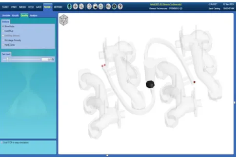
[image:8.612.187.432.111.275.2]After observing the solidification image the molten metal is poured virtually in that 3D model of the mould cavity. After pouring for checking the quality of the casting the defects are observed and that defects are shown in following image.
Fig. 9 Simulation results of shrinkage porosity of modified gating
The above image shows the defects are present in the casting. The defects are present in the gating system so that the after fettling the gating system will be cut off from actual casting so the modified design of the gating system is correct for the moulding cavity.
By the above practice it is shown that simulation minimizes the shop floor trial and error practice at the high quality and the high yield.
III. EXPERIMENTATION AND YIELD CALCULATION
By the results got from the simulation technique the sample castings are taken for the proposed designed gating system for validation of the simulated design.
A. Actual experimentation
From the modified design of the gating system the gating system is generated of the wood. That gating system is attached to the match plate pattern of the 3 cylinder manifold. After the all attachments are done the pilot castings are taken for several batches and the results are observed after fettling operation, like checking of quality and yield calculation.
For the pilot casting the molten metal is poured is of 220 grade and it is having temperature of 1380°c to 1420°c. For every batch the 20 number of castings are taken and after the pouring the casting is kept for cooling purpose and after that the fettling is done and after all this the calculation of yield and the quality of casting is checked. For calculation of the yield and checking the quality of the casting the casting is randomly chosen between the batches.
The following table shows the pilot casting batches are taken.
Table -2 Batches of the pilot casting
Sr. no.
Batch No of sample
casting
No. of
defects found
1 A 10 1
2 B 10 0
3 C 20 2
4 D 20 1
Technology (IJRASET)
After pilot casting the yield is calculated by the following method the formula for calculation of yield is given below.
Yield= × 100
The yield of the old gating system was 73.33%. After simulation the yield is calculated virtually for the three modified design of the gating system was 84% to 85%. But after pilot casting done the yield calculated was up to 80% to 81%. The difference in the yield is present because the virtual casting is ideal process and in the actual process some different working conditions are present, like very small miss match is present in parting line.
IV. CONCLUSION
The non-value added and the time consuming process like optimising the gating system by trial and error method will be minimised by using the simulation technique by using the 3D designing software and casting simulation software AutoCAST X1 flow plus. So by using this technique the wastage of the resources is minimized which is used in trial and error method. In addition, the optimization of quality and higher yield implies higher value-addition and lower production cost, improving the margins. For widespread application simulation programs are faster, dependable, and user friendly. By using this simulation program the results shown like defects and the hot spot region are likely to be same in most of the times. So this technique is very faster and less time consuming and easy to handle so that small scale foundries also can take benefit of this technique for development purpose.
V. ACKNOWLEDGEMENT
I would like to express my thanks to Ashta liners Pvt. Ltd. Ashta for allowing me to work on this dissertation, and I would like to express my thanks to Prof. B. R. Jadhav sir for his whole hearted co-operation and valuable suggestions and technical guidance, as well as and I would like to express my thanks to Dr. V. D. Shinde sir for his valuable suggestions and technical guidance related the software AutoCAST.
REFERENCES
[1] Kermanpur, Sh. Mahmoudi, A. Hajipour,“Numerical simulation of metal flow and solidification in the multi-cavity casting moulds of automotive components”, journal of materials processing technology,206, 62–68,2008.
[2] B.H. Hu, K.K. Tong, X.P. Niu, I. Pinwill, “Design and optimization of runner and gating systems for the die casting of thin-walled magnesium telecommunication parts through numerical simulation”, Journal of Materials Processing Technology, 128-133, 2000.
[3] Dr. B. Ravi, “Computer-aided Casting Method Design, Simulation and Optimization” Silver Jubilee Seminar Institute of Indian Foundrymen (Indore Chapter), Indore march 2008
[4] Dr. B. Ravi, “Bridging the Digital Divide in Casting Simulation Technology” 57th INDIAN FOUNDRY CONGRESS, Kolkata, 2009.
[5] E. Fu-Yuan Hsu, Mark R. Jolly, John Campbell, “A multiple-gate runner system for gravity casting”, Journal of Materials Processing Technology, 5736–5750, 2009.
[6] Jean Kor, Xiang Chen, and Henry Hu, “Multi-Objective Optimal Gating and Riser Design for Metal-Casting”,IEEE International Symposium on Intelligent Control, 2009
[7] S.H. Wu, J.Y.H. Fuh, K.S. Lee, “Semi-automated parametric design of gating systems for die-casting die”, Computers & Industrial Engineering, 222–232, 2007.
[8] SarojraniPattnaik, D. Benny Karunakar∗, P.K. Jha, “Developments in investment casting process—A review”,Journal of Materials Processing Technology,2332– 2348,2012.
[9] T. Nandi, R.Behera, S kayal, A Chanda, G.Sutradhar, “Study on Solidification Behavior of Aluminium alloy (LM6) Castings by using Computer aided Simulation software” international Journal of Engineering Research and Applications Vol. 1, Issue 2, 157-164
[10] Uday A. Dabade, Rahul C. Bhedasgaonkar, “Casting Defect Analysis using Design of Experiments (DOE) and Computer Aided Casting Simulation Technique”, Forty Sixth CIRP Conference on Manufacturing Systems 2013,Procedia CIRP 7,616 –621,2013.
[11] V.V.Mane, Amit Sata, M. Y. Khire, “New Approach to Casting Defects Classification and Analysis Supported by Simulation”