Regenerative Braking and Speed Reversal of DC
Motor and Speed Control by DSP
Mr. Snehal Dubey1, Dr. Harikumar Naidu2, Mr. Pratik Ghutke3 1
M.Tech Student , TGPCET, RTMNU, Nagpur 2
H.O.D, Dept. of Electrical Engg. , TGPCET. 3
Guide, Asst. Professor, TGPCET.
Abstract: The speed control of DC Motor using the low cost new generation 18F25K20 digital signal processor (DSP) when the error signal getting the DSP will change the duty cycle of the PWM(on the basis of mark space ratio). The closed loop control is analyzed using transfer function techniques and necessary of current loop is demonstrated. The PWM pulse is generated by the DSP and given to the MOSFET. This control techniques is provide better stability and faster control operation in the presence of disturbances and variation in load. We can also control the speed of DC Motor in both directions by using dual converter. This method will have high accuracy. Each loop will have separate PID Controller.
I. INTRODUCTION
DC Motor and their control drives will play very vital role in various industry applications, such as electrical vehicles, steel rolling mills, electric cranes, electric traction in Indian railway, robotic manipulators and also for some commercial application like home appliances, washers, and driers and compressor. Apart from all such application, DC Motor drives also used in wind energy, which is a most important source of renewable energy.
There are many power electronics drive based control technique is available for the speed control of DC Motor.
The basic function of the variable speed drive is to control the flow of energy from the mains to process. Energy is supplied to the process through the motor shaft.to control the flow of energy we must control the two physical quantities i.e. torque and speed. The Speed control of DC Motor are simpler and less expensive than other type of motors and speed control over a large range both below and above the rated speed can be easily achieved.
The use of Digital Signal Processor ( DSP) permitted the fast efficient and accurate speed control of DC Motor.DSP 18F25K20 from Texas instrument are currently used for wide range of control application and communication. The DSP based system are readily programmed for the other applications.
DSP processor will take speed of motor as a feedback signal according to the difference between set point of the speed and the present speed finally it will change the duty cycle of the base drive signal. This is given as input to the buck converter. The buck converter is basically a step down converter and will supply the input to the DC Motor as per input duty cycle.
As DSP provides easy implementation of complex control with greater accuracy and speed of response, It is becoming popular in industrial drive system.DSP based PID controller has been provided the speed control of DC Motor.
II. BUCK CONVERTER AND DC MOTOR
The buck converter is a step down converter. DC to DC converter are nonlinear due to switching operation. The regulation is normally achieved by mark space ratio at fixed frequency. MOSFET is the is the switching device which has low loss with high frequency.
The buck converter is used to give the regulated DC supply to the DC Motor according to the duty cycle of input.
[image:2.612.129.484.618.720.2]Volume 5 Issue VII, July 2017- Available at www.ijraset.com
III. DC MOTORS MODELING AND CONTROL
The closed-loop speed control system in this study consists of a separately excited DC motor, a pulse width modulation at constant frequency, chopper, and proportional integral derivative type (PID) for speed and current controller that design using Ziegler-Nichols method. The transfer function which was found it in the previous section is used in MATLAB Program with multiple closed loop control system to tune the parameters of the PID controller. The closed-loop control of the motor has basically two feedback loops. The outer loop is a speed feedback loop and the inner loop is the current feedback loop. The controller used in these loops are both of the PID type. The parameters of PID controller which was found it is used in the Power System Block set (P.S.B) library to build the model of the system. The speed controller output is fed to a current limiter that produces controller signal to the current and this implement the reference for the current controller. The output of the current controller is the input to the uniform pulse width modulated (PWM) generator that
controls the motor input voltage [6].
The protees simulation model of the closed loop control system of the DC motor.
Figure (2) model of a dc shunt motor speed control .
IV. FIRING CIRCUIT WITH GATE DRIVER
[image:3.612.175.438.259.528.2]circuit consists of three stages, buffer circuit, Opt coupler circuit and matching circuit. The practical isolated firing circuit is shown in Fig.(3).
.
Fig(3) Schematic arrangement of firing circuit with gate driver.
V. DIGITAL SIGNAL PROCESSOR
18F25K20) The 18F25K20 DSP has many special features for the control applications. It has Event Manager that is specially designed for the motor control and motion control applications [4]. The general-purpose Timer3 in EVB (Event Manager B) is used in continuous up/down count mode for the symmetric PWM generation. Timers have associated compare registers which are used to write the calculated duty ratio values. These values then get compared with the timer counter value in order to generate the PWM output [6].The code development is carried out through an application suite called Code Composer StudioTM (CCS). The Code Composer Studio (CCS) provides an integrated development environment (IDE) to incorporate the software tool which is fully compatible and enables the engineers to simplify the source code. It has graphical capabilities and supports real-time debugging. The 12-bit ADC module has 16 channels, configurable as two independent 8-channel modules to service event managers A and B. The two independent 8-channel modules can be cascaded to form a 16-channel module. Although there are multiple input channels and two sequencers, there is only one converter in the ADC module. Fig (4) shows the block diagram of the F2812 ADC module. The ADC of DSP could be triggered by the software, EVA/B or the external pins. In this paper the DSP platform, is set up the ADC trigger by the GPtimer1 (general-purpose timer one) of EVA that is set to continuous up count mode, whose frequency is supposed to be equal to the sampling frequency of the ADC. The Block diagram of the EVA module of 18F25K20 is shown in Fig (5). The tachogenerator and reference voltages are connected to ADCINB0 and ADCINB1 respectively. Since the SOC is started by the GPTimer1, and once the conversion is finished, the EOC (end of conversion) interrupt is triggered, and then the ADC interrupt routine is called in the program. In ADC interrupt routine, DSP reads the sample results from the ADC result registers (ADCRESULT0 and ADCRESULT1).
[image:4.612.212.406.128.272.2] [image:4.612.183.426.533.701.2]Volume 5 Issue VII, July 2017- Available at www.ijraset.com
Figure (5) Block diagram of the 18F25K20.
VI. EXPERIMENTAL RESULTS
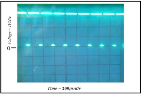
[image:5.612.174.443.96.637.2]Figure (6) pulses output signal from DSP Kit .
Fig.(7) shows the armature current of the DC motor with closed loop control system, from this Figure, it is noted that the armature current does not exceed the rated current of DC motor.
Figure (7) Armature current of the DC motor.
Fig. (8) shows the practical step speed response of DC motor with speed rising from zero to a predetermined speed of 1375 rpm shown by the NI-PCI-6023E data acquisition card (DAQ) with 1000 sample/second. It can be seen that a steady raise is achieved with almost 2.8% overshoot and then the speed settles at required speed.
[image:6.612.183.432.93.258.2] [image:6.612.180.435.313.484.2] [image:6.612.182.433.548.709.2]Volume 5 Issue VII, July 2017- Available at www.ijraset.com
VII. CONCLUSION
The closed loop speed control system has been experimented, and the results were obtained by connecting DC motor as a load to the BUCK converter which is controlled by 18F25K20 DSP. All the circuits were design and simulated using protees program. Simulation and experimental results demonstrated the validity of the system and showed that the DSP is reliable instrument to control the motor. The system shows the applicability to different sizes of the motors and capable of controlling the speed of the motors with very high precision.
REFERENCES
[1] Moleykutty George, "Speed Control of Separately Excited DC Motor". American Journal of Applied Sciences, ISSN 1546-9239, 2008
[2] Jianxin Tang, "PID Controller Using the TMS320C31 DSK with on-Line Parameter Adjustment for Real-Time DC Motor Speed and Position Control", IEEE ISIE 2001
[3] K. Sundareswaran and M. Vasu, “Genetic Tuning of PI controller for Speed Control of DC Motor Drive”, IEEE vol.2 ,PP. 521-525, 2000
[4] S. G .Kadwane, S. P. Vepa, B. M. Karan and T. Ghose, “Converter Based DC Motor Speed Control Using TMS320LF2407A DSK”, IEEE- ICIEA, PP. 1-5, 2006