- - --'--J-i•-
PUBLICATION 244a Change Notice 1 February28, 1963
1604-A COMPUTER
Input/Output Specifications
1. The following pages of this publication contain errors and should be corrected as indicated:
Page 7 -- Change time intervals D and G to:
D - Minimum time 7. 4 jisec, maximum time 50.8 isec G - Minimum time 1. 4 usec, maximum time 2. 8 psec Page 9 -- Change time interval B and E to:
B - Minimum time 5. 8 psec, maximum time 49. 2 psec E - Minimum time 1. 4 isec, maximum time 2. 8 jsec
2. Page B-1 of this publication has been revised and supersedes the original page B-1.
APPENDIX B BUFFER CONTROL
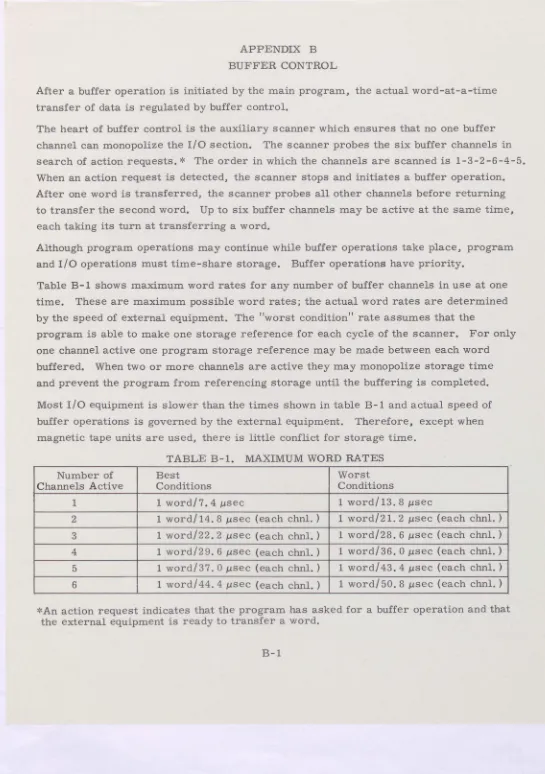
After a buffer Operation is initiated by the main program, the actual word-at-a-time transfer of data is regulated by buffer control.
The heart of buffer control is the auxiliary scanner which ensures that no one buffer channel can monopolize the I/O section. The scanner probes the six buffer channels in search of action requests. * The order in which the channels are scanned is 1-3-2-6-4-5. When an action request is detected, the scanner stops and initiates a buffer operation. After one word is transferred, the scanner probes all other channels before returning to transfer the second word. Up to six buffer channels may be active at the same time, each taking its turn at transferring a word.
[image:3.642.57.602.26.800.2]Although program operations may continue while buffer Operations take place, program and I/O operations must time-share storage. Buffer Operations have priority.
Table B- 1 shows maximum word rates for any number of buffer channels in use at one time. These are maximum possible word rates; the actual word rates are determined by the speed of external equipment. The "worst condition" rate assumes that the
program is able to make one storage reference for each cycle of the scanner. For only one channel active one program storage reference may be made between each word buffered. When two or more channels are active they may monopolize storage time and prevent the program from referencing storage until the buffering is completed.
Most I/O equipment is siower than the times shown in table B-1 and actual speed of buffer Operations is governed by the external equipment. Therefore, except when magnetic tape units are used, there is little conflict for storage time.
TABLE B-1. MAXIMUM WORD RATES Number of
Channels Active Best Conditions Worst Conditions
1 1 word/7.4 bisec 1 word/l3.8 lasec
2 1 word/14.8 jisec (each chnl.) 1 word/21.2 psec (each chnl.) 3 1 word/22. 2 zsec (each chnl.) 1 word/28. 6 psec (each chnl.) 4 1 word/29. 6 !2sec (each chnl.) 1 word/36. 0 psec (each chnl.) 5 1 word/37. 0 isec (each chnl.) 1 word/43. 4 jisec (each chnl.) 6 1 word/44. 4 psec (each chnl.) 1 word/50. 8 psec (each chnl.)
CONTROL DATA
1604-A COMPUTER
RECORD OF CHANGE NOTICES
C. N. NO. DATE DATE INITIALS REMARKS ORIGINATED ENTERED
Minor Revision (February, 1963) Address comments concerning this This edition, publication 244a, is a
minor revision but does not obsolete publication 244. Pages changed in publication 244a are marked by a dat an the top outside corner.
01963, Control Dato Corporotion
manual to:
Control Data Corporation
Technical Publications Department 501 Park Avenue
CONTENTS
1604A Input/Output Section 1
Buffer 1
Transfer 3
Communication Signals 3
Function Signals 3
Data Signals 6
Input to Computer 6
Output from Computer 8
Summary Listing 10
Cabling 13
Communicatjon 13
Power 13
APPENDLXES
A Communication Circuits A1
B Auxiliary Scanner B1
FIGURES
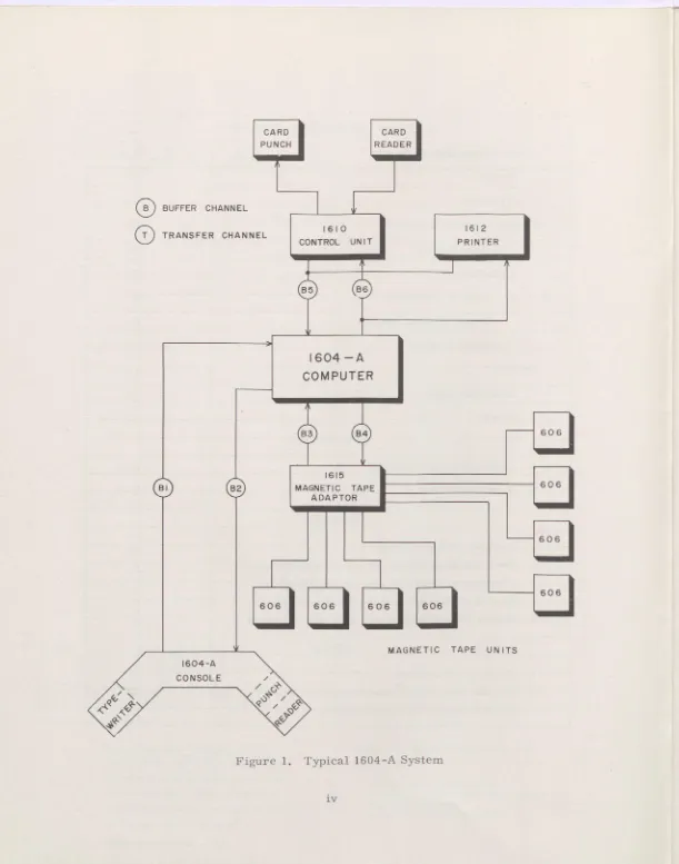
1 Typical 1604A System iv
2 Overall Logic Diagram Input/Output Section 2 3 Function or Sense Ready Timing Diagram 5 4 Input Data Ready/Resume Timing Diagram 7 5 Output Data Ready/Resume Timing Diagram 9
TABLES
1 Cable Identification 14
2 Pin Assignments, Communication Cables 15
This specification contains information necessary to attach external equipment to the CONTROL DATA 1604-A computer either directly or indirectly (through such devices as the 1615 magnetic tape adapter, 1608 control unit or 1610 card control unit). A typical 1604-A system is shown in figure 1.
1604-A INPUT/OUTPUT SECTION
The 1604-A computer communicates with external equipment via six buffer channels and a single transfer channe1 The buffer channels provide for the normal exchange of data with several equipments concurrently. Exchange of data on buffer channels is program initiated but is carried out independently by the buffer control section. The transfer channel provides for very high speed exchange of data under direct program
control.
BUFFER
Buffer operation is initiated by the main computer program and continues at a rate determined by the external equipment (see appendix B). The 1604-A can perform buffer operations with three input devices and three output devices concurrently. Each device determines the rate of its own data transmission and provides its own means of internal control. Buffer operations are started by the External Function (EXF 74) instruction.
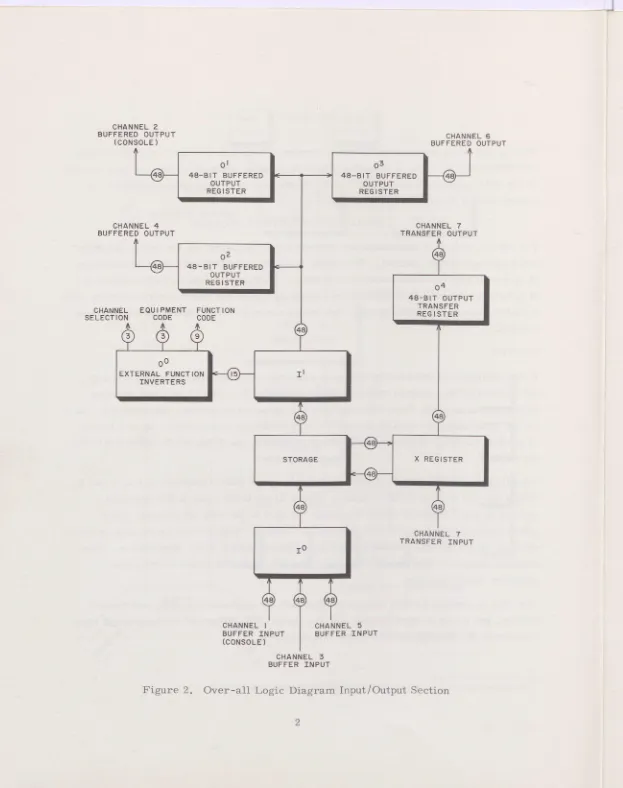
Input buffer channels are numbered 1, 3 and 5; output buffer channels are 2, 4 and 6. Within the I/O section of the computer (figure 2) the three input buffer channels connect to the 10 register which transmits the data to the storage section. Each output channel is associated with a specific register. Data is held on the line until the external equipment has received and acknowledged receipt of the information. Each external equipment has an output register for sending information to one of the computer input channels.
The 1604-A storage section is connected to both the arithmetic section and the i/O section, but it can be used by only one at a time. The buffer and main program must time share the storage section of the computer.
CHANNEL 2 BUFFERED OUTPUT
(CONSOLE)
01
48-BIT BUFFERED OUTPUT REGISTER
CHANNEL 4 BUFFERED OUTPUT
0 2 48-BIT BUFFERED
OUTPUT REGISTER
CHANNEL EQUIPMENT FUNCTION
SELECTION CODE CODE
CI-IANNEL 6 BUFFERED OUTPUT
48-BIT BUFFERED OUTPUT REGISTER
CHANNEL 7 TRANSFER OUTPUT
04
48-BIT OUTPUT TRANSFER REG 1 STER
0 0
EXTERNAL FUNCT ION II
INVERTERS
STORAGE X REGISTER
CHANNEL 7 TRANSFER INPUT iO
CHANNEL 1 CHANNEL 5
BUFFER INPUT 8UFFER INPUT
(CONSOLE)
[image:9.642.18.641.14.802.2]CHANNEL 3 BUFFER INPUT
Buffer channels are grouped for connecting to external equipment as foliows:
Channel 1 - Buffer input
2 - Buffer output
3 - Buffer input 4 - Buffer output
5 - Buffer input 6 - Buffer output
TRANSFER
The transfer mode of communication is initiated by the program and program
operations stop while the transfer takes place. A block of words is transmitted one word at a time and the next program instruction is executed only after the last werd of the block has been transmitted. (Buffer mode can occur concurrently with a transfer instruction if the buffer is initiated before the transfer instruction. ) Input transfer of a block of information is performed by instruction 62, output transfer by
instruction 63.
The maximum transfer rate is approximately one word every 5 isec. The transfer channel, consisting of input lines and output lines, connects to the X register.
COMMUNICATION SIGNALS
Communication with external equipment is established with function signals and data signals. Function signals select an external equipment and direct it to perform some operation. Data signals carry the information to be exchanged. All function and data signals on the input and output lines are voltage levels representing a binary "1" or "0". Pulse representation is used internally in the computer but not on the input/output lines.
FUNCTION SIGNALS
The number of equipments with which the 1604-A can communicate is limited by electrical considerations rather than by the number of I/O channels available. Several equipments can be linked to the computer on the same I/O channel by
r
EXF 74.0 Selects an external equipment and places it in a mode of operation.
EXF 74. 7 ---Senses conditions such as ready or error in an external equipment.
The five octal digits of the base execution address are interpreted as shown below: 74. 0 or 74. 7
Channel 1,2 ... 7 Equipment Function Selection Code Selection Code Code
(1604-A translates internally) To equipment on channel designated
The four bw -order octal digits are sent on all function channels (buffer and transfer). The 1604-A buffer control transiates the channel selection digit and sends one of the folbowing control signals to all equipments on the designated channel to albow each to sample the code.
Select Sense
Input Function Ready Input Sense Ready
Output Function Ready Output Sense Ready
The selected equipment does not send a resumo to the computer after an EXF select (74. 0) instruction.
For EXF sense (74. 7) instructions, the external equipment returns a sense response signal to the computer if the sensed condition is present.
Control circuits of all external equipmnts on channel X are cleared hy an EXF 74. OX0000 (channel clear) code.
All external equipments must adequately resynchronize all control signals (signals other than data).
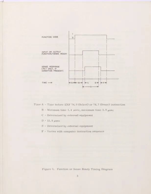
FUNCTION CODE
INPUT OR OUTPUT FUNCTION/SENSE READY
SENSE RESPONSE (747 ONLY, IF
CONDITION PRESENT)
TIME -
Time A - Time before EXF 74. 0 (Selcct) or 74. 7 (Sense) instruction
B Minimum time 1. 4 psec, maximum time 3. 0 tsec
C Determined by external equipment
D - 12. 8 isec
E - Determined by external equipment
[image:12.642.10.627.18.809.2]F - Varies with computer instruction sequence
The sequence is:
The computer executes an EXF 74. 0 or 74. 7 instruction to select an external equipment and the operation.
The computer sends the input or output function/sense ready to allow the external equipment to sample the function lines.
For EXF 74. 7 instructions, the external equipment gates the ready signal with the condition being sensed and sends a sense response Signal if the condition is present.
DATA SIGNALS
Data is transmitted to and from the 1604-A via 48-bit parallel lines. Input equipment with a word length of less than 48 bits must transmit a binary l for the unused high- order bits. Output equipments with word length less than 48 bits need not sense the unused signal lines. (Open lines are recognized as '0' by the computer.
Ready and resume control signals accompany data transmissions. Information sent from external equipment to the computer is associated with input data ready and resume signals; information sent from computer to external equipment is associated with output data ready and resume sigtials. A ready indicates that data is waiting to be sampled. A resume replies to the data sending device that data has been received and should be removed from the line.
Labeling of input and output registers is referred to the pertinent external equipment. For example, data originating in the paper tape reader passes through the reader's output register and is sent to the computer's input register along with an input data ready. Upon receipt of the input data ready the computer stores the information and sends out an input data resume.
Innut to Computer
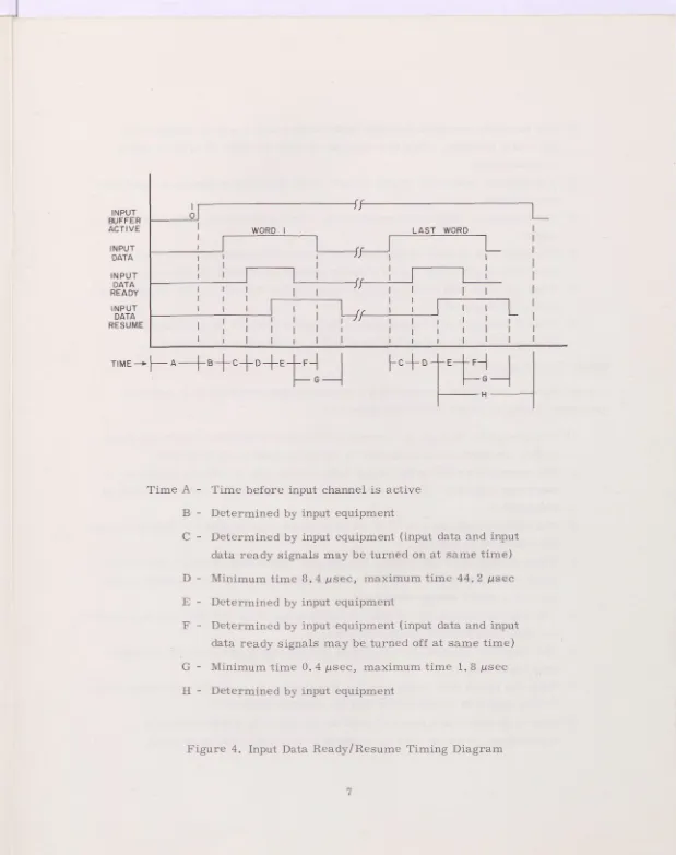
Control signals required in transmitting a word from an external equipment to the computer during an input buffer are as foliows (figure 4):
LAST WORD INPUT
BUFFER ACT IV E
INP(JT DATA
INPUT DATA READY
INPUT DATA RESUME
TIME - I--- A
B_CI
- D
_h
E-
-
I
F
C+DTE
tF
-~
Time A - Time before input channel is active
B - Determined by input equipment
C - Determined by input equipment (input data and input
data ready signals may be turned on at same time)
D - Minimum time 8. 4 jisec, maximum time 44. 2 lisec
E - Determined by input equipment
F - Determined by input equipment (input data and input
data ready signals may be turned off at same time)
G - Minimum time 0. 4 jsec, maximum time 1. 8 /isec
[image:14.642.5.624.18.801.2]H - Determined by input equipment
The computer activates the input buffer active line to signal readiness to start data transfer. This line remains up until the final word of the block is transmitted.
The external equipment places a word on the lines and produces an input data ready signal.
The computer, when it has accepted the word, produces an input data resume signal.
The input data resume signal causes the external equipment to turn off the input data ready Signal and to prepare another input word for the computer. When the input data ready signal is dropped, the computer turns off the input data resume signal.
Steps 3 through 6 are repeated until the entire block of information is transmitted at which time the input buffer active signal is dropped.
Output From Computer
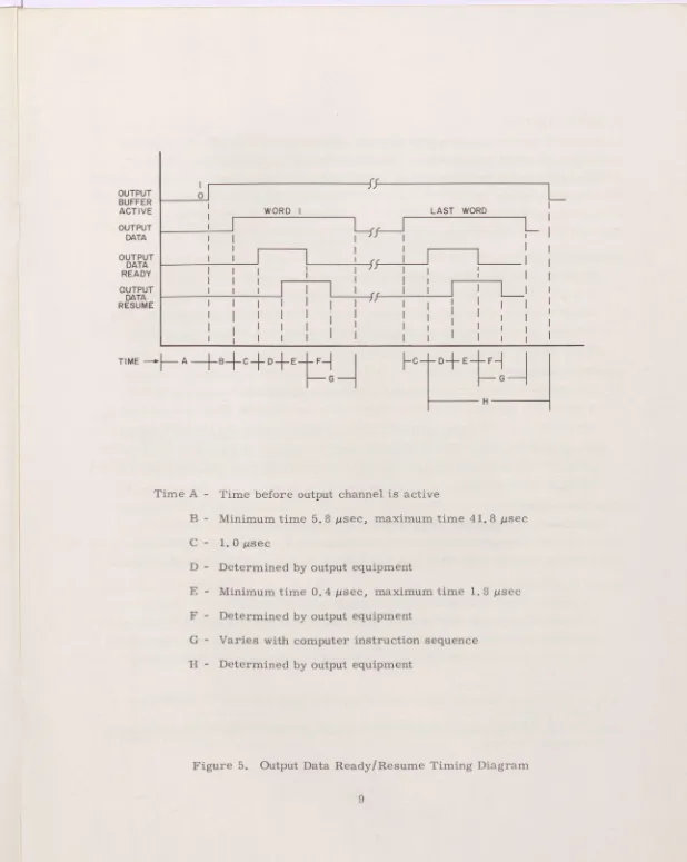
Control signals required in transmitting a word from the computer to an external equipment during an output buffer are (figure 5):
The computer, through the correct combination of external select and sense codes, establishes the equipment to which information is to be sent.
The computer activates the output buffer active line to indicate readiness to start data transfer. This line remains on until the final word of the block is trans mitte d.
The computer places a word in the associated output register. This energizes all data ines in parallel.
When all data lines are stable, the computer generates an output data ready signal which indicates to the external equipment that data is available on the lines in a stable steady-state form.
The external equipment accepts the information at its own rate and then sends an output data resume to the computer.
The computer accepts the output data resume signal and turns off the output data ready signal.
When the output data ready signal is dropped by the computer, the output data resume signal is terminated within the external equipment.
1 ART WOPfl
OUTPUT BUFFER ACTIVE
OUTPUT DATA
OUTPUT DATA READY
OUTPUT DATA RESUME
hH
1 1
TIME---A
l~ G
l__U
l~ G
H
Time A - Time before output channel is active
B - Minimum time 5.8 jsec, maximum time 41. 8 psec
C- 1.0j.sec
D - Determined by output equipment
E - Minimum time 0. 4 psec, maximum time 1. 8 jisec
F - Determined by output equipment
G - Varies with computer instruction sequence
[image:16.642.4.622.20.795.2]H - Determined by output equipment
SUMMARY LISTING
Each cable group contains one input channel, one output channel, one set of function lines, and one set of control lines. There are four such cable groups. Three are identical and contain the pairs of input/output buffer channels 1 and 2, 3 and 4, 5 and 6. The remaining group contains the lines for the transfer channel. The six cables within
a group are always used together and are not separable. The control signals
4
necessary for communicating with the computer are defined below.Input Data Ready*
Originates in external equipment; terminates in computer.
A static 11 signal is produced on this line when information is present in the output register of the external equipment which the computer may sample. The external equipment drops this signal when the input data resume signal is received from the computer.
Input Data Resume*
Originates in Computer; terminates in external equipment.
A static lT Signal is produced on this line by the computer when it has accepted the input word. When an input data resurne signal is received from the computer, the input data ready signal is terminated in the external equipment. Dropping the input data ready signal from the external equipment turns off the input data resume signal at the computer.
Output Data Readye*
Originates in computer; terminates in external equipment.
A static lt signal on this line accompanies each word of output information. This signal is turned off by the output data resume signal from the external equipment.
Output Data Resume'
Originates in externai equipment; terminates in computer.
A static trlH signal on this line indicates that the external equipment has accepted the word of information. This signal turns off the output data ready signal at the computer; this causes the external equipment to drop the output data resume.
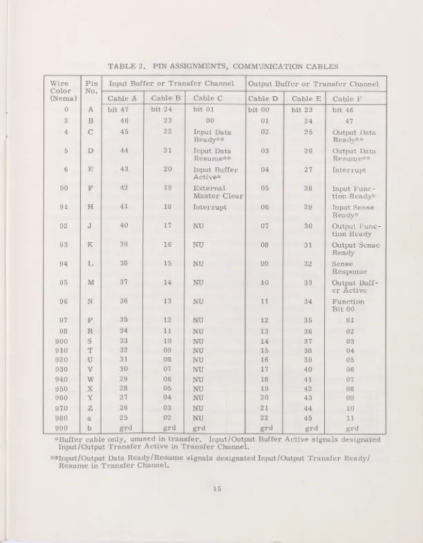
* Input Data Ready/Resume signals are designated Input Transfer Ready/Resume on Transfer Channel.
Input Buffer Active*
Originates in computer; terminates in external equipment.
A static 111 signal is produced on this line whenever the input buffer channel of
the cable group is activated. The signal remains on until the final word of the
4
block is entered in computer storage.Output Buffer Active
Originates in Computer; terminates in external equipment.
A static 1 signal is produced on this line whenever the output buffer channel of the cable group is activated. This signal remains on until the final word of the block is buffered to the external equipment.
External Master Clear
Originates in computer; terminates in external equipment.
A static 111!? signal appears ori this line whenever the clear switch at the 1604-A
console is moved to up position. This signal clears the control functions of all external equipment attached to the cable group.
Interrupt
Originates in external equipment; terminates in computer.
A static 1 Signal is produced on this line whenever the external equipment has assumed an interrupt condition previously selected by the computer. When the signal appears, the computer interrupts the main program and enters a special subroutine which determines the cause of the interruption, takes appropriate action, and returns to the main program. The interrupt line remains energized until the computer removes the interrupt selection or the interrupt condition by: (1) a new
EXF select and (2) EXF select channel X clear (74. OX0000) or (3) a master clear.
Input Function Ready
Originates in Computer; terminates in external equipment.
A static 11111 signal is produced on this line when an external function code is
present on the external function lines for translation by the external equipment. This Signal is automatically dropped after 12. 8 jsec.
Input Sense Ready
Originates in computer; terminates in external equipment.
A static 'l' signal is produced on this line whenever the computer is ready to sense the existence of an input condition within the external equipment. The Signal is automatically dropped after 12. 8 jisec.
Output Function Ready
Originates in computer; terminates in external equipment.
A static 1 signal is produced on this line whenever an external function code is
present on the external function lines for transiation by the external equipment. This signal is automatically dropped after 12.8 jsec.
Output Sense Ready
Originates in computer; terminates in external equipment.
A static signal is produced whenever an external function code is present on the line to sense the existence of an output condition within the external equipment. This signal is automatically dropped after 12.8 psec.
Sense Response
Originates in external equipment; terminates in computer.
A static l signal on this line indicates to the computer the presence of the
condition specified by the upper 11 bits of the 12-bit code sent to external equipment on external function lines. The sense response line is sampled by the computer at the end of the input/output sense ready signal (the computer interprets the inverse
of the sense response received from the external equipment when it sends a code with a lt in the bw-order bit position to the external equipment).
External Function Lines
CABLING
Ecternal equipment is connected to the 1604-A computer System by communication cables and power cables.
COMMIJNICATION
Communication cables are supplied by Control Data Corporation. An equipment may be tied directly to the computer via one of four cable groups which terminate in the computer, or may be indirectly connected to the computer via jumper receptacies provided for this purpose on each of the cabinets in a computer system. The jumper receptacies are wired in parallel with those which connect the cable groups to the computer. Each group contains 6 cables. Table 1 identifies the cable groups.
External equipment to be tied into the computer system without intermediary devices must be equipped with cable receptacies placed so that cables will enter from beneath the floor. Side entry is not used in the 1604-A system. Connector pin assignments are listed in table 2.
General specifications for communication cables:
Length - 50 feet maximum (total for all equipment on one channel).
Connectors - Cable: Amphenol 67-06P-18-24P (or equivalent) each end of cable. Chassis: Amphenol 67 -02E -18 -24S (or equivalent).
Conductors - 48 conduetors (24 twisted pairs). Conductors are #24 stranded. All plug connections are covered by 3/4 inch #14 clear vinyl tubing. Grounding - Pin b carries signal ground. One wire of each twisted pair is
connected to thiS ground at each end of the cable through a ground ring of #20 solid wire. The d-c rsistance of the cable ground does not exceed 0. 5 ohm.
Plotting - Plug connections are potted per Control Data Specification #1100.
POWER
Power for the 1604-A computer System is derived from a 208 vac, 60 cps, 4-wire primary service. This Service is converted to regulated 208 vac, 400 cps, 4-wire service by a motor generator set. The 400 cps and 60 cps power are routed to separate circuit breaker panels at the computer installation and cabled from there to all equipment. Each equipment has separate 400 cps and 60 cps circuit breakers as required.
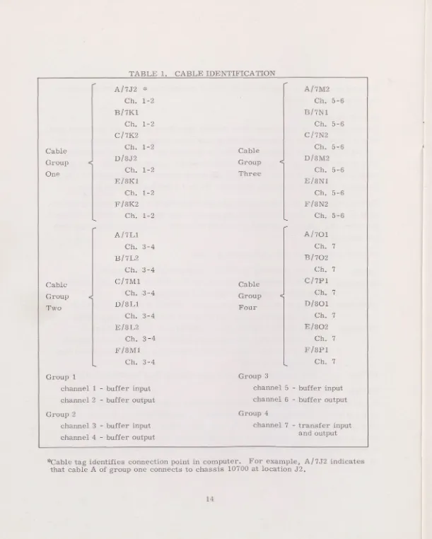
TABLE 1. CABLE IDENTIFICATION
A/7J2
*
A/7M2Ch. 1-2 Ch. 5-6
B/7K1 B/7N1
Ch. 1-2 Ch. 5-6
C/7K2 C/7N2
Cable Ch. 1-2 Cable Ch. 5-6
D/8J2 D/8M2
Group Group
One Ch. 1-2 Three Ch. 5-6
E/8K1 E/8N1
Ch. 1-2 Ch. 5-6
F/8K2 F/8N2
Ch. 1-2 Ch. 5-6
A/7L1 A/701
Ch. 3-4 Ch. 7
B/7L2 B/702
Ch. 3-4 Ch, 7
Cable C/7M1 Cable C/7P1
Group Ch. 3-4 Group Ch. 7
D/8L1 D/801
Two Four
Ch. 3-4 Ch. 7
E/8L2 E/802
Ch. 3-4 Ch. 7
F/8M1 F/8P1
Ch. 3-4 Ch, 7
Group 1 Group 3
channel 1
-
buffer input channel 5-
buffer input channel 2-
buffer output channel 6-
buffer outputGroup 2 Group 4
channel 3
-
buffer input channel 7-
transfer inputchannel 4
-
buffer output and output*Cable tag identifies connection point in computer. For example, A/7J2 indicates that cable A of group one connects to chassis 10700 at location J2.
TABLE 2. PIN ASSIGNMENTS, COMMilNICATION CABLES
Wire Color (Nema)
Pin
No. Input Buffer or Transfer Channel Output Buffer or Transfer Channel Cable A Cable B Cable C Cable D Cable E Cable F 0 A bit 47 bit 24 bit 01 bit 00 bit 23 bit 46
2 B 46 23 00 01 24 47
4 C 45 22 Input Data 02 25 Output IJata
Ready'* Ready'
D 44 21 Input Data 03 26 Output Data
Resume** Resumeee
6 E 43 20 Input Buffer 04 27 Interrupt Active*
90 F 42 19 External 05 28 Input Func-
Master Clear tion Ready
91 H 41 18 Interrupt 06 29 Input Sense
Readye
92 J 40 17 Nil 07 30 Output Fune-
tion Ready
93 K 39 16 NU 08 31 Output Sense
Ready
94 L 38 15 Nil 09 32 Sense
Response
95 M 37 14 NIl 10 33 Output Buff-
er Active
96 N 36 13 Nil 11 34 Function
Bit 00
97 p 35 12 NU 12 35 01
98 R 34 11 Nil 13 36 02
900 S 33 10 Nil 14 37 03
910 T 32 09 Nil 15 38 04
920 U 31 08 Nil 16 39 05
930 V 30 07 Nil 17 40 06
940 W 29 06 Nil 18 41 07
950 X 28 05 Nil 19 42 08
960 Y 27 04 Nil 20 43 09
970 Z 26 03 Nil 21 44 10
980 a 25 02 NU 22 45
fl
990 b grd grd grd grd grd grd
Buffer cable only, unused in transfer. Input/Output Buffer Active signals designated Input/Output Transfer Active in Transfer Channel.
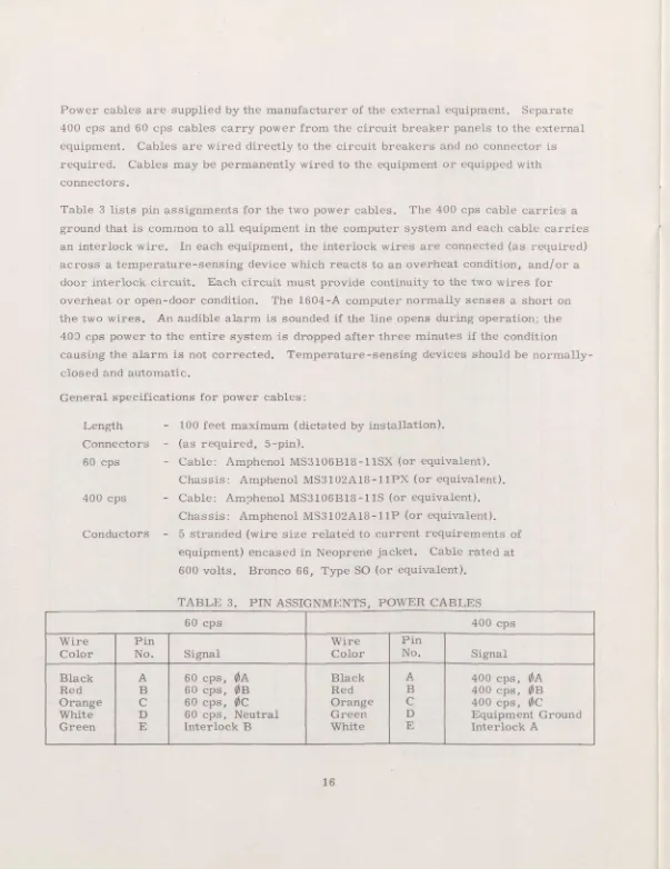
Power cables are supplied by the manufacturer of the external equipment. Separate 400 cps and 60 cps cables carry power from the circuit breaker panels to the external equipment. Cables are wired directly to the circuit breakers and no connector is required. Cables may be permanently wired to the equipment or equipped with connectors.
Table 3 lists pin assignments for the two power cables. The 400 cps cable carries a ground that is common to all equipment in the computer System and each cable carries an interlock wire. In each equipment, the interlock wires are connected (as required) across a temperature-sensing device which reacts to an overheat condition, and/or a door interlock circuit. Each circuit must provide continuity to the twa wires for overheat or open-door condition. The 1604-A computer normally senses a short on the two wires. An audible alarm is sounded if the line opens during Operation; the
400 cps power to the entire system is dropped after three minutes if the condition causing the alarm is not corrected. Temperature-sensing devices should he normally-closed and automatic.
General specifications for power cables:
Length - Connectors - 6ocps -
400 cps
Conductors
100 feet maximum (dictated by installation). (as required, 5-pin).
Cable: Amphenol MS3106B18-11SX (or equivalent). Chassis: Amphenol MS3 1 02A 18-1 iPX (or equivalent). Cable: Amphenol MS3106B18 -1 1S (or equivalent). Chassis: Amphenol MS3102A18 -1 1P (or equivalent). 5 stranded (wire size related to current requirements of equipment) encased in Neoprene jacket. Cable rated at 600 volts. Bronco 66 ., Type SO (or equivalent).
TABLE 3. PIN ASSIGNMENTS, POWER CABLES
60 cps 400 cps
Wire Pin Wire Pin
Color No. Signal Color No. Signal
Black A 60 cps, ØA Black A 400 cps,
OA
Red B 60 cps, Q5B Red B 400 cps, ØB
Orange C 60 cps,
ØC
Orange C 400 cps,ØC
APPENDTX A
COMMUNICATION CIRCUITS
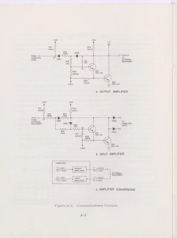
An output amplifier circuit (L--- card) in the computer converts the low-level internal logic voltages to high-level voltages riecessary for transmission by cable to external equipment. An input amplifier circuit (M___ card) converts the high-level cable volt-ages to the low-level internal logic voltvolt-ages. Although each circuit produces a 180 0 phase shift, it does not function as a logical inverter. A logical "1" (-3. 0v) input to an L__ card produces a 111 output (-0. 5). A UjI? input (-0.5) to an M--- card produces
a logical Ii!! output (-3. 0v).
OUTPUT AMPLIFIER
A schematic diagram of the output amplifier is shown in figure A-1, part a. Resistor ROl and the -20v supply hold the input to the circuit (point a) at binary 1 (-3v) when no input signal is applied to the circuit or when no data or control line is tied to the circuit. The collectors of transistors QOl and Q02 are connected to the base of QOl through 150 /#Lf capacitor COl which integrates the collector signal. Assuming that a binary 1" is supplied to the circuit, QOl and Q02 turn on placing a bw impedance between ground and the output line. The output of the circuit is effectively held to -0. 5v. Capacitor COl tends to oppose the initial conduction of QOl and Q02 by feeding back a less negative signal than was initially placed on the base. When COl approaches full charge, QOl and Q02 approach full conduction and the output rises to -0. 5v. Full saturation is prevented by feedback diode CR02. If a binary troll (-0. 5v) is applied to the circuit, the voltage divider action of the circuit causes QOl and Q02 to turn off. No feedback is applied to prevent cutoff so the output voltage rises toward -20v; the actual voltage is determined by the driven output circuit.
The binary 1 state of the output amplifier circuit is -0.5v (±0. 25v)* at the terminals of external equipments or computer under all conditions.
The binary "0" state of the output amplifier is -16v (±2.5v) at the terminals of the external equipments under all conditions.
In the binary "1" or '0" state an output amplifier circuit (whether located in the com-puter or in an external equipment) need supply no more than 10 ma to any single input amplifier circuit in another equipment.
FROM U-COMPUTER LOGIC
—20V —20\
6800 2200 ROl
R03 CR02
R02 0:0 R05 1b 150 CR01 220 22000 R04 2 + 20V 000
T. P, OUTPUT TO EXTERNAL EQUIPMENT 001 CDC (02
TL
002
COC 1030. OUTPUT AMPLIFIER
—20V —20V
ROl R04 2200 22:0
R02 R03 6800 (200
INPUT
P1
o
FROMEXTERNAL CR01 CR02 TO EQUIPMENT CR04 COMPUTER
ROS LOGIC 220
(b)
R06 CR03 1000 RO? 001
COC 102 22000 805
6800
002 COC 103 +20V -
INPUT AMPLIFIER
COMPUTER
ll
1 (-3V) j OUTPUT ( - 05 0( - 05V) AMPLIFIER 0 (—(6V)
EXTERNAL EQU 1 PMENT (-3V) INPUT "1 (-0.
0(-05V) AMPLIFIER 1 0 (-16V)
[image:25.642.34.631.15.819.2]AMPLIFIER CONVERSIONS
The output amplifier circuit can drive a maximum of five input amplifier circuits (50 ma maximum available current from output amplifier circuit).
Waveform characteristics of the signal from the output amplifier: No transition with siope greater than 8v per psec for a 30 foot cable Minimum transition time 2 Msec
Maximum transition time 4 psec
The circuit is capable of driving a total wiring capacity which can vary between 0 and 2000 ppf.
INPUT AMPLIFIER
[image:26.642.20.619.27.781.2]A schem.atic diagram of the input amplifier circuit used in the computer is given in figure A-1, part b. Resistor ROl and the -20v supply hold the input to the circuit (point a) at binary "0 (-16v) when no input signal is supplied to the circuit or when no data or control line is connected to the circuit. Assuming a binary "1" (-0. 5v) input to the circuit, the base of QOl (point b) rises positive due to the voltage divider action of R02, R06, R07, and R08. The collectors of QOl and Q02 then move in a negative direction. A feedback network including R03 and CR01 limits the negative potential of the collectors so that a binary 1 (-3v) is presented to the computer logic circuits. Conversely, if a binary tOT! (-16v) input is applied to the circuit, the
voltage divider action causes the transistors to increase conduction. The feedback network of R08 and CR04 limits conduction so that the output to the computer logic circuits approaches -0. 5v or binary 0".
The maximum steady-state current drawn from a line by an input circuit does not exceed 10 ma. The circuit is designed so that if the input wire is disconnected the effect will be as though a binary "0' were present at the input.
APPENDIX B BUFFER CONTROL
After a buffer operation is initiated by the main program, the actual word-at-a-time transfer of data is regulated by buffer control.
The heart of buffer control is the auxiliary scanner which ensures that no one buffer channel can monopolize the I/O section. The scanner probes the six buffer channels in search of action requests. The order in which the channels are scanned is 1-3-2-6-4-5. When an action request is detected, the scanner stops and initiates a buffer operation. After one word is transferred, the scanner probes all other channels before returning to transfer the second word. Up to six buffer channels may be active at the same time, each taking its turn at transferring a word.
[image:27.642.4.627.23.818.2]Although program Operations may continue while buffer operations take place, program and I/O operations must timeshare storage. Buffer Operations have priority.
Table B- 1 shows maximum word rates for any number of buffer channels in use at one time. These are maximum possible word rates; the actual word rates are determined by speed of exterrial equipment. The N orst condition' rate for one channel active
assumes that the main program makes a storage reference between each word buffered. No worst condition times are listed for more than one channel active since it is possible for two or more buffer channels to monopolize storage time.
The speed of most I/O equipment is lower than those shown in table B- 1 and actual speed of buffer operations is governed by the external equipment. Therefore, except when magnetic tape units are used, there is little conflict for storage time.
TABLE B-l. MAXIMUM WORD RATES Number of
Channels Active
Best
Conditions Conditions Worst
1 116KC 68.5KC
2 67.5KC
3 45KG
4 33.8KC
5 2,7KC
6 22.5KG