5
X
October 2017
Fuzzy Logic Controller Based Direct Torque
Control of PMBLDC Motor
Madasamy P1, Ramadas K2, Nagapriya S3 1, 2, 3
Department of Electrical and Electronics Engineering, Alagappa Chettiar College of Engineering and Technology, Karaikudi
Abstract: Direct Torque Control of the sensor less permanent magnet brushless DC motor with fuzzy logic speed controller is presented in this paper. The direct torque control is one of the vector based control in variable frequency drive control. This project proposes the control of torque directly and stator flux amplitude indirectly by using direct axis current. The torque error, flux error and estimated position of the stator flux linkage vector are used to change the switching sequence of the inverter through space vector pulse width modulation to control the motor speed. An impedance source network is coupled between the inverter and the DC supply to reduce the ripples in torque by boosting the inverter’s input voltage. The three phase voltage and current are converted to d- q axis to calculate the stator flux linkage vector, rotor angle and actual torque using park transformation. A fuzzy logic controller is used to generate a reference torque value by processing the speed errors. A prototype model is made for 24 V BLDC motor and the closed loop operation is obtained using fuzzy logic controller.
Keywords: Direct torque control, space vector pulse width modulation, park transformation, impedance source network, variable
frequency drive.
I. INTRODUCTION
A drive is an electronic device that harnesses and controls the electrical energy sent to the motor. The drive feeds electricity into the motor in varying amounts and at varying frequencies, thereby indirectly controlling the motor’s speed and torque. The speed of rotation of an electrical machine can be controlled precisely by implementing the concept of drive. The main advantage of this concept is, the motion control is easily optimized with the help of drive. In very simple words, the systems which control the motion of the electrical machines are known as electrical drives. This drive system is widely used in large number of industrial and domestic applications like factories, transportation systems, textile mills, fans, pumps, motors, robots etc. Drives are employed as prime movers for diesel or petrol engines, gas or steam turbines, hydraulic motors and electric motors. In this thesis the drive system is used to control the speed of the brushless DC motor.
Brushless motors fulfill many functions originally performed by brushed DC motors, but cost and control complexity prevents brushless motors from replacing brushed motors completely in the lowest-cost areas. Nevertheless, brushless motors have come to dominate many applications, particularly devices such as computer hard drives and CD/DVD players. Small cooling fans in electronic equipment are powered exclusively by brushless motors. They can be found in cordless power tools where the increased efficiency of the motor leads to longer periods of use before the battery needs to be charged. Low speed, low power brushless motors are used in direct-drive turntables for gramophone records.
In PMBLDCM, the dc field winding of the rotor is replaced by a permanent magnet to produce the air-gap magnetic flux. Having the magnets on the rotor, electrical losses due to field winding of the machine get reduced and the lack of the field losses improves the thermal characteristics of the PM machines and its efficiency. Absence of mechanical components like brushes and slip rings makes the motor lighter, high power to weight ratio for which a higher efficiency and reliability is achieved.
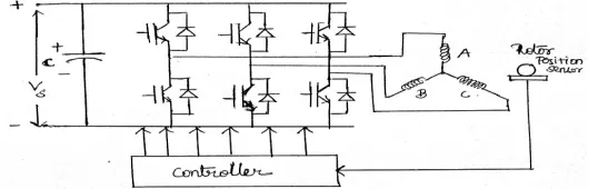
Basically it is an electronic motor and requires a three-phase inverter in the front end as shown in Fig. 1. In self control mode the inverter acts like an electronic commutator that receives the switching logical pulse from the absolute position sensors.
[image:2.612.173.442.635.720.2]The drive is also known as an electronic commutated motor.
Fig.2 Back EMF and current waveform (120 degree switching mode)
The six switches of the inverter T1 to T6 operate in such way so as to place the input dc current Id symmetrical for 120 at the
center of each phase voltage wave. The angle shown is the advance angle of current wave with respect to voltage wave in the case is zero. It can be seen that any instant, two switches are on, one in the upper group and anther is lower group. For example instant t1,
T1 and T6 are on when the supply voltage V dc creates back emf and current Id and both are placed across the line ab (phase A and
phase B in series) so that Id is positive in phase a. But negative in phase b then after 60 degree interval (middle of phase a) T6 is
turned off and T2 is turned on but T1 continues conduction of the full 120 degree angle. This switching commutates –Id from phase
b to phase c while phase a carry +Id the conduction pattern changes every 60 degree angle indication switching modes in full cycle.
The absolute position sensor dictates the switching or commutation of devices at the precise instants of wave. The inverter basically operating as a rotor position sensitive electronic commutator.In the previous mode the inverter switches were controlled to give commutator function only when the devices were sequentially ON, OFF 120 degree angle duration. In addition to the commutator function, it is possible to control the switches in PWM chopping mode for controlling voltage and current continuously at the machine terminal. There are essentially two chopping modes, current controlled operation of the inverter. There are essentially two chopping modes feedback mode and freewheeling mode. In both these modes devices are turned on and off on duty cycle basis to control the machine average current Iav and the machine average voltage Vav.Comprising with above mentioned many special
characteristics of BLDC is the present day researcher’s hotspot. It can be operated at improved power factor for which the overall system power factor is improved. BLDC drive could become an emerging competitor to the IM drive in servo like industrial applications. There is a great challenge to improve the performance with accurate speed tracking and smooth torque output minimizing its ripple during transient. Mechanical sensor setup is weak in construction and bulky. Also it is expensive which in turn increases the drive cost.
II. DIRECTTORQUECONTROL
The working principle for the basic DTC is to select a voltage vector based on the error between sensed and estimated values of torque and flux, rotor position estimation. DTC has the capability to work without any external measurement sensor for the rotors mechanical position. To satisfy the correct direction of rotation of a BLDC, the rotor position is required at the motor start up. DTC is simple because it does not require any kind of current regulators, rotating reference frame transformation or a PWM generator. The advantages of the DTC are to eliminate the d-q axis current controllers, associated transformation networks and the rotor position sensor. The disadvantages are low speed torque control difficulty, high torque and current ripple value, variable switching frequency, high noise level in low speed range.
Fig 3 BLDC Direct torque control system block diagram
Fuzzy logic is all about the relative importance of precision. Fuzzy logic has two different meanings .in a narrow senses, fuzzy logic is a logical system which is an extension of multi valued logic .but in wider sense fuzzy logic is synonymous with the theory of fuzzy sets. Several studies show, both in simulations and experimental results, that Fuzzy Logic control yields superior results with respect to those obtained by conventional control algorithms thus, in industrial electronics the FLC control has become an attractive solution in controlling the electrical motor drives with large parameter variations like machine tools and robots. However, the FL Controllers design and tuning process is often complex because several quantities, such as membership functions, control rules, input and output gains, etc must be adjusted. The design process of a FLC can be simplified if some of the mentioned quantities are obtained from the parameters of a given Proportional- Integral controller (PIC) for the same application. The design of conventional control system essential is normally based on the mathematical model of plant .if an accurate mathematical model is available with known parameters it can be analyzed., for example by bode plots or nyquist plot , and controller can be designed for specific performances .such procedure is time consuming. Fuzzy logic controller has adaptive characteristics. The adaptive characteristics can achieve robust performance to system with uncertainty parameters variation and load disturbances.
Fig.4 Z source network based DTC BLDC with PI controller MATLAB simulation
The PI controller has some drawbacks.1) It requires manual tuning parameter estimation for various speeds.2) the speed response using PI controller has a drop in the speed after the step time.These drawbacks can be overcome by using fuzzy logic speed controller. Since it provides the automatic speed control over a range and does not requires manual parameter estimation for various speed, it makes the overall control loop as the easy one.
[image:5.612.98.510.155.362.2][image:5.612.120.484.407.528.2]
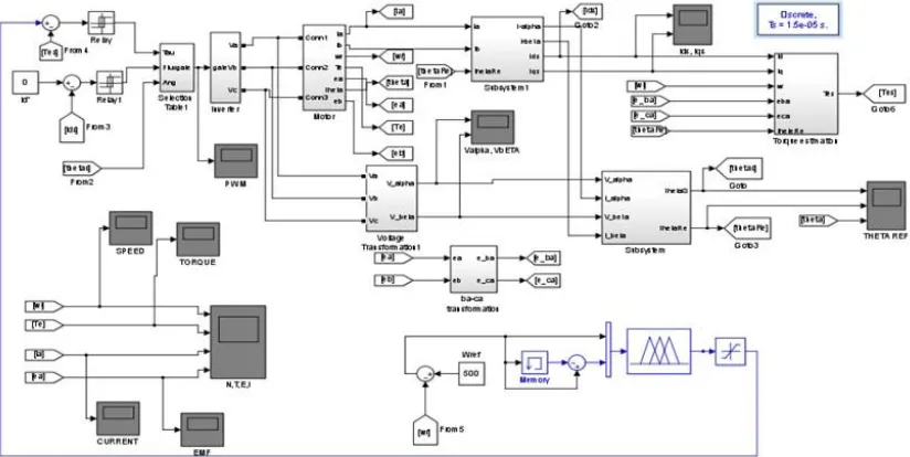
Fig. 5 Z source network based DTC BLDC with fuzzy logic controller MATLAB Simulation
Fig.7 Output DC voltage from the Z source network waveform
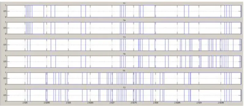
Fig. 8 PWM pulses to the Voltage source Inverter
Fig.10 BLDC Estimated rotor position angle waveform
[image:7.612.89.536.282.421.2]
Fig.11 BLDC Motor actual roor position angle waveform
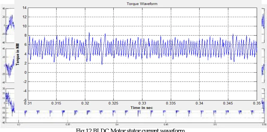
Fig.12 BLDC Motor stator current waveform
[image:7.612.89.535.456.677.2]Fig 14. BLDC Motor stator torque waveform with Z-source network
[image:8.612.100.528.325.505.2]It has been observed that the torque ripples are reduced in the circuit with Z-source network. The torque ripple value for the system without Z-source network is high. The Z- source network minimizes the ripples by boosting the supply voltage to the inverter. This ripple minimization reduces the unwanted noise and vibrations in the motor.
Fig.15 BLDC motor speed waveform using PI controller
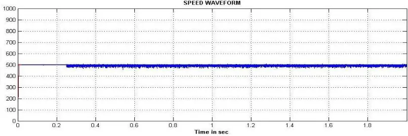
Fig. 16 BLDC Motor speed waveform using FLC controller
[image:8.612.99.512.533.671.2]rpm. It is observed from the graph the rise time of the PI controller is high. When the fuzzy logic controller is implemented for speed control, the speed is maintained constant after the step time, because it does not have any rise time. Hence the desired speed response is obtained through fuzzy logic controller.
III.PAGESTYLE
Fig.17 Block diagram of Hardware for Direct Torque control of BLDC Motor
Fig.18 Hardware implementation of FLC based DTC for BLDC motor
The 230 V AC voltage is stepped down to 24 V through a transformer and converted into DC by a rectifier. Then it is boosted up by an impedance network and fed to an inverter. The output of the inverter is supplied to the BLDC motor. The Back EMF of the motor is sensed to measure the actual speed and rotor position. An LC circuit is used to convert the trapezoidal Back EMF into sinusoidal waveform. Operational amplifier works as a zero crossing detector to convert the sinusoidal waveform into square waveform and given as the input to the controller. A current sensor is used to sense the current and fed to the controller. The Direct torque and indirect flux control is obtained by coding dumped in the controller. Closed loop operation is achieved by means of fuzzy logic controller. Initially no back EMF is developed in the motor so for a short duration the motor is operated in the variable frequency and variable voltage mode. Then it is operated in the proposed control method by changing the switch position. Separate power supply circuits are used for driver circuit and the controller.
Fig.19 Back EMF waveform of the BLDC motor
The proposed model is operated in the closed loop mode. The reference speed is set as 2508 RPM. The load is applied to oppose the rotation of the shaft to reduce the speed of the motor. The speed error is processed by the controller and finally the appropriate PWM pulses are generated to the inverter. So the actual speed is maintained nearer to the desired value.
IV.CONCLUSIONS
A prototype employing DTC of the sensorless PMBLDC motor is implemented in which the torque is controlled directly and stator flux amplitude is controlled indirectly through direct axis current. The closed loop operation is obtained by using fuzzy speed controller. The input voltage to the inverter is boosted by using an impedance network. The rotor position and speed of the motor are sensed by Back EMF sensing method. Since BLDC motors are used for many industrial applications due to their distinct advantages, this method reduces the cost of the drive for low power applications.
24 V
REFERENCES
[1] Afjei.E ,Anvari.B, A.Siadatan” Design and Simulation of Z-Source Inverter for Brushless DC Motor Drive” Specialty Journal of Electronic and Computer
Sciences 2015, Vol, 1 (1): 30-34.
[2] Bangcheng Han, Haitao Li and Jiancheng Fang,” Torque Ripple Reduction in BLDC Torque Motor With Nonideal Back EMF” IEEE Transactions on Power
Electronics, Vol. 27, No. 11, November 2012.
[3] Hamid A. Toliyat and Salih Baris Ozturk,” Direct Torque and Indirect Flux Control of Brushless DC Motor” IEEE/Asme Transactions on Mechatronics, Vol.
16, No. 2, April 2011
[4] Angelo Tani ,Domenico Casadei, Francesco Profumo and Giovanni Serra “FOC and DTC: Two Viable Schemes for Induction Motors Torque Control” IEEE
Transactions on Power Electronics, Vol. 17, No. 5, September 2002.
[5] David Howe , Yong Liu and Z. Q. Zhu,” Commutation-Torque-Ripple Minimization in Direct-Torque-Controlled PM Brushless DC Drives” IEEE
Transactions on Industry Applications, Vol. 43, No. 4, July/August 2007.
[6] Soumah Yaya and Wang Honghua” Research on reduction of commutation torque ripple in brushless dc motor drives based on fuzzy logic control” 2009
International Conference on Computational Intelligence and Security.
[7] Ick Choy ,Ji-Yoon Yoo , Joong-Ho Song, and Kyo-Beum Lee,”Torque Ripple Reduction in DTC of Induction Motor Driven by Three-Level Inverter With