A Realization Method of Protocol Conversion Between
Modbus and IEC61850
*
Fan Zhang1, Yongli Zhu1, Chunyu Yan2, Jiangang Bi2, Haijun Xiong1, Shuai Yuan2
1School of Control and Computer Engineering, North China Electric Power University, Baoding, China 2China Electric Power Research Institute, Beijing, China
Email: [email protected] Received 2013
ABSTRACT
In order to adapt to the construction needs of the smart grid, smart substation need to solve the problem of protocol conversion between the conventional non-standardized condition monitoring equipment and the standardized monitor-ing system. This paper proposed a realization method of conversion method between Modbus and IEC61850. Ob-ject-oriented technology is used for information model on Modbus. After the analysis of IEC61850 and MMS informa-tion and service model, to establish the model mapping relainforma-tionship between IEC61850, MMS and Modbus based on the principle of minimum information point which is one to one correspondence. Combined with the implementation of SISCO MMS-EASE LITE software development kit programming, giving a realization method using QT programming techniques based on the mapping model. Finally, the establishment the interval controller as an example of protocol scheme verifies the correctness and the feasibility of protocol conversion method.
Keywords: Modbus; IEC 61850; Protocol Conversion; Model Mapping; Consolidated Monitoring Unit
1. Introduction
With the gradual popularization and application of intel-ligent substation, IEC61850 standard is widely used in substation automation system [1]. State Grid Corporation developed the substation equipment online monitoring system technical guidance in the process of building a strong and smart grid by 2011 [2]. It defined that condi-tion monitoring system is structured into the process layer, the spacer layer and the station layer. The commu-nication between the layers is used IEC61850 protocol. To achieve the goal of intelligent substation, on the one hand to develop the standard specification condition monitoring equipment to replace aging seriously equipment, on the other hand, the condition monitoring equipment which need not replace should be completed the stan-dardized transformation to adapt to the current grid de-velopment needs. The conventional condition monitoring equipment mainly used in Modbus, IEC60870-5-103 (103), IEC60870-5-104(104), CAN bus standard as well as a large number of proprietary protocols nowadays [3,4]. Modbus whose structure is simple optimization and support a variety of characteristics of electrical interface and transmission medium is a protocol supported by most condition monitoring devices. Therefore, It is key
to study the protocol conversion between Modbus and IEC61850 for the substation condition monitoring equipment standardization.
Model mapping and protocol conversion research be-tween the IEC61850 standard and MMS, 103, 104 stan-dard has being focused on nowadays. The research on the model mapping between Modbus and IEC61850 standard is less [5]. [6] gives a model mapping method between Modbus and IEC61850 using the System Configuration Description Language schema file for expanded imple-mentation of the model, but does not give the specific engineering part of the protocol conversion module.[7] gives a CORBA-based the IEC61850 protocol conver-sion device. The method can be flexible and facilitate the realization of the protocol conversion, but due to the complexity of the CORBA ability, there are some limita-tions to realize it. IEC61850-8-1 has given the method to the implementation issues for IEC61850 which is to map the abstract information and services model to the Manufacturing Message Specification (MMS) [8]. Due to the complexity of the MMS, most of the current domestic manufacturers achieve the mapping of the communica-tion services by SISCO MMS-EASE LITE tool package in the development of IEC61850 substation product. [9,10] summarizes the information mapping correspon-dence between MMS and IEC61850 and gives the ser-vices mapping correspondence between ACSI and MMS *ProjectSupported by the science and technology projects of State Grid
service, but it cannot be used in the standardization of equipment condition monitoring access issues.
2. The Information Model and Mapping
2.1. The information model of IEC61850 and MMS
The actual communication functions and device has been described in an abstract way in IEC61850.It defines the five basic class model which include the Server, the logical device(LD),the logical node(LN),the data(Data), the data attribute(DA).A Server includes multiple LD, and each LD contains multiple LN, as well as each LN contains multiple Data. It can be seen that IEC61850 information model is a hierarchical and three-dimen-sional object-oriented structure.MMS is kind of specific communication service of IEC61850. The information Model of MMS is consistent with IEC61850. Each MMS application must contain at least one VMD object. VMD is the root in the object structure of the entire MMS, and other objects are included in the VMD object. Some types are included in the other sub-objects and become deeper sub-object.
In view of the MMS and IEC61850 model structure and its modeling method can carry out a similar analysis of the information structure of the Modbus protocol to complete the Modbus information modeling.
2.2. Modbus and its Information Model
GB/T 19582-2008 national standard gives two commu-nication protocols about the Modbus Application proto-col and service standards which included the Modbus serial link norms based on the TIA/EIA standard and the Modbus TCP/IP protocol based on the RFC793 and RFC791 standard [11,12]. And the Modbus serial link norms can divided into two communication modes of Modbus RTU and Modbus ASCII. Modbus RTU and Modbus TCP are mostly supported in substation condi-tion monitoring equipment with its simple optimizacondi-tion feature. The Modbus parameter type is less, mainly in-cludes coil, discrete, input registers and holding registers. The length of the first two is 1 bit, as the latter two is 2 bytes.
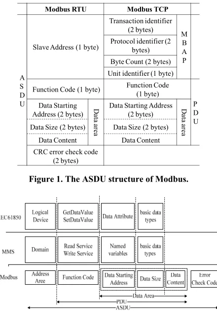
The Modbus data structure of the information is dif-ferent from the IEC61850 and MMS which is a linear plane. The information data is defined by a correspond-ing Application Service Data Unit(ASDU). Figure 1 shows the ASDU structure of two types of Modbus. In order to more clearly describe it contains information, we will divide the Protocol Data Unit(PDU) to three parts which contains the data starting address(DSA), data size(DS) and data content(DC). DBA and DS here refer to the read or write the starting address and the length of the parameter. The specific parameter type is determined
by the function code(FC). We can complete the informa-tion model of one ASDU by the object-oriented model-ing technology easily.
2.3. The Mapping Model between Modbus, MMS and IEC61850
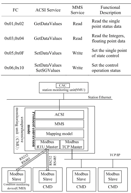
After the above analysis, the mapping from Modbus to MMS and IEC61850 is same to the flat-screen informa-tion points mapping to three-dimensional data objects. Figure 2 gives the mapping relationship between Mod-bus, MMS and IEC61850. The correspondence is sepa-rated by dotted lines. In the figure, the address field is the slave address of the Modbus RTU as well as the unit identifier of Modbus TCP.
The Information Mapping
Modbus address field is used to identify a condition monitoring device, so the Modbus address field is mapped to logical device of IEC61850 and the domain model of MMS.DSA can be uniquely identifies a device measuring point, so DSA is mapped to DA of IEC61850 and the simple named variables. DS is represented the number of the registers or coils and so on, therefore it will be mapped to the basic data types of IEC61850 and that of MMS.
Modbus RTU Modbus TCP
A S D U
Slave Address (1 byte)
Transaction identifier (2 bytes)
M B A P Protocol identifier (2
bytes) Byte Count (2 bytes) Unit identifier (1 byte)
Function Code (1 byte) Function Code(1 byte)
P D U Data Starting
Address (2 bytes) Data ar
ea
Data Starting Address (2 bytes) Data ar
ea
Data Size (2 bytes) Data Size (2 bytes)
Data Content Data Content
[image:2.595.313.533.393.709.2]CRC error check code (2 bytes)
Figure 1. The ASDU structure of Modbus.
The Service Mapping
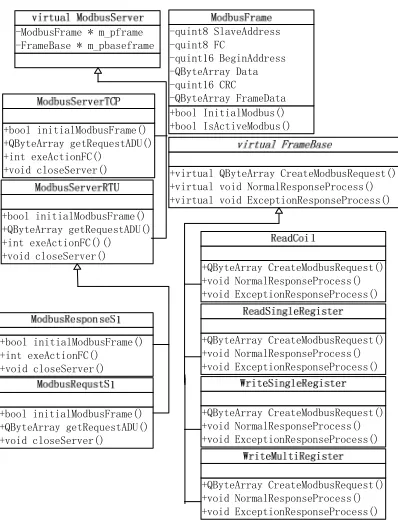
The function code specifies the different Modbus type of service, so it should be established the mapping from Modbus FC to the ACSI services or MMS services. The relationship is shown in Table 1.
3. The Realization of Protocol Conversion
System Based on the Mapping Model
3.1. Design of System Architecture
[image:3.595.55.285.383.722.2]We designed the following protocol conversion mode based on the mapping model. Firstly, the point data model of Modbus map to the variable of MMS, and then to finish the mapping from MMS to ACSI. Finally, to complete the Modbus protocol conversion to IEC61850. Figure 3 is a system architecture block diagram.The sub-station online monitoring system Technical Guidelines require the protocol conversion module should be deco-rated in comprehensive monitoring unit(CMU) to support multiple protocols translation of the state devices. In or-der to complete the following Modbus status monitoring device communication, we need to design the modbus master model in protocol conversion module.
Table 1. The mapping table of modbus function code.
FC ACSI Service Service MMS Description Functional
0x01,0x02 GetDataValues Read Read the single point status data
0x03,0x04 GetDataValues Read Read the Integers, floating point data
0x05,0x0F SetDataValues Write Set the single point of state control
[image:3.595.56.286.390.726.2]0x06,0x10 SetDataValues SetSGValues Write Set the control operation status
Figure 3. The system architecture block diagram.
3.2. Realization of System Software Design of the Software Architecture
QT as the software development tools is used in the system. Figure 4 is the design of software structure dia-gram. The system overall is design for three layers which include the top-level for MMS service layer, the mid-dle-level for protocol conversion layer and the low-level for Modbus service layer. The top-level provide MMS services to communicate with the station monitoring unit (SMU) or the standard client of IEC61850. If the service request which get from SMU is correct, it will send the request to the middle-level. The MMS requested service data in MMS-EASE LITE is encapsulated in the struc-ture MVLU_XX_VA_CTRL, if the service is read, XX is RD, otherwise XX is WR. The low-level receive or send Modbus messages as a Modbus Master to commu-nicate with the condition monitoring devices(CMD). The Modbus response data information from the correct re-sponse will be sent to the middle layer. The middle-level will complete the analysis of MMS service data informa-tion provided by upper and construct the corresponding Modbus request protocol frame to send to lower. And it will complete the analysis of Modbus response data from lower and construct the corresponding MMS response service to send to upper. The signals and slots mecha-nism of QT has good characteristics of inter-thread communication, so the information exchange of system between the three layers can utilize the mechanism to complete. Figure 6 shows the signals and slots function of the software design and identifies the relationships between the different signals and slots. The solid line represents the system receives signals and slots from the Modbus Response from CMD and the data flow. The broken line represents the association of the signals and slots after receipt of the MMS request and data flow.
Design of Modbus class diagram
Signal and Slot Function Signal/Slot Description mms_service_rd(MVLU_RD_VA_CTRL*)
SIGNAL
Top-layer mms_service_wr(MVLU_WR_VA_CTRL*)
on_response_rd(MVLU_RD_VA_CTRL*) SLOT on_response_wr(MVLU_WR_VA_CTRL*) onWriteDataReady (QByteArray)
SIGNAL
Middle-layer onRdResponse(MVLU_RD_VA_CTRL*)
onWrResponse(MVLU_WR_VA_CTRL*) onRequestRd(MVLU_RD_VA_CTRL*)
SLOT onRequestWr(MVLU_WR_VA_CTRL*)
onRecieveData (QByteArray)
device_data_ready (QByteArray) SIGNAL
Low-layer write_data_device (QByteArray) SLOT
Modbus Response
MMS Response
MMS Request
[image:3.595.311.535.533.719.2]Modbus Request
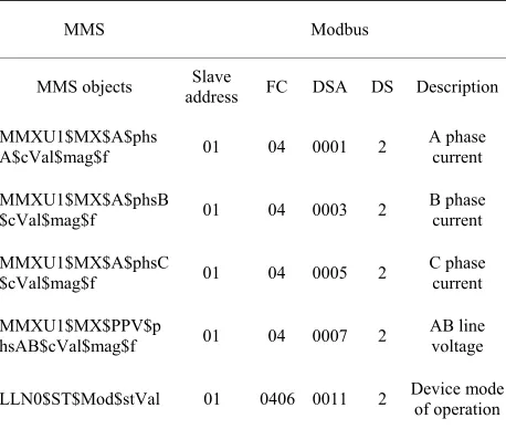
We complete the Modbus information modeling with the object-oriented approach. Figure 5 shows the Mod-bus class diagram design. The ModMod-busFrame class is used to describe the parameters of the Modbus ADU. Establishing ModbusServer abstract class as an abstract of the Modbus function can be inherited by different in-terface communication protocols for service. Modbus- ServerTCP and ModbusServerRTU inherited from Mod-busServer what achieve the service of Modbus TCP and Modbus RTU respectively. We established two subclasses for ModbusServerRTU. The two subclasses are respon-sible for building and parsing of the response or request of the Modbus RTU. In addition, we create an abstract class FrameBase. FrameBase can be inherited by differ-ent subclass which is decided by function code and can complete the building or parsing of different Modbus frame.
[image:4.595.329.520.86.551.2] The process of software
Figure 6 shows the flowchart of the system software. The system can be designed two threads, one thread is used for receiving the MMS requests from SMU or IEC61850 client, and another r is used for receiving the Modbus response from CMD. As a CMU should connect to multiple CMD, we provide a thread reincarnation scanning up to four serial ports or network ports in order to ensure the overall operating efficiency of the system. It is to say we should increase the number of threads to appropriate the number of devices. In addition, taking into account the MMS communication frequency of the upper and lower Modbus communication frequency in-consistency, we establish the policy of the pipe.
+bool InitialModbus() +bool IsActiveModbus() -quint8 SlaveAddress -quint8 FC -quint16 BeginAddress -QByteArray Data -quint16 CRC -QByteArray FrameData
+virtual QByteArray CreateModbusRequest() +virtual void NormalResponseProcess() +virtual void ExceptionResponseProcess()
+QByteArray CreateModbusRequest() +void NormalResponseProcess() +void ExceptionResponseProcess()
+QByteArray CreateModbusRequest() +void NormalResponseProcess() +void ExceptionResponseProcess()
+QByteArray CreateModbusRequest() +void NormalResponseProcess() +void ExceptionResponseProcess()
+QByteArray CreateModbusRequest() +void NormalResponseProcess() +void ExceptionResponseProcess() -ModbusFrame * m_pframe
-FrameBase * m_pbaseframe
+bool initialModbusFrame() +QByteArray getRequestADU() +int exeActionFC()() +void closeServer() +bool initialModbusFrame() +QByteArray getRequestADU() +int exeActionFC() +void closeServer()
+bool initialModbusFrame() +int exeActionFC() +void closeServer()
+bool initialModbusFrame() +QByteArray getRequestADU() +void closeServer()
Figure 5. Modbus class diagram.
Figure 6. The flow chart of software.
[image:4.595.72.271.459.719.2]tables as the mapping model. Table 2 shows the basic information mapping table for storage Modbus informa-tiong and MMS variable mapping relationship. Table 3 shows the writing services relationship and Table 4 shows the reading services relationship. The initialization of database is to resolve the mapping associated file which establish by manual.
Table 2. Basic information mapping table.
Field Type Description MMSVariable VarChar(65) MMS variable name
SlaveAddress Int Modbus address area StartAddress Int Modbus data starting address
DataSize Int Modbus data size
Table 3. The service relationship of read.
Field Type Description MMSVariable VarChar(65) MMS variable name
[image:5.595.57.289.422.500.2]FunctionCode Int Modbus Function Code (0x01~0x04)
Table 4. The service relationship of write.
Field Type Description
MMSVariable Varchar(65) MMS variable name
[image:5.595.57.286.539.733.2]FunctionCode Int Modbus Function Code (0x05,0x06,0x0F,0x10)
Table 5. A part of the data object of interval controller mapping relationship.
MMS Modbus
MMS objects address Slave FC DSA DS Description MMXU1$MX$A$phs
A$cVal$mag$f 01 04 0001 2 A phase
current MMXU1$MX$A$phsB
$cVal$mag$f 01 04 0003 2 B phase
current MMXU1$MX$A$phsC
$cVal$mag$f 01 04 0005 2 C phase
current MMXU1$MX$PPV$p
hsAB$cVal$mag$f 01 04 0007 2 AB line voltage
LLN0$ST$Mod$stVal 01 0406 0011 2 Device mode of operation
4. Case Study
MMS-EASE LITE gives the corresponding IED con-figuration file of the interval controller E1Q1SB1. We will complete the mapping model of E1Q1SB1 by the protocol conversion method. First, MMS objects should be created according to the IED file to complete the mapping from MMS to IEC61850 standard. Then the mapping model should be established from MMS objects to Modbus information model after the analysis of MMS objects. In the example, we test a part of data objects and properties of logical Node MMXU1 and LLN0. The Ta-ble 5 shows the testing objects. Finally, we will read or write the phase current, line voltage and so on from the analog interval controller by the IEC61850 standard cli-ent.
By simulation, we can convert the ACSI or MMS ser-vice request to corresponding Modbus request correctly and return the corresponding Modbus request by the analog sub-station of Modbus. The system can parse the information data integrally and return the response of ACSI or MMS correctly. In addition, the pipeline strat-egy makes the condition monitoring equipment and sta-tion-side monitoring device to achieve asynchronous communication and solves the inconsistent problem of the communication frequency between MMS and Mod-bus. The process and results of the test results show that the system is stable and reliable.
5. Conclusions
The paper researches the information of MMS, IEC61850 and Modbus and their mapping relationship between their models firstly. The model can accurately describe the point information and can be more easily achieved with MMS and IEC61850 mapping. According to the Modbus information model, a protocol conversion method is given by QT technology and MMS-EASE LITE tools package then. The program not only facili-tates the realization of the protocol conversion, but also provides a guideline to the private protocol which has a linear plane features mapping with IEC61850. Finally, Interval controller as an example verifies the feasibility and correctness of the established mapping model and protocol conversion program. The testing results are sat-isfactory.
REFERENCES
[1] S. Li, Z. L. Jia and Z. H. Ying, “Reconstruction of Non-integrated Automation Substation Based on IEC61850,” Electric Power Automation Equipment, Vol. 30, No. 5, 2010, pp. 139-141.
[3] D. W. Wang, Y. L. Zhu and Y. Wang, “Condition Moni-toring and Integrating Platform for Power Transmission and Transformation Equipment Based on IEC61850,” Automation of Electric Power Systems , Vol. 34, No. 13, 2010, pp. 43-48.
[4] D. W. Wang, Y. Wang and J. Di, “Design Scheme of Condition Monitoring System for Smart Substation,” Automation of Electric Power Systems, Vol. 35, No. 18, 2011, pp. 51-56.
[5] J. Zhang and S. Z. Hou, “Research on IEC 61850 Sever Application Based on MMSEASE Lite,” Telecommunica-tions for Electric Power System, Vol. 32, No, 227, 2011, pp. 55-58.
[6] D. W. Wang, C. Y. Yan and J. G. Bi, “An Approach to Mapping Between Modbus and IEC61850 for Condition Monitoring Communication Gateway in Substations,” Automation of Electric Power Systems, Vol. 36, No. 19, 2010, pp. 78-84.
[7] W. L. Wang, G. H. Xu and Z. H. Zhu, “Research of Pro-tocol Gateway Device Based on CORBA Technology,” Power System Protection and Control, Vol. 37, No. 7,
2009, pp. 63-66.
[8] IEC61850-8-1 Communication networks and systems in substations, Part 8-1:Specific communication service mapping(SCSM)—Mappings to MMS(ISO9606-1 and ISO9506-2) and to ISO/IEC8802-3[S].2004.
[9] K. Dong, B. Guan and W. Wang, “Research on Mapping between IEC61850 and MMS,” Power System Protection and Control, Vol. 38, No. 10, 2010, pp. 92-95.
[10] S. J. Wang, S. R. Ye and L. Zhang, “Analysis of Imple-menting the IEC61850 Model with MMS-EASE Lite,” Instrumentation Technology, No. 6, 2009, pp. 50-53. [11] GB/T19582.1-2008 National Standard of the People's
Republic of China “The Industrial Automation Network Specification Based on Modbus Part 1: Modbus Applica-tion Protocol,” 2008.