ASSOCIATION
European Atomic Energy Community - EURATOM/
Brown Boveri / Krupp Reaktorbau GmbH, Diisseldorf/
Kernforschungsanlage Jiilich des Landes Nordrhein-Westfalen - e.V.
THTR
STATUS REPORT
1965
1966
THTR 4
This document was prepared under the sponsorship of the Commission of the European Atomic Energy Community (EURATOM).
Neither the EURATOM Commission, its contractors nor any person acting on their behalf :
Make any warranty or representation, express or implied, with respect to the accuracy, completeness, or usefulness of the information con-tained in this document, or that the use of any information, apparatus, method, or process disclosed in this document may not infringe privately owned rights; or
Assume any liability with respect to the use of, or for damages resulting from the use of any information, apparatus, method or process disclosed in this document.
This report is on sale at the addresse!' '
I
at the price of FF 16,50When which i
FB
ASSOCIATION
European Atomic Energy Community - EURATOM/ Brown Boveri / Krupp Reaktorbau GmbH, Diisseldorf/
Kernforschungsanlage Jiilich des Landes Nordrhein-Westfalen - e.V.
THTR
STATUS REPORT
1965
1966
THTR 4
The Kernforschungsanlage Jtilich des Landes Nordrhein-Westfalen
(KFA), Euratom and Brown Boveri/Krupp Reaktorbau (BBK) have
entered into an Association agreement in May
1964
wi\h theobjective of developing the pebble-bed high-temperature
gas-cooled reactor concept.
The THTR Association has organized on December
16, 1965,
itsfirst public meeting called "Status Report", where the advance of the laboratory work performed and of the engineering study
1. P. Caprioglio:
Introduction by the President of the Steering Committee 1
2. R. Schulten
Introduction by the Project Leader
3.
C.B. von der DeekenThe Experimental Work Performed for the Development of the THTR Project
4.
F. ScholzExperimental Studies on the THTR Heat Exchangers
5.
H.J. StockerConsiderations on the Design of Fuel Elements and Structural Graphite
6.
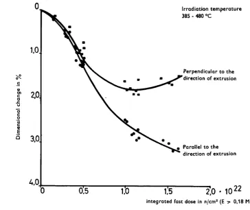
B. LiebmannThe Fabrication of Fuel Elements
7.
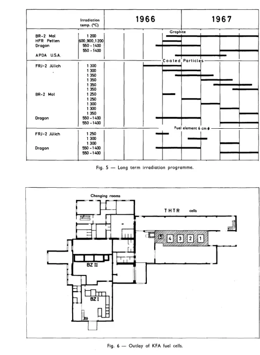
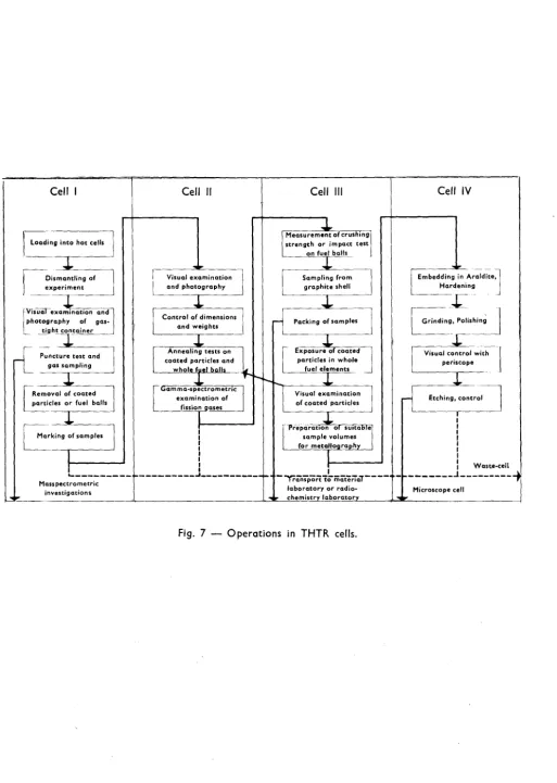
P. Jelinek-Fink and L. ValetteThe Irradiation Programme
8.
A. SchatzNeutron Physics Investigations
9.
H.W. MlillerStatus of the Development of the 300 MW Prototype
10. H. Schafstall
Main Characteristics of the 300 MWe Plant
11. U. Hennings
Some Special Engineering Problems
12. W. Rausch
The Fuel Element Cycle
7
21
33
41
47
57
71
93
105
Introduction by the President of the Steering Committee
Dr. P. Caprioglio
l) The Kernforschungsanlage Julich des Landes Nordrhein-Westfalen (KFA), EURATOM and BROWN BOVERI/KRUPP Reak-torbau (BBK) have entered into an Association
agree-ment in May
1964
with the objective of developing thepebble-bed high temperature gas-cooled reactor concept.
A Steering Committee fixes the yearly program and the budget of the Association contract and directs its
execution.
It is composed of six members
two designated by KFA
one designated by BBK
including one representati-ve of the Federal Ministry
for Scientific Research (Bundesministerium fur
Wissenschaftliche Forschung) who supports part of the KFA
financial burden
three designated by EURATOM
The project leader, Dr. R. Schulten, is the Chief Executive
and is responsible with a small staff (Projektleitung) of
the coordination and execution of the work by the
As you will see during today' presentation, the
programme of the
THTR
Association bears a veryclose similarity in many fields with the Dragon
Project, as well as with the
HTGR
programme inthe USA. This is why it was felt useful to
have cooperation agreements with both of them.
These agreements have allowed between other
things, the possibility of making use of the
Dragon Reactor, which is successfully being
operated at 10 MW. Furthermore, this allows a
very fruitful cooperation with the USAEC in the
field of fuel elements.
2) All reactors under development will have chances
of success only as far as they can beat both
pre-sent type of reactors and the conventional power
station on economic grounds.
The conventional power .station to beat - as
operational in the 70's - will have a capital
cost of around 120 $ kW - i.e. 480 DM/kW - and a
fuel cost of around 3.5 mills/kWh i.e. 1.2
-1.4 Pf/kWh -. If one could do better for both
items, one would make nuclear energy competitive
not only for base load operation but also for
annual utilizations as low as 3000 hrs.
All reactor types under exploitation today for
electricity production are capable of better
performance as far as the fuel cycle.cost is
concerned. In fact, they all show a fuel cycle
cost of less than 2 mills/kWh. In this respect
they are therefore already very good. The reason
why nuclear energy is not yet competitive, or, if
base load operation, very large sizes of stations
-is because the capital cost of present reactor types
is too high.
These figures show that, if the aim of improving the
fuel cycle is always a worthy one, it is not the
essential one, even when increased uranium ore costs
are considered. The real and difficult problem is
to improve on the capital cost; here is where large
savings have to be made and can be made.
The capital cost of a reactor plant is determined
more than by any other single item by the moderator
and the coolant, that are chosen. The coolants
which have been used for the present generation of
near-competitive power stations are light water and
co
2 ~as. Let's first see which are the possibilities
of further development of present established reactor
systems:
Light Water Reactor
Although the reactor as such is a rather cheap piece
of equipment, the implications of an essentially poor
thermodynamic steam cycle on the attached
convention-al equipment (turbines, steam ducting, etc.) heavily
outbalances the system towards relatively high capital
costs. The need for better steam cycles comes not so
much from the desirability of higher efficiencies, but
rather from the need of cheaper components. Nuclear
superheating is therefore looked at as the natural
follow-up. It is enough here to mention that a
super-heated steam is, from the heat transfer point of view,
so much more similar to a gas than to water, to
under-stand that the attractive simplicity and compactness
of a PWR or BWR will be impaired by the adoption of
superheating. After all this is a consequence of
changing coolant and adopting a corrosive and poor heat
Gas Graphite Reactor
The latest version of it, the AGR looks still
rather expensive as far as capital cost is
con-cerned. The main achievement is indeed to have
acquired a "conventional" steam cycle. The next
step is obviously to improve the reactor and heat
exchanger portion and this can best be done by
adoption of a better heat transfer coolant,
allow-ing higher power densities.
This leads us quite naturally to the High
Tempera-ture Gas Cooled Reactor:
The HTGR is one of the most proven amongst the
advanced reactor concepts. Not only three
experi-ments are being built in the world (Dragon, AVR and
Peach Bottom), but also one of them, Dragon, has now
been operating with full satisfaction for some while
at rather high power level. The Helium cooling
tech-nology can be considered as acquired, since most
pro-blems connected with it (leak tightness and coolant
purities, for instance) have found a satisfactory
solution. The problems connected with the new fuel
concept involving coated particles in a graphite matrix
have also been overcome and another clear year of
satis-factory performance of Dragon will increase our
confi-dence. The advantages connected with the He cooling
technology, leading to a very compact and cheap reactor
design, should enable the HTGR to compete with light
water reactors en capital cost.
The all-ceramic fission product retaining fuel concept,
together with the excellent neutron economy in
conjunc-tion with the use of the Thorium cycle should make the
fuel cycle of this particular reactor one of the cheap-est, not only today, but also tomorrow when increased
uranium costs will have to be considered. It should
be pointed out that it is only for U-ore costs as high
as 40 $/lb
u
working as a converter would begin to jeopardize
the economics of the system. This gives us
rea-sonable assurance that, should the HTGR prove to
be competitive today, it would remain so for a
very long time to come. It is our conviction
that if fast breeders were present at long term,
their use could best be restricted to base load
duty. Good converters, such as the HTGR, would
profitably take care of the lower load factors
,
without solution of continuity.
The HTGR as it stands today is already a rather
advanced concept, and yet has a tremendous
poten-tial for further development towards reduction of
both capital and fuel cycle cost, should this
prove necessary. Further capital cost reduction
can be achieved by adoption of a direct gas
tur-bine cycle. This would eliminate He to steam
heat exchangers and would give place to a more
compact rotating machinery. This last statement
should not surprise too much when one considers
that a noble gas such as Helium in the range of
temperatures achievable in an HTGR (up to 900°C)
and in the range of pressures that we already
envisage today(up to 40 to 50 atm) can carry a
tremendous amount of energy per unit volume and
can, therefore, give place to high power compact
machinery.
As far as the fuel cycle is concerned,
develop-ment in fuel reprocessing technology and adoption
of Beryllium oxide in the reactor core should
achieve conversion factors sensibly above unity,
which means breeding. It is, however, important
to note that although the possibility of
achiev-ing very high ccnversion factors exists, this
does not mean that we have to take immediate
One of the things that, to our minds, makes the
HTGR so attractive, is the extreme flexibility
of its fuel cycle. Conversion factors can always
be optimized according to the actual cost of
fissi-le material, so that the state of development of
reprocessing and refabrication technology can allow
any fuel cycle to be chosen from once through cycle
to breeding.
In a year or so, time will be ripe for a decision
upon the construction of a prototype. After all,
that is just what is going to be done on the other
side of the Atlantic, where an electricity producer
has already decided to buy a 330 MWel prototype.
A turnkey contract has recently been signed between
Public Services of Colorado and General Atomics for
a capital cost of 139 $/kWel
(556
DM/kW) installed,a guaranteed :fuel cycle cost of
1.6
mills/kWh(0.64 Pfg./kWh) over the first
8
years of operation.USAEC will contribute with about 40 million dollars
including research and deveiopment as well as a
con-tribution for "first of kind" components. Keeping
into account that this is the first big step towards
gas cooling technology in the USA, one can conclude
that the Colorado plant is going to be one of the
Introduction by the Project Leader
Profo Dr. R. Schulten
This is the first time that we have reported on the THTR project
to a large audience. After the contract covering this
associa-tion had been signed in May last year, a steadily increasing
number of staff members worked on this project in an attempt
to have the development work and the construction documents
for a THTR prototype plant ready by the end of
1967.
About 220persons are at present working on this project. Within the next
two years, a staff of about 300 members will be availableo
The high-temperature reactor is a continuation and a further
development of the gas-cooled graphite reactor type. It is a
wellknown fact that this reactor type- above all the Magnox
reactors built in Britain - today accounts for the bulk of
nuclear power production and that at present the greatest
ope-rating experience has been obtained with this type of reactoro
It is therefore an encouraging confirmation of our development
work to see that the AGR,, as a continuation of the Magnox
gra-phite reactor, shows a clear trend towards the
high-tempera-ture reactor. Many components of the AGR are also used by us,
such as the prestressed concrete vessel with heat insulation,
the blowers, the graphite blocks, the heat exchangers and
typi-cal measuring and regulating gear. However? new features are
the use of helium instead of
co
2 and graphite coated particles
instead of
uo
instead of slightly enriched uranium is an additional
inno-vation.
The following considerations show the real advantages to be
gained from the further development of the AGR to a
high-temperature reactor:
In comparision with the AGR, the initial temperature of the
high-temperature reactor is increased from 670° C to more than
750°
c.
This temperature increase, in conjunction with theuse of helium instead of
co
2, enables the power of the AGR to
be increased by more than 100
%.
This gives a decisivereduc-tion in the capital cost of the plant. The utilizareduc-tion of
coa-ted particles permits higher burn-ups of more than 100,000
.
MWd/t, as the results of our irradiation experiments indicate.
Higher burn-ups mean lower fuel processing costs. Finally, the
use of the thorium uranium fuel cycle.results in a major
tion in the fissionable material consumption and thus a
reduc-tion in fuel costs. Another characteristic of the thorium cycle
is the fact that a comparatively low fuel input isrequired, the
advantage of which is confirmed by the reduction in capital fuel
costs.
Figs. 1 and 2 show the 300 MW prototype, construction of which
is planned under the German atomic programmeo The gas flow for
the transfer of the heat from the reactor is from top to
bot-tom; the gas is collected underneath the core and passed to
the steam generators at the side, where it is cooled and then
transferred through the blowers along the reactor shell back
to the upper parL of the reactor.
In contrast to high-temperature reactors developed e~sewhere,
loading and reloading of the reactor core can be carried out
continuously during operation of the THTR. Our development work
Fig. 1 - Sectional view of the 300 MWe THTR prototype.
[image:15.701.53.562.70.782.2] [image:15.701.55.510.88.401.2]AVR
15 MWe
,y-l /~
1i I i I
Prototype 300 MWe
Study 1 OOO MWe
0 10 20m
[image:16.701.137.661.78.613.2]reloading of the reactor are favorable for the operation and
for the fuel cycle, since the capital costs can thus be
redu-ced appreciably.
As the fuel loading, the flow of the fuel elements through the
reactor and many important parts of the loading plant are
simi-lar to the AVR reactor. The removable blowers are mounted
late-rallyo The steam generators can be replaced if necessary. It is
assumed that this facility can subsequently be dispensed with.
This will permit the size of the concrete vessel to be reduced
considerably. The plant is of the so-called integral design,
i.e. all the parts of the primary circuit, including the steam
generators are located in the same pressure vessel. The nuclear
part of the power plant consists essentially of the reactor,
the gas purification plant and the helium tanks. Auxiliary
equipment e.g., for the removal of the steam generators, are
housed in the same buildingo
Fig. 3 shows the advantages of the prestressed concrete vessel.
The volume of the 300 MW plant is not much greater than that
of the AVR reactor and the 1000 MW plant is only slightly bigger
than the 300 MW plant. The relative volume profit obtained from
the transition from 300 to 1000 MW is based on the fact that
the steam generators for a 1000 MW plant need not be exchangeable.
A comprehensive experimental programme is an essential
prerequi-site of the construction of these nuclear power plants. In the
past, Brown Boveri/Krupp has already carried out important expe-rimental work, and the work performed under the THTR association
was in continuation of this. It is not possible to deal with
all these experiments in detail in our reports today, for which
reference should be made to our annual reports. Broadly speaking,
the experiments covered the following fields:
1) research on graphite: physical, chemical and mechanicar
2) the investigation of heat transfer and helium flow;
3) the study of mass transport and gas purification
problems;
4)
the behaviour of fission products: diffusion anddeposi-tion in the circuit;
5) the verification of reactor components, e.g., valves
and fittings, drive mechanisms and penetrations;
6)
the development of methods for testing gas-tightness;7) studies on dry bearings in high-purity helium.
I should like to mention certain experiments which are
characte-ristic of our THTR reactor, namely:
8) the behaviour of the pebbles as they flow through the
reactor core;
9)
the determination of the burn-up condition of the fuelelements;
10)
the development of an economical gas purification systemon a chemical basis.
For the development of the fuel elements numerous studies were
also carried out under our contract of Association. Spherical
fuel elements with fuel in the form of coated particles are
used in the THTR. These particles are expected to give a maxi-o
mum operating temperature of 1250 C and a burn-up of 100,000
MWd/t. The particles are either randomly packed in hollow spaces
or embedded in a graphite matrix. At present, the Association
has set up a production capacity of up to
8
kg/d through asub-contractor, which could meet up to 25
%
of the currentrequire-ments of a 300 MW power plant. These studies and the testing
of the fuel elements and particles under the irradiation program
will be discussed in greater detail this morning.
The development work on a new reactor.type are only justified,
when
genuine
eoonomic
advantages can be expected.
Figo4
shows
•
the calculations of the capital costs of high-temperature reactors. They indicate that for high-temperature reactors in
the region of 600-1000 MWe the capital costs will be from
600 to 500 DM/kw.
The following points are to be made in connection with Fig.
4:
l) With regard to the Colerado power plant, mention should
be made of the fact that, in addition to the capital costs
given here, another 40 million dollars is being paid by
the AEC for development work, fuel loading and one-time purchases.
2) Although a precise cost break.down cannot be given until
after completion of our design work, it is possible to state even now that the high-temperature reactor offers a good development potentialo
a) Owing to the use of prestressed concrete, one part of the reactor is cheap to build;
D) Because of the excellent thermal properties of helium, the steam generators have a high heat flux;
o) On account of the steam conditions which can be achieved,
the turboset and the other parts of the conventional
equipment are cheap, while in larger nuclear power plants
these account for the majority of the construction cost.
It is well known that the majority of power plants can only be
operated with load factors of less than 60
%,
in order to meetthe requirements of the electricity market. In this connection, the future possibilities of operating nuclear power plants with
low fuel costs but higher construction costs are overestimated
since the energy generating cost is in this case much more
depen-dent on the low load factor demanded by the market. For this reason our development work is aimed at reactors having load
fact in the cost calculations effected so far. In comparison with
other reactor types, the high-temperature reactor occupies a
favo-rable position in this respect, in particular because the capital
costs for construction and the fuel are considerably lower.
Fuel studies were also carried out by the Association and other
development groups, leading to the following results (Fig.
5):
In the figure the fuel costs are given as a function of the total
capacity of the reactors. Up to 10,000 MW no allowances were made
for reprocessing, but above this value reprocessing was assumed.
A fairly large number of high-temperature reactors with a total
capacity of 15,000 MW are shown to the right of the figure.
We have studied one group of problems which are frequently
over-looked when assessing fuel costs. For obvious reasons, a limited
number of reactors having a low output entail fairly high
fabri-cation and reprocessing costs. Only when the total capacity is
higher are these costs likely to fall. The fabrication costs
drop fairly fast when the power is stepped up. As technical
de-velopments stand at the present, on the other hand, reprocessing
costs are only low enough for large capacities if the units are
only used for one type of reactor, as is assumed here. This is
the particular economic problem involved in the introduction of
a new reactor type, and perhaps greater attention should be paid
to it in the future. Precise consideration of the matter shows,
for instance, that substantial difficulties arise when a new
reprocessing unit is required. The considerable cost involved can
then only be justified by the operation of several nuclear plants
of the same or a similar type at the same time, which presents
a problem in the case of new developments.
In the case of high-temperature reactor, this problem is to be
solved in two ways:
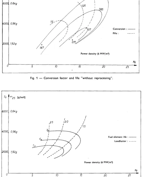
1) By using a fuel cycle without reprocessing as long as the
'OM/kW
3 0 0 0 ~ - r I o 7
-i-
_ _ L . _I I
1000
1 PEACH BOTTOM-GA 40 MW
2 Proj•kt BBK, THTR 1SOMW
3 ProjMt BBK, THTR JOOMW
, Proj•kt PBR-ORNL
330MW
5 COLORADo-GA
330MW 6 DRAGON
500MW
7 Proj•kt BBK, THTR
DM/kW 2812 1180 752 762 545 680
1000MW 500
8 Proj~kt GA
1039MW 500
~-===--o-o--_----'---78
0 ' ~ + ~ + ~ + ~ + ~ + ~
-0 200 400 600 800 1000 1200 MW
Fig. 4 - Specific capital costs of high temperature reactor stations as a function of the reactor power.
0.8
0.7
Dpf/kWh
0. 6 _ without reprocessing
0.5
o_,....__ __
0.3
with reprocessing
ond recycling q
0.2 - - - --- +
-0.1
0
0 1000 5000 10000 15000 MW
[image:21.701.127.466.74.421.2] [image:21.701.127.468.463.810.2]2.0
1.8
1.6 ~.
1.4 ~
1.2
1.0-0.8
0.6
-
0.4-02
0
Dpf/kWh
· ; - - ~
_
__:_:__....---~~""""'.4--- __:_:__....---~~""""'.4---1__:_:__....---~~""""'.4---__:_:__....---~~""""'.4---__:_:__....---~~""""'.4---__:_:__....---~~""""'.4---__:_:__....---~~""""'.4--- j ,~ - ..
I
Fuel-costs
_ , . . . 1
_ _ __.:..Rc..::uc..cnc.:.nlc:.:n,,_g---=cc.=.os=-:t:=..s _ _ _ _
Investment-costs
6 8
1965 1975?
16 1985?
$/lb
2) By adapting the fuel cycle to existing reprocessing units,
i.e., by developing a special head end in collaboration
with Eurochemic or the Thorex plant in Italy, for instance.
It can be seen that the two-type loading (so-called feed and
breed concept) which is planned by the Association and which
forms the basis of our calculations will give very favourable
fuel costs. The one element is here a so-called breeder element
containing thorium and fissile material in equilibrium
concen-tration; the other contains only fissile material and is used
to control the reactivity and power density.
The next figure shows the total costs for one kWh, the capital
costs and operating costs being taken from other publications
(Fig.
6).
The percentage o~ the costs which depends on the priceof uranium ore will therefore be less than
5%
of the total costper kWh. The operation of the high-temperature reactor thus seems to be largely independent of the ore price. A twofold increase
in the ore price which is possibly to be expected by the year
2000 will hence have no major effect on the cost and
consequent-ly the operation of such reactors. It may be stated here that
the capital costs have a much greater influence on the total
costs. Moreover, we feel that owing to the relatively low
capi-tal costs, as has already been said, high-temperature reactors
can also be operated in greater numbers in the future with
loa--..._
ding factors of less than 70
%.
The most important problems and their resulting studies for the
following two years will be as follows: the results hitherto of
the test programme and the experience acquired during the
cons-truction of the AVR can be utilized in the 300 MWe prototype
planto An important factor here is the large-scale
simplifica-tion which should be possible by virtue of the favourable results
obtained in connection with the low fission product release, the
The irradiation programme is concentrated on two specific fuel
element types and to definite graphites to be used for building
up the core. Furthermore, the burn-up measurement and the
trans-position of the chemical cleaning process for the helium
deve-loped by us are regarded as particularly urgent problems. All
the studies are based on the assumption that extrapolation of
the components from a 300 MWe plant to a 1000 MWe plant is
possible.
To sum up, perhaps the present status of the project can be
out-lined as follows:
1) The research carried out under our Association will during
the next two years be mainly devoted to the problem of
radiation damage and graphite corrosion at high neutron
doses and high temperatures. In this way it is hoped to
work out precise specifications for the most suitable types
of graphite for the reactor internals.
2) The gas purification and burn-up measurements techniques,
which have so far only been tested in laboratory experiments,
must be studied on a larger scale.
3)
The development work and the finalization of the data havereached the stage where the design and construction of the
300 MWe protetype can begin in
1966
and, parallel to it,the elaboration of a design study on a 600 MWe unit.
4)
Apart from the oxide particles, which is a special problemto be tackled next year, work on the fuel and fuel elements
has progressed so far that a start can be made on
large-scale production. The
1966/67
irradiation program willcon-centrate on the testing of these products. The production
process is largely automatic.
With regard to the future potential of the high-temperature
inci-the thorium fuel cycle:
1) The.high-temperature reactor is flexible with regard to
the choice of fuel. Both slightly-enriched uranium and
plutonium and also highly-enriched uranium with the
corres-pondingly adapted conversion factor can be used. Even on
the most pessimistic assumptions with respect to uranium
ore prices, the calculated fuel costs are only-slightly
,
in excess of those given for other reactors, which can most
likely be more than offset by cost reductions obtained by
breeding. These are to form the subject of studies next
year.,
2) No fissile-material-producing reactors of another type are
required to introduce this system.
3) With the construction and operation of the 300 MW
demons-tration plant, the development can be completed in
6-8
years.4)
Now that the fuel has been shown to have good retainingpro-perties with regard to fission products, there are
apparent-ly no longer any safety problems.
The high-temperature reactor offers an economic and competitive
solution to the power supply situation not only for the next few
decades, but also over the long termo
The further development to a breeder is mainly a question of the
size of the reactor and of the development of a suitable
repro-cessing method. Also, the use of BeO, which can be employed in
the reactor as a structural material in addition to graphite and
gives a better neutron balance, is a matter which does not imply
a modification in the reactor concept itself, but a further
In the course of the following talks we shall try to give you
as accurate as possible a picture of what has been achieved
so far and of the problems which still have to be solved. It
The Experimental Work Performed for the Development
of the THTR Project.
Dr. C.B. von der Deeken
Out of the vast research and experimental work carried out,
I would like to limit myself to three important subjects:
- the mechanical behaviour of the pebble bed,
the problem of graphite corrosion
and mass transfer
- the gas purification
The mechanical behaviour of the pebble bed is a major problem
specific to the THTR reactor. The work on this is carried out
on different models. Fig. 1 shows the 1 : 1 model of the AVR
reactor core. On the left-hand side the exterior of the model
can be seen. The movement of the balls on the periphery of
the core can be observed through a perspex window. On the
right-hand side there is a view of the interior of the core.
You can see the core bottom with the gas entry slits and the
central outlet tube for the balls as well as the noses - all
made out of graphite. The model contains 90,000 graphite
spheres. So far, more than 10 million balls have been
circu-lated, which corresponds to reactor operating time of more
than 20 years.
Fig. 2 shows a scaled-down model containing a fluid. This
arrangement enables the movement of the balls to be observed
inside the pebble bed and the velocity profile of the ball
movement for different fuelling systems, to be measured
Fig. 1 - Model of the AYR _ core.
Fig.
3.
All measurements on this model can be performedeasily and more quickly and with far less personnel and
lower cost than the l : l model.
The work on pebble bed mechanics can be divided into two
stages. For the first stage it must be assumed that a
l : l model is available and that all results obtained
from smaller models can be checked by selecting a small
number of comparative measurements between the l : l model
and the smaller models in order to find out whether they
are valid for the l : l model. For the investigations on
the AVR reactor, this was the method used.
Broadly speaking, we could do the same for the THTR reactor
but one has to realize that the technical equipment required
for a l : l model for the THTR reactor would be extremely
complicated, not only on account of the 800,000 graphite
balls and the larger dimensions used, but also because the
amount of personnel and time required would be
unrealistical-ly high.
This is where the second stage begins, which is where we
are just now. Our aim is to avoid the construction of an
expensive THTR l : l model by working out semi-empirical
theories and similarity laws. We were able to show that
this is possible in principle, so that we could already go
ahead without a l : l model. To work out the semi-empirical
theories and similarity laws,all existing models, including
the AVR l : l model, have to be measured in detail and the
results compared.
A considerable step forward was achieved by the discovery
that the form of the curves can be very well approximated
by potential lines, and this is suitable because the basic
provisions of the potential theory - free from curl and
incompressibility - and the validity of the continuity
A comparison between the curves obtained in the glass
~ebble model and those obtained in
an
electrolytic cellshows considerable agreement.
Over and above this work, theoretical considerations
showed that it should be possible to prepare a
statisti-cal model of the behaviour of the pebble bed.
I would like to summarize the main results of our studies
so far, especially in respect of our discussions and the
later lectures, as follows. There is a well-defined
velo-city profile for the balls across the core cross-section. This
profile depends on the special geometry, as a result of
which the direction of the movement of the balls is almost
vertical throughout the whole core. The velocity profile
can be changed and optimized by a suitable geometry, such
as the number and position of the outlets, and by a
spe-cial design of the bottom cone •
•
I now come to the second part of my talk. One of the
most specific problems of all gas-cooled graphite reactors
is graphite corrosion and carbon mass transfer in the
pri-mary system. The aim of our research work here is to work
out the specifications for cooling gas, gas purification
and graphite. In particular, we have to take into account
the catalytic effects of the oxidation of the graphite and
the carbon deposition in ~he heat exchanger. In all these
problems we are being helped by the excellent work which
has been carried out by the Dragon Project Group. This
applies in particular to the catalytic effects of the
car-bon deposition, the dynamics of the reactions and the
inhi-bition thereof as well as the long term behaviour of steam
generator materials.
Under our programme, the following equipment is used to
1) An apparatus f9r measuring the corrosion of
graphite balls up to 1000°C with corresponding
gas impurities;
2) An apparatus to study the local oxidation in
the graphite shell when a temperature gradient
is present;
3) An apparatus to determine the catalytic effect
of solid fission products on the oxidation.
If the results that we have obtained so far are evaluated,
we obtain provided that no carbon deposition takes place
-the following specifications for -the clean-up system:
Helium outlet temperature
Leakage of steam generator
Throughput
Necessary by-pass
Core concentration H 2
o
co
Outlet concentration after
gas purification H 2
o
co
•
750°c
12 g/h
7300 Nm3/h
1.25 0/oo
0.26 vpm
1.80 vpm
0.01 vpm
1.80 vpm
0.20 vpm
0.05 vpm
0.20 vpm
0.05 vpm
These specifications can be made technically feasible,
but there is still some uncertainty with regard to the
chemical reactivity with respect to the catalytic effect
of the fission products on oxidation. As mentioned before,
we will try to clear up these questions in our
experimen-tal programme. Furthermore, little is known about the
As we have seen, the cooling gas must be kept clean to
prevent carbon deposition and
mass
transfer.
Impurities are caused by gases which are adsorbed in
the graphite and by leakages from the heat exchangers.
Furthermore, small quantities of oxygen and nitrogen
are introduced continuously into the helium during the
insertion of the fuel elements. The chemical impurities
are the following: H
2, H2
o, o
2,co, co
2, CH4 and N2• The nitrogen does not take any part in the reactions ofthe mass transfer and is therefore not to be taken into
account here.
The customary process today, which is also used in the
AVR and Dragon Project, purifies the gas by adsorbing
the different impurities at the temperature of the liquid
nitrogen. This adsorption method has the advantage that
the different adsorbers can be regenerated by heating
them up and sweeping them with pure gas. The disadvantage
is that such a purification plant is technically
complicat-ed and that a large quantity of liquid nitrogen with a high
purity level has to be used. In addition the cooling gas
has to be cooled down from the temperature at the exit of
the heat exchanger to about -190°C for a larger by-pass.
This is costly and therefore undesirable.
A further possibility is purification by chemical binding.
Our investigations on the gas purification system for the
THTR Project have dealt with this problem. Our aim is to
remove these impurities at temperatures of 240-300°C, i.e.,
at the temperature of the cooling gas at the exit of the
heat exchanger. All the impurities mentioned can be
con-verted into H
2
o
orco
2• The problem is thereby reduced toa three-step procedure:
1. Oxidation into H
2
o
orco
2, at the same timeremoval of oxygen
y
C
360
GI ...
:::,
...
C,...
340GI
0.
E
r
I
GI
I- 320 I
I JOO
2tfJ
I
ru
'
260
0 10 20 30 50 ff()
Transformation in %
1 Helium 2 Gas mixture 3 Compressor 4 Hygrometer S Flowmeter 6 Oxidizer
i }
Absorber 10 Pure gas 11 Chromatograph 12 Dosing deviceDeterminations of the oxidation of CO and H
2 on BTS contacts
at temperatures of up to 260°C have been carried out. The
oxidation, even at lower temperatures (minimum 150°C) does
not create any difficulties. The transfer of the less
important CH
4 into co2 and H2o takes place quantitatively
only at higher temperatures of 500-600°C on copper oxide.
Oxygen is quantitatively bound on BTS contact. The BTS
contact can be regenerated up to 260°C. In the further
course of our examinations the temperature range will be
extended to 300°c.
For the binding of co
2 we examined in particular calcium
hydroxide. The reaction follows the equation
+
Technical application of this reaction is hampered by the
fact tkat a layer of Caco
3 is formed on the surface of the
Ca(OH)
2 particles, which prevents further reaction and
limits the absorption ability of the filter. As the co 2 filter cannot be regenerated, however, a high conversion
rate is absolutely essential. Therefore the formation of
this layer has to be avoided. This can be done by producing
Ca(OH)
2 particles with a very high inner surface area and by
a special temperature variation during the reaction. A
typi-cal temperature curve for the reaction can be seen in Fig.4.
With fresh filter material we work, for instance, at
tempera-tures of 260°c. If the outlet concentration of co
2 increases
too much, the temperature of the filter will be increased by
15°c. The reaction ability of the filter is thus increased
and the outlet concentration of Co
2 drops again down to the
value desired.
The final temperature achieved can be about 350°C. Using
this procedure we could obtain a conversion rate of 60%.
The outlet concentration of co
2 at inlet concentrations of
At the moment we are dealing with parameter studies.
We found that the necessary minimum temperature of the
filter material depends heavily on the inlet
concentra-tion. The maximum temperature of the bed is limited by
the water loss from the Ca(OH)
2• The aim of the further
development work is to avoid the technically expensive
temperature regulation of the bed.
For the binding of the H
2o_ the following two reactions
were examined:
a) CaO + H2o
""
4- Ca(OH)2b) Bao + H
2o -> f- Ba(OH)2
The dissociation of Ca(OH)
2 above 150°C is already too high.
Therefore we feel that the use of BaO filters is a suitable
selution. At a filter temperature of 300°C we could reach
a conversion rate of 80%. The outlet concentration of water
had been so low that we could not detect it with the devices
available to us. The water inlet concentration varied
bet-ween 100 and 10,000 ppm. During further investigations we will try to find out the best filter temperature at gas
pressures up to 40 atm.g.
A flow sheet of the rig used for these experiments is shown
in Fig. 5. Different absorber units can be connected up.
A special apparatus enables us to feed in different mixtures
of impurities at controlled concentrations. There is also a
flowmeter, a hygrometer, a Wosthoff apparatus and a gas
chro-matograph. The gas is circulated by a diaphragm compressor.
To sum up, the results obtained so far in the development of
a new gas purification plant are very encouraging. The
impor-tance of these experiments is obvious when we consider that
the gas purification plant uses gas directly as it leaves the
Experimental Studies on the THTR Heat Exchangers
Dipl.-Ing. F. Scholz
The experimental studies on crossed tube arrangements
are aimed at ensuring the economic and safe design of
the thermally highly-stressed and compact steam
gene-rator for the T~rR. Crossed tube arrangements, in
which the successive tube planes lie direct on top of
each other perpendicular to the flow direction make
for very compact construction and ensure relatively
good utilization of the circular cross section, which
is necessary since the integral design and the use
of a prestressed concrete pressure vessel, mean that it
must be possible to remove these parts.
The first figure shows one of the tube bundles tested
with the water inflow and outlet pipework.
It seemed advisable to check the measurements made by
other authors recently with regard to the special
re-quirements of the THTR steam generator. In particular,
the heat flux should be directed from the gas to the
water, the heat fluxes and temperature differences
should be as high as possible and all the successive
tube planes should be involved in the heat exchange.
These studies were carried out in the high pressure gas
tunnel, which is particularly suitable for such
Fig. 1 - Crossed aligned tubes bundle.
•
Pressure O • 40atii Temperature 20 400°C Flow 0,6 6m3/s
Blowers rating 300 KW Heating power O 2 MW
...- - -4000--
-
-4350----~--14850--Fig. 3 - High Pressure Gas Channel.
Fig. 4 - High Pressure Gas Channel.
'
§
"' I
Fig. 2 shows the flow scheme and the main data concerning
this experimental facility, which has already been
describ-ed in the literature. An axial-flow blower circulates the
operating gas, which is pressurized air or
co
2, at
pressu-res of up to 40 atmosphepressu-res and temperatupressu-res of up to 400°C.
The gas flows from the blower through a measuring line of
about
Boo
mm inside diameter into an electrical resistanceheating system, where a power of up to 2000 kW is produced.
From there the gas flows into the settling chamber, which
is equipped with screens and a honeycomb, the inside
diame-ter being 2000 mm. For the further improvement of the
velo-city profile the gas stream is accelerated in a nozzle
form-ing the square test section 1 m by 1 m, transfers the heat
to the test object, which is cooled by water from a closed
cooling system, and is sucked up again by the blower. The
nozzle which converts the circular flow area into a square
flow, together with the test object, are mounted in the
test section pressure sleeve.
The next figure (Fig.
3)
shows a.simplified constructiondrawing with the main dimensions. At the bottom the main
structural components are visible, such as the blower, the
measuring line, the heating system, the settling chamber and
the test section with the nozzle and the test bundle.
Fig. 4 then shows the unit ready for operation with the
con-trol desk and the measuring apparatus. The very high gas
Reynolds numbers of up to 2 x 10⁶ which can be obtained by
co
2 or by compressed air are, however, not achieved in the
steam generator of the THTR, where they are round about a
factor of 50 to 100 lower, but these very high Reynolds
num-bers are necessary to get very high heat transfer coefficients.
To obtain the same high heat transfer coefficients for 40 atm.
and 400°C with air and helium, one needs air Reynolds numbers
5-15 times as high as in case of helium because of the high
thermal conductivity of helium. The factor 5 or 15
The following table shows the main data for the two tube
arrangements studied.
Tube arrangement Crossed in line Crossed staggered
Tube outside diameter D = 32 mm 32
mm
Longitudinal pitch S~= 32 mm 32 mm
Transverse pitch
s
= 57.6 mm 48 mmq Number of tube planes in
the direction of the flow 12 12
Number of tubes in one plane 12 15
The next figure (Fig. 5) shows the results of the crossed in
line arrangement. We have plotted Nusselt times Prandtl to
the -0.5 and the pressure loss coefficient~ over the
Rey-nolds number. The thermal properties are related to the mean
gas temperature and the mass flow to the minimum flow area of
a tube plane. The reference length is the tube diameter.
Experiments were carried out at gas pressures of 1-40 atm.,
at gas temperatures of 50 to 400°C and temperature differences
between the gas and tube surface of up to 300°C. The average
mean square deviation of the measuring points from the lines
marked here is about 3% in the case of the heat transfer
va-lues. For the pressure loss coefficient, such a figure can
be given only for the lower Reynolds range, because~ cannot
be described throughout the whole Reynolds range by simple
exponential laws. There is a remarkable change in the slope
of the heat transfer values and also a typical change in the
pressure loss at Reynolds numbers of about 1.5 to 2-105, as
was found recently also by other authors. In addition,
dif-ferent symbols were used for the difdif-ferent ranges of the mean
average logarithmic temperature differences between the gas
and tube surface in order to determine the possible influence
of large temperature differences. One can see that such an
influence is non-existent, or at least is not larger than the
scattering of the measured values. What has been said about
the results of the crossed in line bundle is nearly the same
I
Nu-Pr·0.5
2
6
'
crossed aligned
Oa32, S1 •32 Sq• 57,6 mm
12 tube planes
.. 8• o0c
0 8• 20- so0c
• 8• 75- gs0c
a 8• 100-115°c
.o 8 • 220- 2so0c
' I
+
v1---t-
+ -~---.-- ---.-- ---.-- ---.-- t --~-~--
--- ... ---··c;V!
- - ~
-- - -
'
2 2 ._..
+--++v--V-++--+- -
---102 ... ....--4---.----....---+-+----+---+---i-t--+---+----I
.
10./... ~
j
-;, ~ - - - --6 ~ - - -~ ---
-.
--
ft--D
.
-- ~
t I
-
-0,6
- Q.4
2 -+--+·-f- - - --f----~--1--+--·-t - - ---r - - - · - - - - -~~~ --·---+--'----' CL2
'
.
10' 2 4 I 2"
.
10•Fig. 5 - Heat transfer and pressure drop for the crossed aligned tubes arrangement.
Re
2 103 6
'
2 ,02 6 4 2 I Pr-0.1-~
crossed aligned/
/~
- O I 0--,'&
--
KFA / Nu·Pr°'5~
- o ~2 - - Brauer
~,,
I
, / / ' ! I I ,~
-'b'~~ crossed staggered
~ ,
I -
=~,~·
--
KFA/-~ 0 ·--
-
Brauer ~I
I I / ._,,./
j
I ~ ~
~
~~w
- ~
~;;,
::;;.,-A ~
I!!
""'
'
....
;;;::..· ~
-
r ---~
--
r:::..:
' -'-...
--
.__---Re 4 6 10
,,
2 4 6 10 ,5 2 4 I 10 11 2Fig. 6 - Heat transfer and pressure drop for two crossed tubes arrangement.
I
2
1,0
a.a
Fig. 6 shows a comparison between the two tube bundles and also, in the thinner lines, gives the results which
Brauer obtained in the lower Reynolds range. A
satisfac-tory agreement of the results is found in the common lower
Reynolds range, but it is also quite clear that it is not
sufficient to carry out such research work only in a
limit-ed Reynolds range and to extrapolate far beyond that range.
The experiments shown should be regarded as scientifically
basic studies on the assembly and experimental conditions.
Probable deviations under truly operational conditions
should be studied in further experiments. For instance,
in an actual steam generator all the tube bends are also
in the gas stream. This is a structural fact which
influ-ences the heat transfer as well as the pressure loss.
Furthermore, it would have to be considered whether the
influence of operating gas should be experimentally tested.
The high-pressure gas tunnel would be suitable for this.
Because of the high cost of such research work, it was
de-cided for the moment not to carry out further experiments
of this type. The results of further studies are being
awaited, which will fix the precise structural design of
the steam generator, including economic and manufacturing
problems. After this, two or three of the most promising
tube arrangements will have to be examined in detail. It
should also be mentioned that, because of the very high
heat flux, some special experiments may be required,
parti-cularly for flow stability problems in the vaporisation
range and in regard to the high thermal stresses to be
Considerations on the Design of Fuel Elements
and Structural Graphite
Dr.Dr. H.J. stocker
The question of the materials used in the THTR core is pecuiiar
in the sense that only one chemical element is involved, namely,
carbon. The core contains about 300 kg of U-235 and about
7000 kg of thorium, about 600 kg of helium as the coolant and
about 400,000 kg of carbon in the fuel elements and the reflector.
In the case of this reactor, therefore, the earlier name of
"atomic pile" would be most applicable.
Depending on whether the fuel elements or the internals are being
considered, the graphite has to meet different requirements, both
with regard to. the radiation resistance and the mechanical
proper-ties. The spherical fuel elements must have a high mechanical
strength, since they are dropped onto the pebble bed during loading.
The strength properties of the reflector graphite do not have to
be so good, since it merely has to carry its own weight. On the
other hand, the fuel elements receive a lower radiation dose than
the reflector graphite, because they are only in the reflector for
a short time. In line with these different requirements, the same
type of graphite will probably not be used for the internals and
the fuel elements.
The design data for the structural graphite and the fuel elements
dose of about 3•1022 nvt. As a result of this the dimensions of
the graphite blocks are altered, because unfortunately no graphite
exists which can resist volume changes at this radiation dose.
Provided they do not exceed a certain amount, the macroscopic
changes in the dimensions can be offset by appropriate structural
measures. In addition, flux and temperature gradients occur in
the reflector blocks which can cause internal stresses. The question
is whether these stresses in the graphite blocks are in excess of
the strength values of the graphiteo
In the case of the thermal stress this is not the case, as was
pro-ved by means of quenching tests on entire reflector blocks. The
radiation-induced stresses can only be studied experimentally on a
limited scale, since high-flux radiations on large blocks are not
feasible. As a result we can merely calculate from the irradiation
results available for small blocks that no stresses will occur in
the.reflector blocks which will cause cracks.
A type of graphite must thus be selected which has been adequately
tested in the 700-1000° C temperature rangeo Reflector graphite
types were therefore subjected to long-time testing under the THTR
irradiation programme.
The fuel elements consist of graphite balls 6 cm in diameter,
con-taining the fuel in the form of coated particles. The diameter was
calculated by optimization calculations for the blower power, the
thermal power per ball and fabrication costs per ball. Smaller
pellets would require a higher blower power and would also be more
expensive, since more woµld be needed.
With regard to the fabrication costs, a larger diameter would be
better, but this has an upward limit, since for the same power
den-sity the available surface decreases as the ball diameter
increa-seso This means that more energy must be given off per ball
sur-face, which in turn causes a rise in the temperature gradient and
temperature should not exceed 1350°
c,
since the retention of thefission products is dependent on the fuel temperature. We are thus 0 playing safe, because coated particles can be heated up to 1700 C
for short periods without damage.
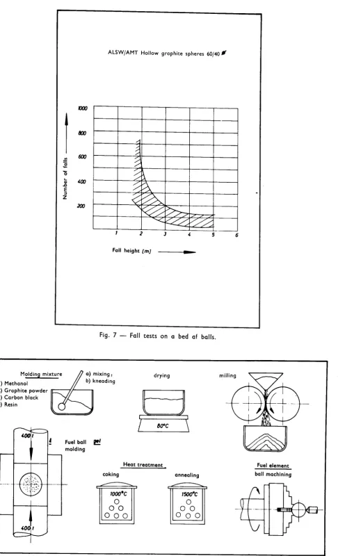
The requirements placed on the drop impact strength of the elements
are fairly high. They must 0e able to withstand at least 50 drops
from a height of 2 m. This is a requirement which is reflected in
the fabrication costs, since not all types of graphite fulfil these
conditions. A more stringent requirement was at one time imposed
by the pneumatic feed unit in the AVR reactor, but we are working
on a solution which will enable the balls to fall on the pebble
bed somewhat less violently. Cheaper types of graphite could then be
used, such as the extruded graphites originally intended.
Other conditions imposed on the fuel elements are good wear
resis-tance, since the formation of graphite dust in the reactor must be
kept as low as possible. The graphite should be as pure as possible,
not only because of the neutron economy, but also on account of the
unwanted catalytic acceleration of the oxidation processes by the
presence of impurities on the surface of the elements. As a result
of the irradiation tests carried out during the past year in
colla-boration with Dragon, the oxidation mechanism is now better
under-stood and our purity requirements can be restricted to less special
elements, such as irono
The fuel consists of coated particles. These are small kernels of
uranium-thorium carbide or oxide,0.2 to
o.6
mm in diameter, onwhich layers of carbon or silicon carbide are deposited from the
gaseous phase. These coated particles have especially good retaining
properties for fission products. The present record is held by
Oak Ridge particles, which at a temperature of 1700° Cup to a
burn-up of 25
%
of the heavy metal used gave off less than 10-6%
of the gaseous fission products formed.
A brief account of the development work carried out in the past