New Approach in Processing of the Infrared Image
Sequence for Moving Dim Point Targets Detection
Mohamed Abdo M., Li Hongzuo
School of Electronics and Information Engineering, Changchun University of Science and Technology, Changchun city, China. Email: [email protected]
Received May, 2013.
ABSTRACT
The development of an efficient moving target detection algorithm in IR-image sequence is considered one of the most critical research fields in modern IRST (Infrared Search and Track) systems, especially when dealing with moving dim point targets. In this paper we propose a new approach in processing of the Infrared image sequence for moving dim point targets detection built on the transformation of the IR-image sequence into 4-vectors for each frame in the se-quence. The results of testing the proposed approach on a set of frames having a simple single pixel target performing a different motion patterns show the validity of the approach for detecting the motion, with simplicity in calculation and low time consumption.
Keywords: IR Image Sequence Processing; Statistical Processing; Dim Point Target Detection
1. Introduction
The detection and tracking of pixel-size moving targets in optical or infrared images have been an active research area for a many years. The pixel-size target is produced when distance between target and imaging system (visual camera or forward looking infrared—FLIR) is long enough. In these circumstances, the target in each frame of images only occupies several pixels, even one pixel.
Early work in IR search and tracking systems utilized algorithms that initially attempted to detect the target spatially in each image, and then used temporal associa-tions for target tracking. Such as the unified framework for IR target detection [1], the correlation based algo-rithm [2], wavelet based algoalgo-rithm [3], mathematical morphology based algorithm [4], image processing tech-niques [5], maximum local contrast [6] and pattern analysis [7], etc. These algorithms are also known as “detect before track” algorithms. Although the “detect before track” algorithms were adequate for applications where the targets were bright compared with the back-ground, they performed poorly with dim targets in severe clutter. In long range surveillance, the target occupies few pixels or even single pixel, and it can be easily con-taminated by noise and evolving clutter.
As for the case of the detection of moving dim point target in images is quite difficult because the target in-tensity in images is low due to the energy transmission loss through long distance, that is, the signal-to-noise
ratio (SNR) is low. Another difficulty of detecting mov-ing dim point target in low SNR images is that it is not easy to accumulate the target energy due to the small size and the motion of the target. Because of these reasons, it has been realized that moving dim point target cannot be detected on the basis of single frame image (DBT algo-rithms). We have to deal with image sequence processing instead of single frame image processing to get better detection results. Thus the “track before detect” rithms were proposed. The “track before detect” algo-rithm is a temporal based algoalgo-rithm which uses multiple frames to incorporate temporal as well as spatial infor-mation. A lot of techniques and algorithms was devel-oped within this concept of processing as 3-D matched filtering [8,9], Velocity filter banks [10,11], multistage IIR filter [12,13], Temporal Profile Based detection [14], Temporal filters [15,16], triple temporal filter (TTF) [17], bilateral TTF [18], dynamic programming [19, 20], se-quential detection [21], parallel spatial and temporal fil-tering [4,22] and Probabilistic data association (PDA) [23], etc.
The main problem that faces any of these algorithms is caused from the huge number of data handling which cause either the computational complexity or the time consumption which for the realization and implementa-tion for real time processing it either cost money or for compensation it comes on the expense of the accuracy.
constitutes. In Section 3, we introduce the proposed new approach and describe its basic steps. In Section 4, a simple practical example of the approach implementation is presented. These results allow us to evaluate the per-formance of the validity of the approach. Finally the conclusion and plans for future work are outlined in Sec-tion 5.
2. Temporal Profile Model
By using a focal plane array (FPA) detector to constantly monitor a scene, each pixel will produce a temporal pro-file over a short period of time. The temporal propro-file in-dicates the variation of the pixel values in this period of time. When a target moves across the pixel, a pulse-like shape disturbance is created on the temporal profile. The width of the pulse will be inversely proportional to the target velocity. Its height above (or depth below) the background depends on its differential intensity with respect to the background.
The pixels that see clear sky or other features constant in time will have temporal profiles that usually behave like a constant mean value plus white noise. Stationary or very large slow moving clutter will also appear as a slowly varying mean plus the same random noise process. Pixels affected by cloud edges or other difficult clutter features will have less regular temporal behaviors. A pixel affected by a small moving target will have a pulse-like shape on the temporal profile, which is distinct from that of the cloud clutter and clear sky [14, 18, 24].
2.1. Static Background
Pixels seeing static background or slow moving objects such as clear sky and the inner portions of cloud have approximately constant intensities. Intensity variation is often caused by random noise. Therefore, the temporal profile of pixels seeing a static background can be mod-eled as a constant plus a low level of random noise. The random noise can be effectively modeled by a Gaussian distribution.
I t C w t (1)
where x(t) is the intensity value of pixel at time t, C is the constant value, w(t) is the random noise assumed to be Gaussian with zero mean and variance 2.
s
σ
2.2. Cloud Edge
Pixels seeing a cloud edge have the temporal profile modeled by a first-order Markov model.
I t I t 1 n t (2)
where n(t) is assumed independent with normal density, zero mean, and variance 2.
c
σ
2.3. Target
Pixels that see a target have intensities that are distinct from those of the cloud clutter and clear sky. The intensi-ties temporal profile of small targets and the background are different: either colder or hotter than the surroundings. As the target moves across these pixels, there will be a disturbance signal on the temporal profile. The width and height of the disturbance signal is related to the target velocity and intensity respectively. Therefore, the tem-poral profile of the target can be modeled by su-per-imposing a disturbance signal on the background.
I t B t T t
(3)where T(t) is the disturbance signal generated when tar-get move across the starring pixel. B(t) is the background intensity related to the position where the target is lo-cated. If the target appears on a static background, then B(t) is the intensity of the static background, else it is cloud edge.
T(t) can be modeled as an independent Gaussian signal with higher variance and mean value reflecting the tem-perature of the target and can be represented as follows:
T t c x t
(4)where, c is the background intensity, Δt is time of target entering and exit the starring pixel, x( ) is normal Gaussian function which exists during Δt, with mean μ and variance . f(t) has a constant value of c when the target does not exist. The value of mean μ is either higher or lower relative to background intensity c to reflect the temperature difference between target and the surround-ings. The variance is higher than the process noise variance for static object to reflect the disturbance signal caused by target moving across the starring pixel.
t 2 t σ 2 t σ
So in general the observation model of infrared image sequence can be described as follows:
f x, y, k
B x, y, k T x, y, k N x, y, k with target B x, y, k N x, y, k without target
(5)
where f x, y, k
represents the intensity of infrared image sequences, B x, y, k
is intensity of background clutter, which is the main component in sequences,
N x, y, k is the intensity of noise generating in focal plane, and T x,
y, k
is the target components when it appears. x,y in above expressions respectively represent the spatial coordinate in focal plane (x=l,2,…,M, y=l,2,…,N for an image of size MxN) and k is temporal coordinate in frames ( k=l,2,..,K).3. The Proposed Approach
and D Diagonals (same for both right and left diagonals), Where D is the number of diagonals in a single frame (Figure ), which can be simply calculated by
D=(M+N)-1 (6)
The proposed approach mainly perform a transforma-tion of the every single IR-image frame of N rows by M columns pixels is converted into 4-vectors, Horizontal Vector with (1xM) cells, Vertical Vector with (1xN) cells, Right Diagonal Vector with (1xD) and the Left Diagonal Vector with (1XD) cells. Each cell of those vectors is the standard deviation value of the corresponding vertical columns pixel, horizontal row pixels, Left Diagonal pix-els and Left Diagonal pixpix-els respectively. Figure and Figure shows an illustration for the process of creating
the 4-vectors (Horizontal - Vertical – Right Diagonal – Left Diagonal).
The standard deviation values are calculated using the population standard deviation
2V
v 1 I x, y, v μ
σ
V
(7)where the is the pixel intensity, x, y are the
pixel position, v is the pixel frame number, V is the total number of pixels (V=N for rows and diagonals, M for columns),
I x, y, v
is the average of the pixels to have their standard deviation calculated.
Figure 1. Sample of FPA Pixels and the description of the Columns, Rows, Left Diagonals and Right Diagonals.
During the calculation of the Diagonals standard de-viation some diagonals will contain less number or pixels, so to normalize the standard deviation value for all di-agonals we perform zeroing for shorter didi-agonals as ex-plained in Table (Figure ), where the Added Zeroing
pixels number different from diagonal to another ac-cording to the number of existing diagonal pixels.
Table 1. Diagonal Standard deviation calculation. Population standard deviation # of
pixels Before Zeroing After Zeroing shortest
diagonal 1
2 1
v 1I x, y,v μ
1
N 2
v 1I x, y, v μ
N
longest
diagonal N
2 1
v 1I x, y, v μ
N
Figure 2. Illustration of Horizontal/Vertical Vectors crea-tion process.
Figure 3. Illustration of Right/Left Diagonal Vectors crea-tion process.
2 N
v 1I x, y, v μ
N
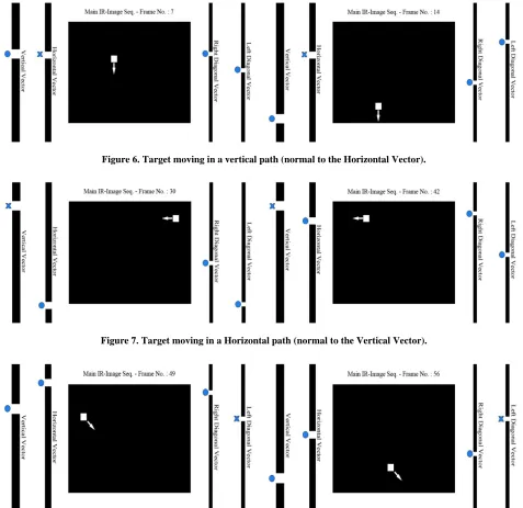
the frames a linear motion through four paths vertical (path 1) , horizontal (path 3), and two diagonal (path 2-4) as shown in Figure. It was clear that the Motion of the
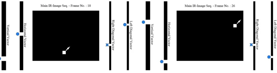
[image:4.595.119.227.85.160.2] [image:4.595.57.534.243.706.2]target will be recognized in at least three of the 4-vectors corresponding to the frame. This change in the 4-vectors will correspond to the disturbance created by the target passing through the corresponding column/row/diagonal. The effect of motion is shown in Figure , Figure , Figure and Figure , it’s also very noticeable that the
target motion disturbance will only be fixed in the case of target motion in a path normal to the vector (marked with (X) on the figures).
Figure 5. Testing Target Paths.
4. Experimental Results
We applied the proposed new approach on a 95 frames each of (15x20) pixels, where a target is moving across
Figure 6. Target moving in a vertical path (normal to the Horizontal Vector).
Figure 7. Target moving in a Horizontal path (normal to the Vertical Vector).
Figure 9. Target moving in a left diagonal path (normal to the right Diagonal Vector).
5. Conclusions
In this paper we propose a new approach in processing the of the Infrared image sequence for moving Dim Point targets detection built on the transformation of the IR-image sequence into 4-vectors for each frame in the sequence. Where these 4-vectors represent that standard deviation of columns, vectors and two diagonals of each image frame pixels. Thus any point on the IR-image can be presented by two different pairs of coordinate either axial or diagonal. We tested the proposed approach on a set of 100 frames with different moving target’s behavior to prove the ability of it to adapt and response to different dim small targets motion patterns. The test results show a great performance beside its calculations and low time consumption which make them valid to be used in real time detection.
REFERENCES
[1] D. S. Chan, “Unified Framework for IR Target Detection and Tracking,” Proceedings of SPIE 1698, Signal and Data Processing of Small Targets 1992, 1992, pp. 66-76. doi:10.1117/12.139403
[2] R. J. Liou and M. R. Azimi-Sadjadi, "Dim Target Detec-tion using High Order CorrelaDetec-tion Method," Aerospace and Electronic Systems, IEEE Transactions on, Vol. 29, 1993, pp. 841-856.doi:10.1109/7.220935
[3] G. Boccignone, A. Chianese and A. Picariello, "Small Target Detection using Wavelets," in Pattern Recognition, 1998. Proceedings. Fourteenth International Conference on, Vol. 2, 1998, pp. 1776-1778.
[4] J. F. o. Rivest and R. Fortin, "Detection of Dim Targets in Digital Infrared Imagery by Morphological Image Proc-essing," Optical Engineering, Vol. 35, pp. 1886-1893, 1996.doi:10.1117/1.600620
[5] T. J. Patterson, D. M. Chabries and R. W. Christiansen, "Image Processing For Target Detection Using Data From A Staring Mosaic Ir Sensor In Geosynchronous Orbit," Optical Engineering, Vol. 25, pp. 251-258, 1984.
[6] Y. Jihui, K. Yongjin, L. Boohwan, K. Jieun and C. Byungin, "Improved Small Target Detection for IR Point Target," in Infrared, Millimeter, and Terahertz Waves, 2009. IRMMW-THz 2009. 34th International Conference
on, 2009, pp. 1-2.
[7] N. C. Mohanty, "Computer Tracking of Moving Point Targets in Space," Pattern Analysis and Machine Intelli-gence, IEEE Transactions on, Vol. PAMI-3, pp. 606-611, 1981.doi:10.1109/TPAMI.1981.4767153
[8] I. S. Reed, R. M. Gagliardi and H. M. Shao, "Application of Three-Dimensional Filtering to Moving Target Detec-tion," Aerospace and Electronic Systems, IEEE Transac-tions on, vol. AES-19, 1983, pp. 898-905.
doi:10.1109/TAES.1983.309401
[9] I. S. Reed, R. M. Gagliardi and L. B. Stotts, "Optical Moving Target Detection with 3-D Matched Filtering," Aerospace and Electronic Systems, IEEE Transactions on, vol. 24, 1988, pp. 327-336.doi:10.1109/7.7174
[10] A. D. Stocker and P. D. Jensen, "Algorithms and Archi-tectures for Implementing Large-velocity Filter Banks," Proceedings of SPIE 1481, Signal and Data Processing of Small Targets 1991, 1991, pp. 140-155.
[11] W. B. Kendall, A. D. Stocker and W. J. Jacobi, "Velocity Filter Algorithms for Improved Target Detection and Tracking with Multiple-Scan Data," Proceedings of SPIE 1096, Signal and Data Processing of Small Targets 1989, pp. 127-139, 1989.
[12] H. E. Rauch, W. I. Futterman and D. B. Kemmer, "Back-ground Suppression and Tracking with A Staring Mosaic Sensor," Optical Engineering, 1981, Vol. 20, pp. 201103-201103.doi:10.1117/12.7972672
[13] E. T. Lim, S. D. Deshpande, C. W. Chan and R. Venkateswarlu, "Dim Point Target Detection in IR Im-agery using Multistage IIR Filter," Proceedings of SPIE 4025, Acquisition, Tracking, and Pointing XIV, 2000, pp. 194-202.
[14] D. Liu, J. Zhang and W. Dong, "Temporal Profile Based Small Moving Target Detection Algorithm in Infrared Image Sequences," International Journal of Infrared and Millimeter Waves, Vol. 28, 2007, pp. 373-381.
[15] J. Silverman, J. M. Mooney and C. E. Caefer, "Tracking point targets in cloud clutter," Proc. SPIE 3110, 10th Meeting on Optical Engineering in Israel, 1997, pp. 496-507.doi:10.1117/12.281362
[17] J. M. Mooney, J. Silverman and C. E. Caefer, "Point Tar-get Detection in Consecutive Frame Staring Infrared Im-agery with Evolving Cloud Clutter," Optical Engineering, vol. 34, pp. 2772-2784, 1995.
doi:10.1117/12.210757
[18] W. Zhang, J. Gong, Q. Hou, and C. Bian, "Point Target Detection Based on Nonlinear Spatial-temporal Filter in Infrared Image Sequences and Its Analysis," Proc. SPIE 8558, Optoelectronic Imaging and Multimedia Technol-ogy II, 2012, pp. 85582E-85582E.
doi:10.1117/12.2000626
[19] Y. Barniv, "Dynamic Programming Solution for Detect-ing Dim MovDetect-ing Targets," Aerospace and Electronic Systems, IEEE Transactions on, Vol. AES-21, 1985, pp. 144-156.doi:10.1109/TAES.1985.310548
[20] J. F. Arnold and H. Pasternack, "Detection and Tracking of Low-observable Targets through Dynamic Program-ming," Proc. SPIE 1305, Signal and Data Processing of
Small Targets 1990, 1990, pp. 207-217.
[21] S. D. Blostein and T. S. Huang, "Detecting Small, Mov-ing Objects in Image Sequences usMov-ing Sequential Hy-pothesis Testing," Signal Processing, IEEE Transactions on, Vol. 39, 1991, pp. 1611-1629.doi:10.1109/78.134399 [22] S. Pohlig, "Spatial-temporal Detection of Electro-optic
moving Targets," Aerospace and Electronic Systems, IEEE Transactions on, Vol. 31, 1995, pp. 608-616. doi:10.1109/7.381909
[23] A. Hamdulla and L. Xingke, "High-Resolution Bayes Detection of Dim Moving Point Target in IR Image Se-quence Using Probabilistic Data Association Filter," in Computer Science and Software Engineering, 2008 In-ternational Conference on, 2008, pp. 365-368.