Attitude Control of a Quadrotor with Optimized PID
Controller
Hossein Bolandi1, Mohammad Rezaei1, Reza Mohsenipour2,
Hossein Nemati1, Seed Majid Smailzadeh1
1
Electrical Engineering Department, Iran University of Science and Technology, Tehran, Iran 2
East Tehran (Qiam Dasht) Branch, Islamic Azad University, Tehran, Iran Email: [email protected], [email protected], [email protected],
[email protected], [email protected]
Received October 17, 2012; revised December 1, 2012; accepted December 9,2012
Copyright © 2013 Hossein Bolandi et al. This is an open access article distributed under the Creative Commons Attribution License, which permits unrestricted use, distribution, and reproduction in any medium, provided the original work is properly cited.
ABSTRACT
A new approach to control, stabilization and disturbance rejection of attitude subsystem of quadrotor is presented in this article. Analytical method is used to tune conventional structure of PID controller. SISO approach is implemented for control structure to achieve desired objectives. The performance of the designed control structure is evaluated through time domain factors such as overshoot, settling time and integral error index, and robustness. A comparison is done between designed controller and back-step controller applied to main model of quadrotor. The results of simulation show the effectiveness of designed control scheme.
Keywords: Modeling; Optimization; PID Control; Quadrotor
1. Introduction
Recent technological advances in energy storage devices, sensors, actuators and information processing have boost- ed the development of Unmanned Aerial Vehicle (UAV) platforms with significant mission capabilities [1,2]. Unmanned aerial vehicles are important when it comes to perform a desired task in a dangerous and/or inaccessible environment. More recently, a growing interest in un- manned aerial vehicles (UAVs) has been shown among the research community [3]. The rotorcraft UAVs pose a set of advantages compared to the fixed wing UAVs, such as hovering, vertical takeoff and landing and ag- gressive maneuvering. Within the family of the rotor- crafts, Unmanned Quadrotor Helicopters (UQHs) have gained increasing attention among scientists and engi- neers [4]. A quadrotor is a 4-rotor vertical takeoff and landing vehicle that has the maneuvering abilities of tra- ditional helicopters with significantly lower mechanical complexity. This low complexity increases dependability while reducing the cost of manufacturing, operation, and maintenance [5]. Quadrotor is usually used to develop control laws. This kind of helicopter tries to reach a sta- ble hovering and flight, using the equilibrium forces produced by four rotors [6]. Quad rotors are therefore becoming a promising option for various unmanned
military and civilian applications [5]. One of the advan- tages of the quadrotor configuration is its payload capac- ity. As a drawback, this type of UAV presents a weight and energy consumption augmentation due to the extra motors [7].
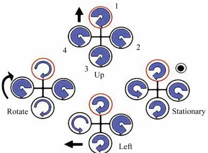
A Quadrotor Configuration
One can describe the vehicle as having four propellers in cross configuration. The two pairs of propellers (1, 3) and (2, 4) turn in opposite directions by varying the rotor speed; one can change the lift force and create motion. Thus, increasing or decreasing the four propeller’s speeds together generates vertical motion. Changing the 2 and 4 propeller’s speed conversely produces roll rota- tion coupled with lateral motion. Pitch rotation and the corresponding lateral motion are resulted from changing 1 and 3 propeller’s speed conversely. Yaw rotation is more subtle, as it results from the difference in the counter- torque between each pair of propellers [2]. Figure 1 de- scribes concept motions of quadrotor.
Figure 1. Quadrotor concept motions description.
cluding under-actuation, strong coupling, multi input/ multi output and unknown nonlinearities [9]. The auto- matic control of a quadrotor UAV is not a straight on mainly due to its under-actuated properties [10] and it is difficult to control all these six outputs with only four control inputs. Moreover, uncertainties associate with dy- namic model also bring more challenge for control de- sign [11].
In some papers the quadrotor helicopter has also been controlled using a linear controllers based on lineariza- tion models. In [12] two control techniques were com- pared, a PID and a Linear Quadratic Regulator (LQR), where a linearization model was considered to design the PID controller. The development of the LQR was based on a time variant model. The time-optimal control prob- lem of a hovering quadrotor helicopter is addressed in [13]. Instead of utilizing the Pontryagin’s Minimum Prin- ciple (PMP), in which one needs to solve a set of highly nonlinear differential equations, a nonlinear program- ming (NLP) method is proposed. In this novel method, the count of control steps is fixed initially and the sam- pling period is treated as a variable in the optimization process. Nonlinear control problems for hovering qua- drotor helicopters such as feedback linearization control and back-stepping control laws were studied in [14]. Back-stepping based techniques are utilized to design a nonlinear adaptive controller which can compensate for the mass uncertainty of the vehicle. Lyaponve based sta- bility analysis shows that the proposed control design yields asymptotic tracking for the UAV’s motion in x, y, z direction and the yaw rotation, while keep the stability of the closed loop dynamics of the quadrotor UAV [11]. In [15] the rotor dynamics were considered in the model. The model was split up into two subsystems: the angular rotations and the linear translations and then back-step- ping and sliding mode techniques were used to control the helicopter. In [7] a control law based on a standard back-stepping approach for translational movements and a nonlinear
combined to perform path following in the presence of external disturbances and parametric uncertainties. How- ever, this strategy is only able to reject sustained distur- bances applied to the rotational motion both path follow- ing and stabilization problems. Time-optimal problems of control systems have attracted the attention of many researchers, especially in aerospace [16] and robotics [17] in the past few years. In this paper, we apply SISO con- trol structure to achieve desired objectives such as: sta- bility, control, robustness and disturbance rejection for attitude subsystem of quadrotor which is in fact an un- stable plant. To achieve best time domain performance, SISO approach is used, the advantage of this strategy is that in every loop, the desired performance of loop is evaluated and if it is necessary, just the parameters of one controller would be manipulated. This paper is organized as follows. The dynamic model of quadrotor is given in Section 2. In Section 3, the control strategy is exposed. Simulation results are presented in Section 4. Finally, the major conclusion of the paper is drawn in Section 5.
2. Quadrotor Modeling
2.1. Description
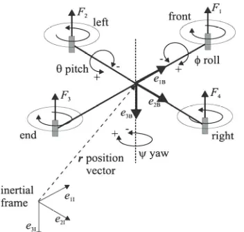
The quadrotor has four rotors that are controlled inde- pendently. The movement of the quadrotor results from changes in the speed of the rotors. The structure of qua- drotor in this paper is assumed to be rigid and symmetri- cal, the center of gravity and the body fixed frame origin are coincided, the propellers are rigid and the thrust and drag forces are proportional to the square of propeller’s speed. Figure 2 presents the structure of quadrotor and relative coordinate systems.
2.2. Kinematics of Quadrotor
The earth-fixed inertial reference frame is
1I, 2I, 3I
I
E e e e and the body-fixed reference frame is
, ,
E e e e
T, ,
1B 2B 3B
B . The absolute position of the quadrotor
is described by X x y z
T , ,and its attitude by the
H controller to stabilize the helicopter are
Euler angles Θ , used corresponding to aero- nautical convention. The attitude angles are respectively called Yaw angle ( rotation around z-axis), Pitch an- gle ( rotation around y-axis) and Roll angle ( rota- tion around x-axis). Let V
u v, ,
TEb denote the
T, , b
p q r E
Ω
linear velocity vector and denote the angular velocity vector of the airframe expressed in the body-fixed-frame. The relation between the velocities vectors
V,
and
X ,
is given by
1
Θ
Θ Θ Ω
X R V
M (1)
Θ
Figure 2. The structure of quadrotor and relative coordi- nate systems.
formation rotation and the rotation velocity matrices be- tween Eb and EI:
s s
b i zxy
s s s c c s s c
c s c c
c s c s c s
c s s c
s
s s c c
R Θ 0 0 0 1
c c s
s c c
s
2 2 2 2
2 3 4
2 2
2
2 2
1
2 2 2 2
4 1 3
(2)
Θ M (3)
where C·= cos(·) and S·= sin(·).
2.3. Dynamics of Quadrotor
Two different methods have been investigated to achieve dynamics of quadrotor. One can either use the Lagran- gian equation or the Newton’s law. Let’s explain the sec- ond method which is more comprehensible.
The quadrotor is controlled by independently varying the speed of the four rotors. Hence four inputs are de- fined as follow:
1 1 2 4 3 3 4 2 u b u b u b u d (4)
The quadrotor motion equations can be expressed with Newton’s law: 4 2 1 0 0 0 1 i i b
m
0 1b i zxy
X g
R (5)
1
1
1
x S C u m
y S u m
z C C u m g
(6)
Also, to relate Euler angular rates to body angular rates, we have to use the same order of rotation. This gives rise to:
cos sin 0
sin cos
0
cos cos
sin tan cos tan 1 p q r (7) By differentiating, 0 0 0 0 sin 0 0
t t 1
C t C t C C p S C q C C r S C p q r (8) I is the inertia matrix of the vehicle and
2
3 4 d d u p I
l u q
t r u I I
2 1 3 4 u pq l u
r u
I I
0 0 0 0 0 0 xx yy (9)
. (10)
Assuming that the structure is symmetrical:
zz I I I
I . (11)
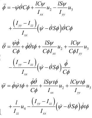
In some papers, the second term of the right side of the Equation (10),
I
is neglected [18]. This ap- proximation can be made by assuming that: the angular rate about the z axis, r, is small enough to be neglected
Ixx Iyy
Let’s just assume, for the moment, that the moments of inertia along the x axis and y axis are equaled [19].
2 3 2 3 2 3 yy yy yy u S C lC uI C I
I C
lC t u I
u S t
4 xx yy zz xx xx yy zz xx xx yy zz zz xx lC lS C u I I I I I lS t u C C I I S lS t t u C I I I l I I (12)
3. Control Strategy
The dynamic model of quadrotor developed in Section 2 will be linear around hovering situation. Hence the gyro- scopic effects won’t be taken into consideration in the control design. In this paper, Taylor method is used to linear the model of quadrotor, the operation values of states and inputs around hovering mode are:
02 0
1 0
0 0
0,u u
m g z u C C
3 0 u4 0 0
(13)
The linear model of quadrotor is given as:
1 1 x g y g z u m (14) 2 3 4 xx yy zz l u I l u I l u I , , (15)
As the dynamic model shows, attitude subsystem of quadrotor, Equation (15),
, ,
are forced directly by input signals. The transfer function of
, ,
is a sec- ond order with two poles on the origin, so the system is inherently unstable. PID controllers will be designed to stabilize and control the attitude subsystem of quadrotor.
3.1. PID Control
Proportional-plus-integral-plus-derivative (PID) control-
lers are widely used in the industry [20,21]. The main reason is its relatively simple structure, which can be easily understood and implemented in practice [22]. The widespread use of PID-type controllers in industries has affected efforts in the design and tuning of conventional PID controllers so as to achieve an optimal performance for the control system [23].
3.2. SISO Approach
As the Linear model of quadrotor shows, it is possible to use SISO approach for controlling attitude components. The transfer function of
, ,
is a second order with two poles on the origin. These components are directly affected by three inputs. One can consider block diagram for
, ,
components. Figure 3 shows control block diagram that can be used for each one of
, ,
com- ponents. As shown in Figure 3, one controller should be designed for each one of
, ,
to achieve desired
d d d
directly. The g(s) model is assumed a sec- ond-order:
1 1
2 1
k g s
s s
(16)
And the desired PID structure is considered:
1 1 i c d i T sC s k T s
T s
(17)
3.3. PID Tuning
Tuning of PID controllers has been attracting interest for six decades. Numerous methods suggested so far try to accomplish the task by making use of different represen- tations of the essential aspects of the process behavior [24]. Among the well-known formulas are the Ziegler- Nichols rule, the Cohen-Coon method, IAE, ITAE, and internal model control. These formulas are surveyed in [25]. Controller parameters are usually tuned so that the closed-loop system meets the following three objectives:
1) Stability and stability robustness, usually measured in the frequency domain;
2) Transient response, including rise time, overshoot, and settling time;
[image:4.595.88.244.87.287.2]3) steady-state accuracy [26].
[image:4.595.316.532.633.719.2]In this paper direct synthesis method [27] is used to drive PI-settings or PID-settings for set points. Optimiza- tion-based method can be regarded as a special type of optimal control.
For the system in Figure 3, the close loop set point response is:
1s
g s c s
y g s c s
y
(18)
The idea of direct synthesis is to specify the desired close loop response and solve for corresponding control- ler.
desigerd1 1
1
s
y y
c
1
c s g s
(19)
The g(s) model is assumed a second-order in Equation (16) and the desired close loop transfer function is a first order whit time constant:
de
y
sired 1
1
s c
y s (20) Substituting Equations (20) and (16) into (19) gives a “smith predictor” controller [28]:
1 1
2 1
1c
s s
k s
c s
(21)
c
is the desired close-loop time constant and is the sole tuning parameter for controller. Equation (21) is a series form PID-controller [27-29].
1
1
2
1 1
c c
k k
c
I
D k
T
(22)
3.4. Modifying the Integral Time for Improved Disturbance Rejection
The PID-setting in Equation (21) is desired by consider- ing the set point response and the result must cancel the first order dynamics of the process by selecting the inte- gral time I 1
T
. This is a robust setting witch result in very good response to set points and to disturbance en- tering at process out-put. However, it is well known that for integrating processes, the choice I 1
4
result in a long settling time for input load disturbances [30]. To improve the load disturbance response, the integral time should be reduced, but not too much because otherwise we get slow oscillations caused by having almost two integrators in series. A good tradeoff between distur- bance response and robustness is obtained by selecting the integral time such that the slow oscillations are avoided. So the best choice for integral time is proposed
in [31]:
(23)
I
c
To summarize, the recommended SIMC PID-setting for the double integral process, 1, 2 the parame- ters of PID are:
21 1
4
4
4
c
c
D c
I c
k
k
c
(24)
3.5. Recommended Choice for Tuning Parameter
The value of the desired close loop time constant ccan
be chosen freely, the optimal value of c is determined
by a trade of between:
1) Fast speed response and good disturbance rejection by a small value of c.
2) Stability, robustness and small variation by a large value of c.
An alternative is to use the integral error as a perfor- mance index. The followings are some commonly used criteria based on the integral error for a step set-point response:
00 2 0
2 0
d
d
d
d
IAE e t t
ITAE t e t t
ISE e t t
ITSE te t t
(25)
In this paper IAE criterion is used as an objective function to chose c. Alternatively, a self-learning evo-
lutionary algorithm (EA) can be used to choose c to
meet multiple design objectives in time domain. In this paper the Genetic Algorithm is used for this work.
The best choice for c is obtained from Genetic Al-
gorithm that satisfies minimum value for IAE is: 0.005
c
3.6. Simulation Results
The proposed control strategy has been tested by simula- tion in order to check the performance attained for the stabilization, disturbance rejection and tracking problems with real model of attitude subsystem of quadrotor.
The values of the model parameters used for simula- tions are:
2
2 2
2
2.3535 kg, 9.81 m/s , 0.5 m,
0.1676 kgm , 0.1676 kgm ,
0.2974 kgm
xx yy
zz
m g l
I I
I
Figure 4 shows the result of regulation attitude com- ponent with desired controller vs. the back-step control- ler. As the Figure 4 shows the response of desired con- troller is faster than back-step controller and this matter is so important because attitude subsystem is inner loop in quadrotor plant and when the transitional components
are controlled, the speed of inner loop response plays very important role.
Other objective that is considered in this paper is load disturbance rejection. Figure 5 shows the manner of two controllers to rejection the step disturbance that adds to output.
15
0 0.5 1 1.5 2 2.5 3 -5
0 5 10
(d
e
g
)
Attitude Parameters of Quadrotor
PID (deg) Backstep (deg)
15
0 0.5 1 1.5 2 2.5 3 -5
0 5 10
(d
e
g
)
PID (deg) Backstep (deg)
0 0.5 1 1.5 2 2.5 3 -5
0 5 10 15
Time (s)
(d
e
g
)
PID (deg) Backstep (deg)
Figure 4. Attitude regulation signals of quadrotor.
12
0 0.5 1 1.5 2 2.5 3 3.5 4 4.5 5 -2
0 2 4 6 8
Time (s) 10
(de
g
)
Attitude Parameters of Quadrotor
PID (deg) Backstep (deg)
14
0 0.5 1 1.5 2 2.5 3 3.5 4 4.5 5 -2
0 2 4 6 8 10 12
(d
e
g
)
PID (deg) Backstep (deg)
Tim (s)e 12
0 0.5 1 1.5 2 2.5 3 3.5 4 4.5 5 -4
-2 0 2 4 6 8
Time (s) 10
(d
e
g
)
PID (deg) Backstep (deg)
0 2 4 6 8 10 12 14 16 18 20 -20
0 20
(d
e
g
)
Attitude Parameters of Quadrotor
d (deg) PID (deg) Backstep (deg)
0 2 4 6 8 10 12 14 16 18 20 -20
0 20
(d
e
g
) d (deg)
PID (deg) Backstep (deg)
0 2 4 6 8 10 12 14 16 18 20 -20
0 20
Time (s)
(d
e
g
) d (deg)
[image:7.595.163.433.87.228.2]PID (deg) Backstep (deg)
Figure 6. Tracking of the predefined trajectory attitude components of quadrotor.
The results show that desired controller rejects distur- bance in minimum time. There is an overshoot in re- sponses that is usual because of the fast response. Finally we need a fast response because of the reason that previ- ously mentioned.
In Figure 6 tracking of the predefined trajectory for attitude components with two controllers are surveyed. As shown in Figure 6, the tracking of the predefined trajectory is done with two controllers so good. In first seconds the desired controller has better response than back-step controller.
4. Conclusions
In this paper a SISO control structure of quadrotor is presented. Analytical optimization method is used to tune a conventional PID controller for stabilization and dis- turbance rejection of quadrotor. The time domain per- formance of designed control structure is evaluated with IAE objective function. The results of simulation in Si- mulink/Matlab software, illustrate the efficient of ap- plied control strategy.
Future works will focus on model predictive control design for quadrotor UAV to has ideal tracking and sta- bilization.
REFERENCES
[1] K. Valavanis, “Advances in Unmanned Aerial Vehicles: State of the Art and the Road to Autonomy, ser. Micro- processor-Based and Intelligent Systems Engineering,” Springer-Verlag, Berlin, 2007.
[2] S. Bouabdallah and R. Siegwart, “Back-Stepping and Slid- ing-Mode Techniques Applied to an Indoor Micro Qua- drotor,” Proceedings of the IEEE International Confer-
ence ofRobotic and Automatic, Barcelona, April 2005, pp. 2451-2456.
[3] A. Tayebi and S. McGilvray, “Attitude Stabilization of a VTOL Quadrotor Aircraft,” IEEE Tranactions on Control
Systems Technology, Vol. 14, No. 3, 2006, pp. 562-571. doi:10.1109/TCST.2006.872519
[4] K. Alexis, G. Nikolakopoulos and A. Tzea, “Constrained
Optimal Attitude Control of a Quadrotor Helicopter Sub- ject to Wind-Gusts: Experimental Studies,” American Con-
trol Conference, Baltimore, 30 June-2 July 2010, pp. 4451- 4455.
[5] H. Yang, R. Abousleiman, B. Sababaha, E. Gjoni, D. Korff and O. Rawashded, “Implementation of an Auto- nomous Surveillance Quadrotor System,” AIAA Infotech
Aerospace Conference, Seattle, 6-9 April 2009, pp. 2009- 2047.
[6] G. V. Raffo, M. G. Ortega and F. R. Rubio, “An Integral Predictive/Nonlinear H∞ Control Structure for a Quadro- tor Helicopter,” Journal of Automatica, Vol. 46, No. 1, 2009, pp. 29-39. doi:10.1016/j.automatica.2009.10.018 [7] G. V. Raffo, M. G. Ortega and F. R. Rubio, “Back-Step-
ping/Nonlinear H∞ Control for Path Tracking of a Quad- Rotor Unmanned Aerial Vehicle,” Proceedings of the
American Control Conference,Seattle, 11-13 June 2008, pp. 3356-3361.
[8] P. Castillo, R. Lozano and A. Dzul, “Modelling and Con- trol of Mini Flying Machines,” Springer-Verlag, London, 2005.
[9] A. Das and K. S. Lewis, “Dynamic Inversion with Zero- Dynamics Stabilisation for Quadrotor Control,” IET Con-
trol Theory and Application, Vol. 3, No. 3, 2009, pp. 303-314. doi:10.1049/iet-cta:20080002
[10] A. Mokbari and A. Benallegue, “Dynamic Feedback Con- troller of Euler Angles and Wind Parameters Estimation for a Quadrotor Unmanned Aerial Vehicle,” Proceedings of the IEEE International Conference of Robotic and Automatic, New Orleans, 26 April-1 May 2004, pp. 2359- 2366.
[11] M. Huang, B. Xian, C. Diao, K. Yang and Y. Fung, “Adap- tive Tracking Control of Under actuated Quadrotor Un- manned Aerial,” American Control Conference, Balti-more, 2010, pp. 2076-2081.
[12] S. Bouabdallah, A. Noth and R. Siegwart, “PID vs LQ Control Techniques Applied to an Indoor Micro Quadro- tor,” Proceedings of the IEEE International Conference
of Intelligent Robots Systems, Sendai, 28 September-2 October 2004, pp. 2451-2456.
115-135. doi:10.1007/s10846-005-9015-3
[14] V. Mistler, A. Benallegue and N. K. M’Sirdi, “Exact Linearization and Noninteracting Control of a 4 Rotors Helicopter via Dynamic Feedback,” Proceedings of the
IEEE International Workshop on Robotic and Human In- teractive Communication, Bordeaux, 18-21 September 2001, pp. 586-593.
[15] S. Bouabdallah, P. Murrieri and R. Siegwart, “Design and Control of an Indoor Micro Quadrotor,” Proceedings of
the IEEE International Conference of Robotic and Auto- matic, New Orleans, 26 April-1 May 2004, pp. 4393- 4398.
[16] Y. W. Jan and J. C. Chiou, “Minimum-Time Spacecraft Manoeuvre Using Sliding-Mode Control,” Acta Astronaut, Vol. 54, No. 1, 2003, pp. 69-75.
doi:10.1016/S0094-5765(03)00194-2
[17] W. Wu, H. Chen and P. Y. Woo, “Optimal Motion Plan- ning for a Wheeled Mobile Robot,” Proceedings of the
IEEE International Conference of Robotic and Automatic, Detroit, 10-15 May 1999, pp. 41-46.
[18] S. L. Waslander, G. M. Hoffmann, J. S. Jang and C. J. Tomlin, “Multi Agent Quadrotor Test Bed Control De- sign Integral Sliding Mode vs. Reinforcement Learning,”
Proceedings of the IEEE International Conference of In-telligent Robots Systems, Alberta, 2-6 August 2005, pp. 3712-3717.
[19] C. Balas, “Modeling and Linear Control of a Quadrotor,” M.S. Thesis, Cranfield University, Bedford, 2007. [20] K. J. Astrom and T. Hagglund, “Automatic Tuning of
Simple Regulators with Specifications on Phase and Am- plitude Margins,” Journal ofAutomatica, Vol. 20, No. 5, 1984, pp. 645-651. doi:10.1016/0005-1098(84)90014-1 [21] W. K. Ho, O. P. Gan, E. B Tay and E. L. Ang, “Perform-
ance and Gain and Phase Margins of Well-Known PID Tuning Formulas,” IEEE Transactions on Control System
Technology, Vol. 4, No. 4, 1996, pp. 473-477. doi:10.1109/87.508897
[22] Q. G. Wang, T. H. Lee, H. W. Fung, Q. Bi and Y. Zhang, “PID Tuning for Improved Performance,” IEEE Transac-
tions on Control Systems Technology, Vol. 7, No. 4, 1999, pp. 457-465. doi:10.1109/87.772161
[23] Y. C. Cheng and C. Hwang, “Stabilization of Unstable First-Order Time-Delay,” Journal of the Chinese Institute
of Engineers, Vol. 29. No. 2, 2006, pp. 241-249. doi:10.1080/02533839.2006.9671121
[24] D. Vrancic, S. Strmcnik, J. Kocijan and P. B. M. Oliveira, “Improving Disturbance Rejection of PID Controllers by Means of the Magnitude Optimum Method,” ISA Trans-
actions, Vol. 49, No. 1, 2009, pp. 47-56. doi:10.1016/j.isatra.2009.08.002
[25] Y. Li, K. H. Ang, G. Chong, W. Feng, K. C. Tan and H. Kashiwagi, “CAutoCSD-Evolutionary Search and Opti- misation Enabled Computer Automated Control System Design,” International Journal of Automatic and Com-
puter, Vol. 1, No. 1, 2004. pp. 76-88. doi:10.1007/s11633-004-0076-8
[26] C. Lin, Q. G. Wang, Y. He, G. Wen, X. Han and G. Z. H. Z. Li, “On Stabilizing PI Controller Ranges for Multi- variable Systems,” Chaos, Solitons and Fractals,Vol. 35, No. 3, 2008, pp. 620-625.
[27] C. A. Smith and A. B. Corripio, “Principles and Practice of Automatic Process Control,” John Wiley & Sons, New York, 1985.
[28] O. J. Smith, “Closer Control of Loops with Dead Time,”
Chemistry Engineering Progress, Vol. 53, No. 5, 1957, pp. 217-219.
[29] D. E. Rivera, M. Morari and S. Skogestad, “Internal Model Control. 4. PID Controller Design,” Industrial &
Engineering Chemistry Research Process Design & De- velopment, Vol. 25, No. 1, 1986, pp. 252-265.
doi:10.1021/i200032a041
[30] I. L. Chien and P. S. Fruehauf, “Consider IMC Tuning to Improve Controller Performance,” Chemistry Engineer- ing Progress, Vol. 86, No. 10, 1990, pp. 33-41.
[31] S. Skogestad, “Simple Analytic Rules for Model Reduc-tion and PID Controller Tuning,” Journal of Process