International Journal of Emerging Technology and Advanced Engineering
Website: www.ijetae.com (ISSN 2250-2459, ISO 9001:2008 Certified Journal, Volume 6, Issue 11, November 2016)
174
Open Software One-Step Coupled Neutronics and CFD
Thermalhydraulics Calculation
Vitor Silva
1, Andre Campagnole dos Santos
2, German Theler
3, Claubia Pereira
41,2Centro de Desenvolvimento da Tecnologia Nuclear, Comissao Nacional de Energia Nuclear, Av. Pres. Antônio Carlos, 6627 -
30270-901 Belo Horizonte, MG, Brazil
3Seamplex, Santa Cruz 205, 2300, Rafaela, Argentina 1,4
Departamento de Engenharia Nuclear (DEN), Universidade Federal de Minas Gerais (UFMG), Av. Pres. Antonio Carlos, 6627 - 30270-901 Belo Horizonte, MG, Brazil
Abstract--A one-step coupled neutronic and CFD thermal-hydraulic methodology is presented. The contribution proposed goes toward the use of the computational fluid dynamics (CFD) software OpenFOAM and the flexible reactor core analysis code milonga to perform coupled calculations for advanced nuclear reactor analysis. The developed methodology was applied to simulate a fuel pin from CDTN’s TRIGA-IPR-R1 reactor and asses its behavior in steady-state mode for different power levels. A set of two-group macroscopic cross-sections data was generated using WIMSD-5B code for different expected temperatures. The results show that this coupled system gives consistent results, encouraging system further development and its use for full core simulation.
Keywords—Coupling, milonga, Neutronics, OpenFOAM, CFD, Thermal-hydraulics.
I. INTRODUCTION
The goal is to present a coupled neutronic and Computational Fluid Dynamics (CFD) thermal-hydraulic methodology for nuclear reactors calculations. The thermalhydraulic calculations are performed by the CFD toolbox called OpenFOAM [1]. For neutronic calculations, a nuclear reactor core analysis code called milonga is used to solve the steady-state multigroup neutron diffusion equation [2]. Both codes solve the discretized equations for an unstructured mesh using finite volumes method. In this coupled framework, both codes use the same mesh for domain discretization, allowing both codes to solve their problems with the same degree of detail.
With the increase of computational power and parallel processing capability observed over the past decade, numerical simulations using highly discretized domains, as finite volume CFD, has grown and is quickly becoming the main numerical tool for analysis in engineering. With this new available capacity, the trend is to perform increasingly complex simulations coupling different codes so that multi-physics analysis can be performed, increasing the understanding of the behaviors of a physical system as a whole [3]. For the nuclear field, researchers now strive to achieve complex coupling of neutronics and thermal-hydraulics as their physics is intrinsically connected by feedback effects.
The objective of this paper is to present a one-step coupling of open source neutronic and CFD thermal-hydraulic codes. The decision to adopt open software is so that the development can be, freely distributed so it can be used and improved by the nuclear academic and industrial communities.
II. METHODOLOGY
International Journal of Emerging Technology and Advanced Engineering
Website: www.ijetae.com (ISSN 2250-2459, ISO 9001:2008 Certified Journal, Volume 6, Issue 11, November 2016)
175
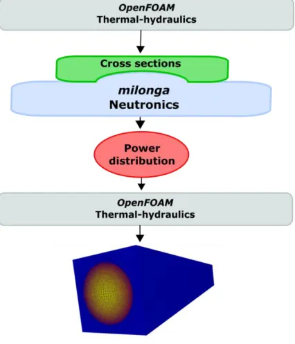
Figure 1: Coupling methodology schematic.
The methodology developed by DEN/UFMG [4,12] for cross-sections processing using WIMSD-5B code was applied in this work. In this methodology, a 69 groups cross-section library generated from ENDF-VI is used to generate a set of two-group cross-sections for three different materials, coolant, cladding, and fuel, at different temperatures, corresponding to the modelled fuel element temperatures variation.
In the following section, details of the methodology and simulations performed are presented.
A. Geometrical model and mesh
The coupled methodology was assessed simulating one of CDTN’s TRIGA IPR-R1 reactor fuel pins and evaluating the physical coherence of the results. This fuel was selected for this paper due to its strong temperature coefficient in terms of reactivity.
[image:2.612.63.276.136.384.2]The geometry of the simulated cylindrical fuel pin comprised of a 1.78 cm radius fuel with a 1.865 cm external radius aluminum cladding surrounded by a square water section of 4.57 cm, as shown in Fig. 2. The total axial length of the model was 35 cm, equal to the active length of the CDTN’s TRIGA IPR-R1 reactor fuel pins. To simplify the model, no gap between the fuel and the cladding was considered. The volume of water was defined to maintain the same water to fuel ratio found in the reactor core.
Figure 2: Exploded mesh discretization by region
The mesh was generated using Gmsh [5] that is an open source software for three-dimensional unstructured mesh generation compatible with both used software. A 2D mesh for the transversal section of the domain was defined with a global maximum mesh size of 4.0 mm for the whole domain and 0.3 mm local sizing at the cladding with a growth ratio of 1.2. These parameters resulted in a smoothly growing mesh in the 2D plane. The axial mesh was set as 35 extrude mesh layers of the 2D mesh. Some details of the mesh are also shown in Fig. 2.
The use of these parameters resulted in a mesh with 346,675 elements.
B. Thermalhydraulics
OpenFOAM is a C++ library used to create solvers for problems in continuum mechanics and utilities for data manipulation [1]. There is a large array of implemented solvers for CFD simulations that are verified by the
OpenFOAM Foundation and is quickly being adopted by several companies and academic institutes as their main CFD solution. Amongst the available solvers, the
chtMultiRegionSimpleFoam solver [1] was chosen for this work as it couples single phase flow simulations to solid conduction simulation.
The selected solver solves the RANS momentum, continuity and energy conservation equations for the fluid region and energy conservation equation for the solids. A modification of the energy equation for the fuel region was implemented in the code to include a variable source term in the solution. This is one of the main advantages of
OpenFOAM [1] as it allows equations assembly directly using objects in the solver code.
The RANS two equations standard k-ε turbulence model [6] was selected to calculate the turbulent viscosity. The model assumes that the turbulence viscosity is related to the turbulence kinetic energy (k) and dissipation (ε).
Thermo-physical properties are defined for each region as a function of temperature or constant based on the work by Veloso [7], as presented in Tab. I.
Cladding
International Journal of Emerging Technology and Advanced Engineering
Website: www.ijetae.com (ISSN 2250-2459, ISO 9001:2008 Certified Journal, Volume 6, Issue 11, November 2016)
[image:3.612.317.569.222.294.2]176
TABLE I
THERMO-PHYSICAL PROPERTIES.
Material Density
[kg/m3] Specific heat [kJ/kg.K] Conductivity [W/m.K] Viscosity [μPa.s]
Cladding 2705 -
Fuel 6280 -
Coolant 995 4.18 0.62 797
C. Neutronics
The milonga nuclear code is a free and open source piece of software released under GNU license [8]. It heavily relies on other well-known GNU libraries, like GNU Scientific Library [9], bringing to it the robustness of this established software. It solves the steady-state multi-group neutron transport equation using different methods. In the present work, the diffusion approximation method is used. Milonga can discretize the spatial coordinates using either a finite-element or a finite-volumes scheme.
This ability to use finite-volumes discretization schemes over unstructured grids allows the use of the same mesh for both thermal-hydraulics and neutronics. With identical meshes, there is no need of fields mapping or balancing between codes, making coupled calculations straightforward. Despite the inaccurate results and limitations of the diffusion approximation under some circumstances [10], it is the method used in this work due to its relatively fast execution time.
The cross-sections dependence on temperatures does not affect the formulation of diffusion equation as linear since in the iterative calculation all coefficients are constant during time steps.
Milonga works by reading an input file which defines the characteristics of the problem to be solved. A simple input file for milonga must define a mesh (by selecting its filename and path), chose a numerical formulation and define the number of neutron groups to be calculated, two for this specific work.
Macroscopic absorption cross-sections, macroscopic scattering cross-sections, and diffusion coefficients must be obtained from the table generated by WIMSD-5 beforehand defined for each mesh. These coefficients are used in the solution of the partial differential equation representing the diffusion of neutrons in the system and must match the physical properties of the mesh.
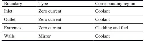
Moreover, the coefficients must be defined for each group of energy defined for the calculations. After material definitions, the appropriate boundary conditions are set matching the physical entities defined in the mesh. Table II shows the boundary conditions used for the simulation.
TABLE II
NEUTRONIC BOUNDARY CONDITIONS.
Boundary Type Corresponding region
Inlet Zero current Coolant
Outlet Zero current Coolant
Extremes Zero current Cladding and fuel
Walls Mirror Coolant
The calculations are started by a command call which builds the eigenvalue problem and solves the system. Fig. 3 shows a simple input file for milonga code. The material definitions are made in lines 10-16. The values can be constants like in the example below but can also be a function of a value or position. This feature of milonga
code makes coupling to external values straightforward.
Figure 3: A simple input file for milonga with line number counting.
D. Cross-sections
The beginning of life TRIGA IPR-R1 fuel composition was considered in this study.
In order to have a simulation with a real physical behaviour, it is fundamental to model the materials characteristics as close as possible to their physical aspects. This is achieved having a set of representative cross-sections of the materials neutronic behaviour.
[image:3.612.334.553.385.498.2]International Journal of Emerging Technology and Advanced Engineering
Website: www.ijetae.com (ISSN 2250-2459, ISO 9001:2008 Certified Journal, Volume 6, Issue 11, November 2016)
177
WIMS-D5 presents the macroscopic cross section homogenized in the cell and the value for each material. These macroscopic cross sections were used to feed
milonga.
As explained before, calculations are performed separating neutrons from the whole energy spectrum in two energy groups. All coefficients used by milonga to solve the equation diffusion were previously calculated [4,12]. Coefficients values are obtained for the materials listed in Tab. IV for the temperatures listed in Tab. III. WIMSD-5B processing gives cross-sections and diffusion coefficients for each material, with an exception for scattering cross-sections, which are given for a homogenized region formed by all materials. For this reason, scattering cross-sections are the same for all materials.
[image:4.612.44.292.459.591.2]These data are written in milonga format as constant values for each material and group.
TABLE III
TEMPERATURES FOR MATERIALS BASED ON VELOSO [7].
T1[K] T2[K] T3[K] T4[K]
Fuel 300 400 500 600
Cladding 300 396 403 410
Coolant 300 308.5 317 341
TABLE IV
MATERIALS COMPOSITION FOR CROSS-SECTIONS GENERATION WITH
WIMSD-5B[4,12]
Material Material
code Mass
Fuel
H (in zyrconium hydrade) 5001 3.7525e-02
Zr 91 3.7727e-02
U235 2235 2.5744e-04
U238 8238 1.0167e-03
Cladding Al 27 6.0261e-02
Coolant
H 3001 6.6653e-02
O 6016 3.3327e-02
E. Coupling Scheme
The coupling scheme is defined as a workflow, as depicted in Fig. 1, and is described below:
1. OpenFOAM is executed with a homogenous distribution of power for the fuel, which means that every control volume has the same value for power [W/m3];
2. The output of OpenFOAM is post-processed and the averaged temperature [K] for each material is applied to the temperatures reference table of cross-sections previously generated by WIMSD-5B and, using linear interpolation available by default in milonga, new sets of cross-sections are obtained for the set of temperatures.
3. The next step is to manually run milonga with this set of cross-sections to obtain neutron fluxes which are used to obtain the power distribution in the system.
4. The power distribution is then used as input in
OpenFOAM and a new temperature distribution is obtained.
5. The process is repeated until convergence. For this work, only one-step coupled calculation was performed.
In order to parse milonga’s power distribution output to OpenFOAM input format, a Python [11] script was written.
III. CALCULATIONS AND RESULTS
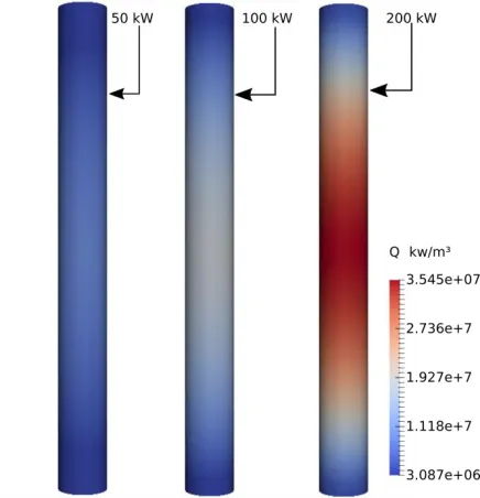
[image:4.612.319.567.482.560.2]Calculations were performed for three different powers, considering the equivalent of the TRIGA IPR-R1 reactor operating at 50 kW, 100 kW, and 200 kW, respectively 1.98 kW, 3.97 kW and 7.93 kW by pin. The first step of the workflow, consisting of running OpenFOAM with homogeneous power distributions gave the average temperatures shown in Tab. V.
TABLE V
AVERAGED TEMPERATURES [K] FOR MATERIALS AFTER FIRST STEP THERMAL-HYDRAULIC SIMULATIONS
Simulation power by pin
Material 1.98 [kW] 3.97 [kW] 7.93 [kW]
fuel 339.8 [K] 379.8 [K] 423.0 [K]
cladding 327.2 [K] 354.5 [K] 375.4 [K]
water/moderator 303.5 [K] 307.2 [K] 310.1 [K]
Temperatures from OpenFOAM simulations were used to generate the cross sections and fed back to milonga that calculated the neutron flux distribution. Fig. 4 shows the axial distribution of the neutron flux in the center of the fuel. It can be seen that the fluxes follow a physically expected sinusoidal shape distribution [11] for all simulated powers.
International Journal of Emerging Technology and Advanced Engineering
Website: www.ijetae.com (ISSN 2250-2459, ISO 9001:2008 Certified Journal, Volume 6, Issue 11, November 2016)
178
[image:5.612.342.546.115.343.2]The power distributions obtained from milonga and the temperatures along the axial center line of the fuel are shown in Fig. 5 and 6. As expected, the power profiles for all simulations have a sinusoidal like shape [11], since there are neutrons escaping from the top and bottom of the model. Temperature profiles have a non-symmetric shape due to the cold water entering the system. The water flow is heated when in contact with cladding, generating the non-symmetrical profile observed.
[image:5.612.60.277.241.472.2]Figure 4: Axial neutron flux distribution taken from the center line of the fuel.
Figure 5: Axial power profiles used by OpenFOAM from milonga.
Figure 6: Axial temperature profiles of the fuel calculated by
OpenFOAM with power distribution from milonga.
[image:5.612.334.552.414.640.2]The solid region power distribution corresponding to the fuel material is presented in Fig. 7 illustrating its relative variation among simulations.
Figure 7: Axial power profiles of fuel solid regions.
IV. CONCLUSIONS AND FUTURE WORK
[image:5.612.67.271.496.700.2]International Journal of Emerging Technology and Advanced Engineering
Website: www.ijetae.com (ISSN 2250-2459, ISO 9001:2008 Certified Journal, Volume 6, Issue 11, November 2016)
179
The coupled calculations show expected results for power profile when compared to former calculations [11]. The effectiveness of this methodology can be extended by the use of scripts to make the temperatures average process fully automatic and also using the script already wrote to process milonga output generating OpenFOAM input. Moreover, since both codes used for calculations are distributed with source-code, an iterative coupling scheme can be envisaged. The framework offered by milonga has built-in functions to read, write and process external files in different ways, making coupled calculation straightforward.
REFERENCES
[1] OpenFOAM, 2015, The Open Source CDF Toolbox: User guide. Version 3.0.1 [S.l.].
[2] Theler, G., 2014, On the design basis of a new core-level neutronic code written from scratch. The free nuclear reactor core analysis code. Mecánica Computacional Volume XXXIII, Number 48, Numerical Methods in Reactor Physics (B).
[3] Bennett, A., Avramova, M. and Ivanov, K., 2016, Coupled MCNP6/CTF code: Development, testing and application, Annals of Nuclear Energy, Volume 96, Pages 1-11, ISSN 0306-4549, http://dx.doi.org/10.1016/j.anucene.2016.05.008.
[4] Reis, P. A. L., Pereira, C., Costa, A. L., González-Mantecón, J., Veloso, M. A. F., Soares, H. V., 2015, Thermal Hydraulic and Neutron Kinetic Simulation of the TRIGA IPR-R1 Research Reactor using RELAP5-PARCS Coupled Model, Proceedings of European Research Reactor Conference, April 19-23, Bucharest, Romania.
[5] Geuzaine, C and Remacle, J.-F., 2009, Gmsh: a three-dimensional finite element mesh generator with built-in pre- and post-processing facilities. International Journal for Numerical Methods in Engineering 79(11), pp. 1309-1331.
[6] Launder, B. E. and Spalding, D. B., 1974, The numerical computation of turbulent flows, Computer Methods in Applied Mechanics and Engineering, Volume 3, Issue 2, 1974, Pages 269-289, ISSN 0045-7825, http://dx.doi.org/10.1016/0045-7825(74)90029-2.
[7] GNU General Public License, 2007, Version 3. Free Software Foundation. URL: http://www.gnu.org/licenses/gpl.html.
[8] Galassi, M., Davies, J., Theiler, J., Gough B., Jungman, G., Alken, P., Booth, M., Rossi, F. and Ulerich, R., 2009, GNU Scientific Library Reference Manual - Third Edition, ISBN 0954612078. [9] Trahan, T. J., 2014, An asymptotic, homogeneized, anisotropic,
multigroup diffusion approximation to the neutron transport equation. Thesis, Nuclear Engineering and Radiological Sciences, University of Michigan.
[10] Python Software Foundation. Python Language Reference, 2016, version 3.4. Available at http://www.python.org.
[11] Veloso, M. A., 2005, Avaliação Termo-hidráulica do Reator TRIGA IPR-R1 a 250 kW. NI-EC3-05/05, Belo Horizonte-MG, Brazil: Centro de Desenvolvimento da Tecnologia Nuclear (CDTN), Comissão Nacional de Energia Nuclear. (in Portuguese)
![TABLE V [K] FOR MATERIALS AFTER FIRST STEP](https://thumb-us.123doks.com/thumbv2/123dok_us/8689250.876730/4.612.319.567.482.560/table-v-k-materials-after-first-step.webp)