International Journal of Emerging Technology and Advanced Engineering
Website: www.ijetae.com (ISSN 2250-2459, ISO 9001:2008 Certified Journal, Volume 6, Issue 8, August 2016)
9
Development of Nozzles for Improving a Cleaning Performance
of Baghouse
Young-Ho Kum
1, Byung-Hyun Shon
2 1,2Department of Environmental Engineering, Hanseo University, Seosan-si, South Korea
Abstract - A lot of studies for venturi have been performed to improve the cleaning performance of filter bags. However, there are few studies for nozzles that directly spray cleaning air into the filter bag. The cleaning characteristics of blow tube and nozzles which are widely applied in the industries were identified by using the computational fluid dynamics (CFD) and compared each other. After confirming simulation results through a pilot scale experiment, we derived the optimal nozzle shape. In the pilot experiment, the cleaning performance depending on the changes of dust loading rate, cleaning frequency, and such things was evaluated and compared with the results of blow-tube in order to confirm the cleaning characteristics of 4 types of nozzles. In case of installing a nozzle into the blow tube, the cleaning efficiency increases because the cleaning air is concentrated onto the upper part to the end of the filter bag. Therefore, it can contribute to the reduction of the operation costs of a filter bag since the cleaning efficiency increases and the lifespan of a filter cloth is extended.
Keywords - cleaning nozzle, blow tube, pulse air jet, filter bag, computational fluid dynamics
I. INTRODUCTION
Baghouse is widely used to control particulate matters generated from industries. Because the baghouse is less affected by dust loading variations, easy to operate and control, and highly effective to collect fine particles when compared to the other precipitation methods. In addition, it reacts excellently to the allowable emission standard that continues to be strengthened. Recently, the filter bags that can be used even in high temperature as well as used for removal of fine particles are developing due to the advanced technology. So, the use of baghouse shows a continuously increasing trend [1, 2].
After dust collection, the filter bags should have cleaned periodically. Cleaning method of filter bags can be divided into 3 types such as shaker cleaned, reverse air cleaned, and pulse jet cleaned. Among the three methods, pulse jet cleaned type is widely used in the real field as it is not only excellent in cleaning performance but also simultaneously perform collection and cleaning. Pulse jet cleaned methods injects compressed air through the blow tube into filter bags to remove the dust cake attached on the filter bag.
Many variables should be considered in the design of cleaning parts of the baghouses. However, most of the installation contractors just depend on limited experience to design and operate the cleaning method [3, 4, 5].
This study is intended to develop a kind of nozzle for cleaning the filter bag. For this, we have simulated cleaning characteristics (cleaning air volume, velocity field, and velocity distribution of cleaning air flow, etc.) according to nozzle shapes using the CFD, and then designed nozzles. After confirming the simulation results and cleaning performance through a pilot scale experiment, we derived and suggested the optimal nozzle shape.
II. NUMERICAL ANALYSIS
In this study, we first analyzed the cleaning air flow characteristics of a blow-tube commonly used in current industries to develop a nozzle capable of increasing cleaning air volume under the same conditions. And, we have performed CFD analysis for various shapes of nozzles five times, and then compared it with the case that used a blow-tube only [6]. The final nozzle shapes selected through CFD analysis were 4 types as shown in [Table 1], and the performances of these 4 nozzle-shapes were analyzed [6].
International Journal of Emerging Technology and Advanced Engineering
Website: www.ijetae.com (ISSN 2250-2459, ISO 9001:2008 Certified Journal, Volume 6, Issue 8, August 2016)
10
Table 1
Design and photos for the four nozzle shape selected through the CFD analysis
Types Design Photo
Conventional system: Blow tube only (No nozzle)
-
Umbrella type nozzle (U type nozzle)
Skirt type nozzle (S type nozzle)
Double umbrella type
nozzle (DU type
nozzle)
Flanged double umbrella type
nozzle (FDU type
nozzle)
III. EXPERIMENTS
Fig. 1 shows the schematic diagram for the dust collecting and cleaning experiment. As shown in Fig. 1, the main parts are consisted of the dust feeding part, the cleaning one, the air inlet, the dust outlet, and the pressure gauge. Dust feeding system is a device to supply constant amount of dust into filter bag, and the dust injection was controlled at 10~100 g/min by regulating motor revolution.
The cleaning part consists of a compressor (UD-2525, United), a moisture condenser (SAD 402), an air flow rate controller, a blow tube, and a nozzle. The cleaning was
performed at the operation time of diaphragm valve 0.1∼
0.2 sec and pressure at pulsing 3 kgf/cm2. For the air intake
part, an I.D. fan (a single stage DBR-010) was used. And the dust exit part consists of a rotary valve (AD65, AUTOMA) and a dust storage tank. For monitoring the pressure drop, differential pressure gauge (Testo-510) and DPITs were used. The differential pressure between the inside and the outside of the filter bag was measured by installing a gauge on the front side of the I.D. fan and on the outer wall of the device at ±0.03 hPa of accuracy within
the 0∼100 hPa of gauge span. The filter bag was made of
[image:2.612.57.279.160.648.2]PE material in the size of ∅ 156 × H 2,000 mm [6].
Fig. 1. Schematic diagram for the experiment.
The experiment was carried out by dividing 3 cases
while using 3 kgf/cm2 of cleaning air pressure, 0.1 sec of
cleaning air injecting time, and 1.53 m3/min of fan capacity.
For the case of test-1, dust was injected at 40 g/min for 30 minutes and then it was cleaned in order to check the cleaning performance of each nozzle within a short period of time [6]. During the test-2, in order to experiment under the same conditions to those of the actual plant, dust was injected at 15 g/min for 5 minutes and then cleaned the filter bag. In the test-3, in order to experiment under the conditions similar to those of the actual industrial plant, dust was injected at 30 g/min and then cleaned at the very
time when the pressure drop reaches to 90 mmH2O. When
the pressure drops reached to 80 mmH2O after cleaning, it
was considered that the filter bag was on its last legs and the experiment was finished. The experimental conditions
are as shown in Table 2. The particle size distribution of
the dust used in this study are shown in Fig. 2, and the
[image:2.612.334.555.313.483.2]International Journal of Emerging Technology and Advanced Engineering
Website: www.ijetae.com (ISSN 2250-2459, ISO 9001:2008 Certified Journal, Volume 6, Issue 8, August 2016)
[image:3.612.48.288.154.440.2]11
Table 2
The experimental conditions
Variables test-1 test-2 test-3
Cleaning pressure 3 kgf/c㎡
Time of diaphragm valve 0.1 sec
Fan capacity 1.53 ㎥/min
Filter bag size 156 mm x 2,000 mm
Dust feeding rate 40 g/min 15 g/min 30 g/min
Distance between nozzle
and bag 30~130 mm 30 mm
Finishing pressure 100~130 mmH2O 80 mmH2O
Cleaning frequency 30 min 5 min Time to reach 90 mmH
[image:3.612.340.546.415.706.2]2O
Fig. 2. Particle size distribution of dust.
After finishing the experiment, differential pressure for each section was measured. In general, when cleaning with a blow tube, the dead zone that is poorly cleaned area exists at the inlet and the end of a filter-bag. So, we measured the pressure drop for each section when applying nozzles to the blow tube in order to check the change of dead zone. After finishing the test, we selected 7 points (point 1, 10 cm under the filter-bag’s inlet; point 2, 40 cm under the inlet; point 3, 70 cm under the inlet; point 4, 100 cm under the inlet; point 5, 130 cm under the inlet; point 6, 160 cm under the inlet; point 7 and 190 cm under the inlet) and measured the differential pressures. In addition, the lifespan of the filter-bag is shortened because the bag’s strength is decreased due to repetition of collection/cleaning cycles. Thus, we measures tensile strength of the filter-bag through KS K 0520 method after performing 1,800 cycles of collection/cleaning.
IV. RESULTS AND DISCUSSONS
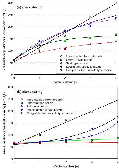
A. Comparison of Cleaning Performance with Nozzle Type (test-1)
In order to compare the cleaning performance of each nozzle within a short period of time, it was cleaned after operating it at 40 g/min of the dust for 30 minutes.
As can be seen in Fig. 3(a), it can be known that the trend of the pressure drop reaching to the filter bag is a straight line in case that only blow tube is installed. In case of the U type and FDU type nozzle, it shows the tendency that the pressure increase trends of them are similar to that of the only blow tube is installed in the first cycle, but it showed that those trends became stable gradually from the second cycle. However, in case of the S type nozzle, it showed that the pressure drop was higher than that of the blow tube until the second cycle, but it showed the similar trend to those of the U type and FDU type nozzle from the third cycle.
Fig. 3(b) shows the pressure drop that is put on the filter bag after cleaning. Unlike the pressure drop after dust collecting, it was found that the pressure increasing trend depending on each cycle was a straight line. In case that a blow tube is only installed, it can be seen that the cleaning did not almost done when it is compared to the pressure drop before cleaning. In case of the U type and FDU type nozzle, the cleaning performance was excellent since the pressure drop after cleaning increases slightly compared to the pressure before cleaning. In case of the DU and S type nozzle, it seems that the cleaning performance can be slightly improved.
Cycle number [n]
0 1 2 3 4
P
re
s
s
u
re
d
ro
p
a
ft
e
r
d
u
s
t
c
o
lle
c
ti
o
n
[
m
m
H2
O]
0 50 100 150 200 250 300
None nozzle : blow tube only Umbrella type nozzle Skirt type nozzle Double umbrella type nozzle Flanged double umbrella type nozzle (a) after collection
Cycle number [n]
0 1 2 3 4
P
re
s
s
u
re
d
ro
p
a
ft
e
r
d
u
s
t
c
le
a
n
in
g
[
m
m
H2
O]
0 50 100 150 200 250 300
None nozzle : blow tube only Umbrella type nozzle Skirt type nozzle Double umbrella type nozzle Flanged double umbrella type nozzle (b) after cleaning
International Journal of Emerging Technology and Advanced Engineering
Website: www.ijetae.com (ISSN 2250-2459, ISO 9001:2008 Certified Journal, Volume 6, Issue 8, August 2016)
12
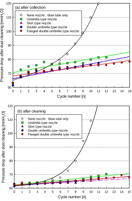
B. Comparison of Cleaning Performance with NozzleType (test-2)
As shown in Fig. 4(a), cleaning was successful up to the 5th cycle, but the pressure was rapidly increased from the 6th cycle when using only the blow tube. When using nozzles, the cleaning performance was excellent regardless of nozzle shapes. The slopes (pressure gradient with cycles) of nozzles were 0.63 in the U type, 0.82 in the S type, 0.78 in the DU type and 0.72 in the FDU type. Therefore, we can confirm that the FDU type nozzle steadily maintained low pressure drop, although the increasing rate of pressure drop was lower in the U type nozzle than the FDU type nozzle. Moreover, as shown in Fig. 4(b), the pressure drop increased sharply from the 7th cycle as the cycles progressed when applying the blow tube only. All of the
nozzles, however, showed more stable cleaning
performance than the blow tube only.
Cycle number [n]
0 1 2 3 4 5 6 7 8 9 10 11 12 13 14 15
P
re
s
s
u
re
d
ro
p
a
ft
e
r
d
u
s
t
c
le
a
n
in
g
[
m
m
H2
O]
60 70 80 90 100 110 120
None nozzle : blow tube only Umbrella type nozzle Skirt type nozzle Double umbrella type nozzle Flanged double umbrella type nozzle (a) after collection
Cycle number [n]
0 1 2 3 4 5 6 7 8 9 10 11 12 13 14 15
P
re
s
s
u
re
d
ro
p
a
ft
e
r
d
u
s
t
c
le
a
n
in
g
[
m
m
H2
O]
60 70 80 90 100 110 120
[image:4.612.62.277.335.663.2]None nozzle : blow tube only Umbrella type nozzle Skirt type nozzle Double umbrella type nozzle Flanged double umbrella type nozzle (b) after cleaning
Fig. 4. Comparison of the pressure drop change after dust collection and cleaning for each nozzle type at test-2.
C. Cycling Test (test-3)
This experiment was performed to test the continuous cycling operation under dust loading rate of 30 g/min.
When the pressure reaches 90 mmH2O a cleaning
process started and then collecting it again. If the pressure drop that is put onto the filter bag after cleaning reaches 80
mmH2O, it was judged that it was the time to replace the
filter cloth and the experiment was finished. Fig. 5 shows the result of collection/cleaning cycling test that compared the blow tube only and the blow tubes equipped with 4 types of nozzles.
As can be seen in Fig. 5(a), in case of using only the blow tube, the pressure increasing rate was 0.2273
mmH2O/min, and the total dust collecting and cleaning
cycles are 15 times, and the time that the lifespan of a filter
cloth is 69 minutes. And as shown in Fig. 5(b∼d), the
pressure increasing rate of U, S, and DU type nozzle were
0.1550, 0.1440, and 0.1153 mmH2O/min, respectively. In
case of installing the FDU type nozzle into the blow tube (Fig. 5(e)), the pressure increasing rate was 0.1143
mmH2O/min, the total dust collecting and cleaning cycles
were 17 times, and the lifespan of the filter cloth was 174 minutes, so the FDU type nozzle influences the improvement of the cleaning performance very much. As the results, that extends the replacement cycle of a filter cloth and improves the efficiency of the baghouse, so it is judged that it can contribute the reduction of the operation costs enormously.
Time [min.]
0 20 40 60 80 100 120 140 160 180
P
re
s
s
u
re
d
ro
p
[
m
m
H2
O]
60 70 80 90 100
Slope = 0.2273 mmH2O/min
69 min. (a) None nozzle : blow tube only
Time(min.)
0 20 40 60 80 100 120 140 160 180
P
re
ss
u
re
d
ro
p
(m
m
H2
O)
60 70 80 90 100
International Journal of Emerging Technology and Advanced Engineering
Website: www.ijetae.com (ISSN 2250-2459, ISO 9001:2008 Certified Journal, Volume 6, Issue 8, August 2016)
13
Time(min.)0 20 40 60 80 100 120 140 160 180
P
re
s
s
u
re
d
ro
p
(m
m
H2
O)
60 70 80 90 100
Slope = 0.1440 mmH2O/min 132 min. (c) Skirt type nozzle
Time(min.)
0 20 40 60 80 100 120 140 160 180
P
re
s
s
u
re
d
ro
p
(m
m
H2
O)
60 70 80 90 100
Slope = 0.1153 mmH2O/min 158 min. (d) Double umbrella type nozzle
Time [min.]
0 20 40 60 80 100 120 140 160 180
P
re
s
s
u
re
d
ro
p
[
m
m
H2
O]
60 70 80 90 100
[image:5.612.67.272.135.601.2]Slope = 0.1143 mmH2O/min 174 min. (e) Flanged double umbrella type nozzle
Fig. 5. Pressure drop in the filter bag with dust collection and cleaning cycles according to the four nozzle types.
Table 3 summarizes the cycling test results. As we can see in Table 3, the operation time has increased about twice when using the nozzles than the blow tube only. The operation time of collection and cleaning per 1 cycle was 9.9 min/cycle when applying the FDU type nozzle, which was 2.3 times higher than 4.3 min/cycle of using the blow tube only.
[image:5.612.345.544.574.716.2]Finally, we could confirm that all of the nozzle shapes applied to the blow tube increased the cleaning efficiency.
Table 3
Collection and cleaning characteristics for the four nozzle types
Blow tube only
U type nozzle
S type nozzle
DU type nozzle
FDU type nozzle
Operation time
(min) 64 123 120 144 169
Total removed
dust (g) 6440 12300 11950 14350 16900
Cleaning cycle
(times) 15 20 18 15 17
Operation
time/cycle 4.3 6.2 6.7 9.6 9.9
Pressure gradient (mmH2O/min)
0.2273 0.1550 0.1440 0.1153 0.1143
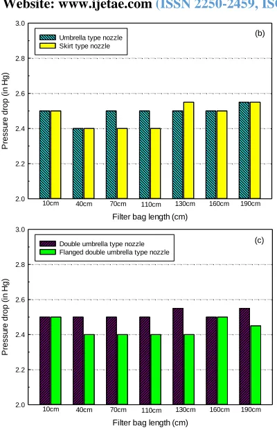
D. Pressure Drops for Each Position of Filter Bag
Fig. 6 shows the differential pressure for each position of the filter bag after finishing 15 cycles of collection and cleaning. The filter bag equipped with the blow tube only (Fig. 6(a)) represented higher pressure drops in all positions of the filter bag. This means that the cleaning air volume injected into the filter bag through the blow tube is small, and the cleaning air distribution is not uniform. Finally, we have confirmed that cleaning air flow of the blow tube was concentrated into the central part of the bag. As shown in
Fig. 6(b)~(c), almost cleaning efficiencies appeared to be
increased after applying nozzles to the blow tube. When equipped with the U type and S type nozzles, cleaning air was concentrated in the filter bag from the inlet to the center. The DU type nozzle showed mostly uniformed cleaning air flow in the filter bag from the inlet to the end. The FDU type nozzle is regarded as the most effective one in terms of concentrating the cleaning air up to the end of filter bag.
Filter bag length (cm)
10cm 40cm 70cm 100cm 130cm 160cm 190cm
P
re
ss
u
re
d
ro
p
(
in
H
g
)
2.0 2.2 2.4 2.6 2.8 3.0
International Journal of Emerging Technology and Advanced Engineering
Website: www.ijetae.com (ISSN 2250-2459, ISO 9001:2008 Certified Journal, Volume 6, Issue 8, August 2016)
14
Filter bag length (cm)P
re
ss
u
re
d
ro
p
(
in
H
g
)
2.0 2.2 2.4 2.6 2.8 3.0
Umbrella type nozzle Skirt type nozzle
10cm 40cm 70cm 110cm 130cm 160cm 190cm
(b)
10cm 40cm 70cm 110cm 130cm 160cm 190cm
Filter bag length (cm)
P
re
ss
u
re
d
ro
p
(
in
H
g
)
2.0 2.2 2.4 2.6 2.8 3.0
Double umbrella type nozzle Flanged double umbrella type nozzle
[image:6.612.70.270.121.431.2](c)
Fig. 6. Comparison of the pressure drop change according to the length of filter bag.
Filter bag
T
e
n
si
le
st
re
n
th
(
kg
f
/cm
2)
20 25 30 35 40
New filter bag Used filter bag (FDU type nozzle)
Used filter bag (U type nozzle)
Used filter bag (S type nozzle) 33.72
32.00 32.00 32.00
Fig. 7. Comparison of the tensile strength between new filter bag and used filter bag.
E. Tensile Strength
The lifespan of the filter bag is shortened because the bag’s strength is decreased due to repetition of collection and cleaning of dust.
Thus, tensile strength of the filter bag was measured after performing 1,800 cycles of collection and cleaning.
The tensile strength was 33.72 kgf/cm
2
in a new filter bag. The used filter bags cleaned by nozzles showed 32.00
kgf/cm2 of tensile strength, which was about 95% of the
new filter bag and expected not to significantly affect the
lifespan decline of the filter bag.
VI. CONCLUSION
The following conclusion was made.
1. When the FDU type nozzle was applied to the blow
tube, the secondary air could be easily flowed in the inside of the filter bag, and cleaning air was evenly injected into the filter bag from the inlet to the end.
2. We have confirmed an important factor that the
cleaning performance was improved when cleaning air was distributed evenly rather than concentrated in one part of the inside of the filter bag.
3. For the baghouse used in the actual plant, the venturi
was often set up on top of the bag in order to improve the cleaning performance. Therefore, further studies for using nozzles presented in this study and venturi used in the field at the same time are expected to decrease the operation costs in accordance with the filter bag lifespan and compressed air volume reduction.
Acknowledgement
This work (C0135672) was supported by Business for Cooperative R&D between Industry, Academy, and Research Institute funded Korea Small and Medium Business Administration in 2013.
REFERENCES
[1] Sung-Gil Hong, Yu-Jin Jung, Ki-Hyuk Lim, Jeong-Kun Yoo, and Byung-Hyun Shon, A Numerical Study on an Optimum Design of a Hybrid Collector Coupled with the Principle of Cyclone, Baffle and Bag-Filter, Journal of the Korea Academia-Industrial cooperation Society, Vol. 14, No. 2 pp. 983-989, 2013.
[2] Sung-Gil Hong, A study on development of high efficient multi-precipitator combined with the principle of cyclone, baffle and bag filter, Hanseo University, PhD thesis, 2013.
[3] Jung-Min Seo, Develpoment of pulse air jet bag filter cleaning assistant equipment, pp.1-10, 2004.
[4] Won-Hee Lee, Characteristics of electrostatic cyclone/bag filter with upper inlet, Pukyong National University, master thesis, 2000. [5] Byung-Hyun Park, Effect of jet nozzle on the reverse pulse jet
cleaning in bag-filter system, Kyung Hee University, master thesis, 2004.
[image:6.612.67.270.458.616.2]