International Journal of Emerging Technology and Advanced Engineering
Website: www.ijetae.com (ISSN 2250-2459,ISO 9001:2008 Certified Journal, Volume 4, Issue 6, June 2014)
252
A Generic Filtering Method for Removing Artefacts from Color
and Contrast Modifications of Digital Images
Usharani Ghattamaneni
1
Assistant Professor, MGIT, Hyderabad
Abstract—A generic Filtering method to remove artefacts from color and contrast modifications of digital images is presented. This work is concerned with the color and contrast modifications and compression of digital images. Contrast stretching, Gamma correction and histogram equalization or
specifications are example techniques to get those
modifications and standard JPEG, JPEG2000 are example compression techniques of digital images. A common drawback of most methods aiming at modifying the contrast or color content of images and compression of images is their strong tendency to create visual artefacts Such as attenuation of details and textures. In this paper, Adaptive Histogram equalization, jpeg compression and decompression techniques are applied on digital image which leads to some visual artefacts. Then Transportation map which is the difference between original image and transformed image is calculated, then a generic filtering method also called TMR filter which draws on the nonlocal Yaroslavsky filter is used to regularize the transportation map so that artefacts are suppressed . The performance of this method is evaluated through measures such as MSE, PSNR and Variance. Performance measures such as MSE, PSNR and Variance are calculated over Transformed image and TMR Filtered image and compared. The results are compared with related approaches such as mean, median and wiener filtering of transformed images and discussed..
Keywords— Color and contrast modifications, adaptive histogram equalization, JPEG encoding and decoding, Visual artefacts, Transportation map,TMR filter, artfacts-free image.
I. INTRODUCTION
The principal objective of image enhancement is to process a given image so that the result is more suitable than the original image for a specific application. The color and contrast modifications are elementary tools for image enhancement. Such changes may be obtained by applying a prescribed function to the gray values of images, as in contrast stretching or Gamma correction, or by prescribing the histogram of the resulting image, as in histogram equalization or specification. These techniques extend to color images by considering a luminance channel, as in Gamma correction, or by working on each color channel separately.
Image compression is minimizing the size in bytes of a graphics file without degrading the quality of the image to an unacceptable level. The reduction in file size allows more images to be stored in a given amount of disk or memory space. It also reduces the time required for images to be sent over the Internet or downloaded from Web pages. Image compression can be achieved by compression techniques such as GIF, PNG, JPEG and Progressive JPEG. The drawback of color and contrast modification techniques and compression techniques is to create visual artefacts such as noise enhancement, detail loss, texture washing, color proportion inconsistencies and compression artefacts. Several methods have been proposed in last few years to remove artefacts from color and contrast modification .The simplest one is proposed in [18] in the context of local histogram modifications and amounts to limit the modification depending on gradient values. While improving the results in some cases, this approach let most artefacts untouched. In [5], it is proposed to correct color transfer artefacts by using a variational regularization after the transfer. Still in a variational framework, the authors of [10] propose a unified formulation containing both color transfer and regularity constraints in a single energy minimization. For the problem of color proportion, a possible approach is to transfer color after having identified some homogeneous regions, as proposed in [6] and [19]. A related class of works takes interest in the avoidance of compression artefacts, usually using the properties of the compression scheme [20].
International Journal of Emerging Technology and Advanced Engineering
Website: www.ijetae.com (ISSN 2250-2459,ISO 9001:2008 Certified Journal, Volume 4, Issue 6, June 2014)
253 Finally TMR filter is applied on transformed images to remove visual artefacts. Performance measures such MSE, PSNR and Variance are calculated over transformed images and filtered images and compared those results separately for two transformed images. TMR filter gives better results compared to mean, median and wiener filters.
II. DESIGN METHODOLOGY
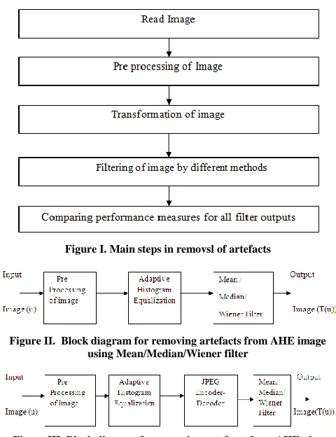
The input image is preprocessed that is color image is separated into three planes and size will be changed to 256x256 image. Adaptive histogram equalization method is used to change contrast of an input image. Adaptive Histogram Equalization method is an extension to traditional Histogram Equalization technique. It enhances the contrast of images by transforming the values in the intensity image. Unlike histogram equalization, it operates on small data regions (tiles), rather than the entire image. Each tile's contrast is enhanced, so that the histogram of the output region approximately matches the specified histogram. The neighboring tiles are then combined using bilinear interpolation in order to eliminate artificially induced boundaries. The contrast, especially in homogeneous areas, can be limited in order to avoid amplifying the noise which might be present in the image. The transformation of an image can be using AHE after preprocessing. The main steps of the methodology for removal of artefacts are shown in Fig I and include the following: read the input image, preprocessing of image, transformation of image, filtering of image by different methods, comparing performance measures for all filter outputs.
The block diagrams for removing artefacts from AHE image and AHE plus JPEG Encoding and Decoding image using mean filter are shown in Fig II and Fig III.In Fig II, the input image is preprocessed that is color image divided into three planes, and then Adaptive Histogram Equalization method is applied to change the contrast. Visual artefacts such as Noise enhancement, detail loss, color proportion inconsistencies are introduced. Mean filtering is applied to remove those artefacts and performance measures such as MSE, PSNR and Variance are calculated.In Fig III, the input image is preprocessed that is color image divided into three planes, then Adaptive Histogram Equalization method is applied to change the contrast and then JPEG Encoding& Decoding Technique is applied for compressing and decompressing. Visual artefacts such as Noise enhancement, detail loss, color proportion inconsistencies, compression aretfacts are introduced.
Mean filtering is applied to remove those artefacts and performance measures such as MSE, PSNR and Variance are calculated.
[image:2.612.324.564.172.484.2]Figure I. Main steps in removsl of artefacts
Figure II. Block diagram for removing artefacts from AHE image using Mean/Median/Wiener filter
Figure III. Block diagram for removing artefacts from AHE plus JPEG Encoding& Decoding image using Mean/Median/wiener filter
International Journal of Emerging Technology and Advanced Engineering
Website: www.ijetae.com (ISSN 2250-2459,ISO 9001:2008 Certified Journal, Volume 4, Issue 6, June 2014)
[image:3.612.50.290.177.252.2]254 TMR filtering is applied to remove those artefacts and performance measures such as MSE, PSNR and Variance are calculated.
Figure IV. Block diagram for removing artefacts from AHE image using TMR filter
FIgure V: Block diagram for removing artefacts from AHE plus JPEG Encoding& Decoding image using TMR filter
III. TMR FILTER
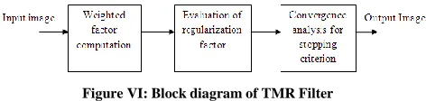
[image:3.612.49.289.178.352.2]The block diagram for TMR Filter is shown in Fig VI. The transportation map M (u) which is the difference between transformed image and original image is applied to TMR Filter. In this, weighted factor is computed, Regularization term is evaluated, finally stopping criterion is found out regularization process convergence. Then enhanced image will be obtained by combining the regularized image with original image (u).
Figure VI: Block diagram of TMR Filter
All the artefacts mentioned above are removed by regularizing the transportation map, which is defined as the image of the differences between the original image and the one after contrast or color modification. All these artefacts may be interpreted as spatial irregularities of this transportation map. In order to regularize this map without introducing blur in the final image, inspiration is taken from nonlocal methods that have been proposed for image denoising and more precisely from the Yaroslavsky filter.
The transportation map is filtered by averaging pixel values using weights that are computed on the original image, therefore adapting to the geometry of this initial image. It will be shown that artefacts are progressively suppressed by iterating this filtering stage.
T(u) is the image after color or contrast modification. In what follows, we write M(u):=T(u) - u for the transportation map of image . We propose to regularize it thanks to the operator Yu , a weighted average with weights
depending on the similarity of pixels in the original image . The effect of this operator on an image v:Ω→ Rn with n ≥ 1
which is defined as
With weights
We calculate the transportation map which gives the difference between orginal image and transformed one. Yu
is the operator ,a weighted average with weights depending on the similarity of pixels in the original image u. We calculate the weights for each and every pixel leaving the first pixel; we start from second pixel .we take 8 neighbor hoods of each pixel. Where ||.|| stands for the Euclidean distance in Rn, where,N(x) = x + N(0) ⊂ Ω with N(0) a spatial neighborhood of 0, where σ is a tuning parameter C(x) of the method and is the normalization constant.
We will add all the weights which are calculated for each and every pixels. Observe that if we apply to the image u , we obtain the Yaroslavsky filter. If the weights also decrease as a function of the distance to x,Yu, becomes
similar to the cross bilateral filter introduced in [19] for flash photographic enhancement.The regularization of the image T(u), referred to as transportation map regularization (TMR), is then defined as TMRu(T(u)) : = u + YuM(u).
Now, observe that this formulation can be divided in two
terms as of image TMRu(T(u)) = Yu(T(u)) + u - Yu(u)
First, the image T(u)is filtered by a nonlocal operator Yu,
following the regularity of the image . This operation attenuates noise, compression, and color proportion artefacts but also the details of the image T(u). The second operation performed by the TMR filter consists in adding the quantity udetails =: u – Yu(u) , which can be considered as
[image:3.612.53.289.525.581.2]International Journal of Emerging Technology and Advanced Engineering
Website: www.ijetae.com (ISSN 2250-2459,ISO 9001:2008 Certified Journal, Volume 4, Issue 6, June 2014)
255 The previously defined filter has several nice properties which enable us to reduce the visual artefacts. First, observe that this filter leaves all the images , u + λ, λ Є Rn
, unchanged. Moreover, if the application consists of a
multiplication by a positive constant α , then α) . TMRu(αu) = αu + (1 – α)
If α > 1, the transfer increases the contrast. In that case, the TMR filter reduces the noise contained in the image difference . If α > 1 the transfer decreases the contrast and the TMR filter restores the lost details contained in . Finally, another interesting aspect of the TMR filter is that the discrete distribution of the regularized image TMRu(T(u).This property somewhat prevents the creation
of false colors which may be caused by the regularization process. In practice, more than one iteration of the TMR filter is required to remove all the aforementioned artefacts. The image T(u) after k iterations of the TMR filter can be
written as follows
There refers to the recursive use of the Yu filter. The
question is then how to choose the right number of iterations k and one may wonder what happens for large values of . Studying the limit of when k → ∞boils down to the study of the limit of the powers of a matrix. Indeed, let us resize the discrete image into a column vector v of size m. In this setting, the linear filter Yu can be
written as an matrix , whose coefficients are
, 1 ≤ i,j ≤ m.
In this formulation, I is the index in the vector v of a pixel x in u , and N(i) is the set of indexes in corresponding to the 2-D neighborhood N(x) in . If we resize the map into the vector w , then
corresponds to the vector Akw . Now, observe that the matrix A is stochastic, i.e., that. and If ,we assume that A is primitive, i.e., that is strictly positive for some r Є N* and
this is clearly true if the neighborhoods N(x) are disks of radius ρ > 1 in , the Perron–Frobenius theorem permits to conclude that Ak tends toward a stochastic matrix A∞ when k → +∞, and that all of the lines of A∞ are equal This
means that the map tends toward a constant image In other words, the limit image
is only a shift of the image u by a constant color. The Perron–Frobenius theorem also gives information on the convergence rate Ar of towards
.
More precisely, we know that behaves as, where λ is the Eigen value of A with the second largest modulus and where m(λ)is the algebraic multiplicity of λ. In practice ||λ||, is generally close to 1 for a similarity matrix A , and the resulting convergence rate is quite slow, as it will be confirmed in the experimental section. The aim of the next section is to propose a way to stop automatically the iterations of the filter TMR.In order to control the iterations of the TMR filter, we compute at each iteration a convergence map, written and defined at each pixel as follows
Where ||.|| is the average Euclidean norm in Rns . We then consider that there is numerical convergence in pixel x when ,C(x) < t and the TMR filter is only applied to pixels for which the convergence map is greater than the threshold t. In all experiments, the convergence threshold has been set equal to t = 1 (for n* 8 -bit images). In practice, if x is the first pixel to attain this numerical convergence, this boils down to replace the line corresponding to x in matrix A by the same line in the identity matrix. The new matrix is A1 then iterated until a second pixel attains numerical
convergence, and is then replaced by A2 , etc. Observe that
each matrix Aj is stochastic and such that converges
when k → +∞ (see Appendix C for a proof), which implies that a new pixel attains numerical convergence after a finite number kj of iterations. The whole process hence stops
once all pixels satisfy C(x) < t. At the end, if is the vector
corresponding to , we get
Observe that the proposed stopping criterion permits also to save computation time since the iterations of the TMR filter concern fewer and fewer pixels.
IV. RESULTS & DESCUSSIONS
International Journal of Emerging Technology and Advanced Engineering
Website: www.ijetae.com (ISSN 2250-2459,ISO 9001:2008 Certified Journal, Volume 4, Issue 6, June 2014)
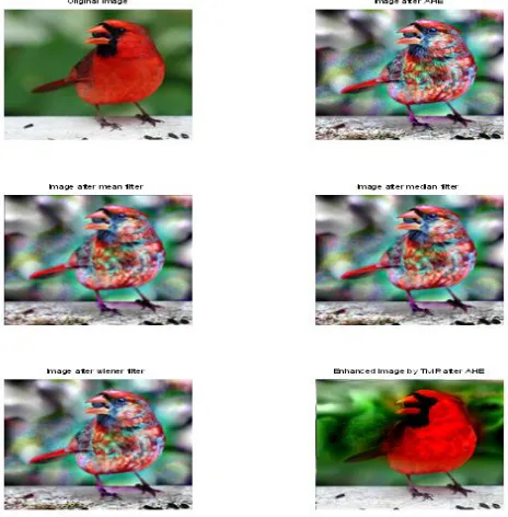
256 The Fig VIII(f) has less artefacts and much similar to original figure as the mean square error for transformed image-II after applying TMR filter is less and the PSNR of transformed image-II after applying TMR filter is more compared to the same after applying another filters such as mean, median, wiener filters .we can say TMR filter is giving better results compared to mean,median and wiener filters for transformed image-II.
Figure VII:a) Original image b) Image after AHE(Transformed image-I) c) Image after mean filter d) Image after median filter e)
[image:5.612.328.565.115.386.2]Image after wiener filter f) Image after TMR filter
Figure VII: a) Original image b) Image after AHE plus JPEG(Transformed image-II) c) Image after mean filter d) Image after median filter e) Image after wiener filter f) Image after TMR
filter
[image:5.612.58.290.234.470.2]V. CONCLUSIONS
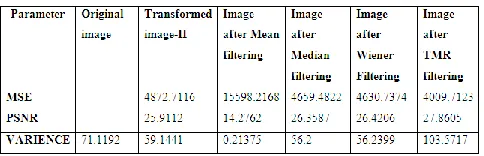
Table I
International Journal of Emerging Technology and Advanced Engineering
Website: www.ijetae.com (ISSN 2250-2459,ISO 9001:2008 Certified Journal, Volume 4, Issue 6, June 2014)
[image:6.612.51.293.160.238.2]257
Table 2
Comparison of Performance Measures for Transformed Image-II
In this paper a generic filtering procedure is used in order to remove the different kinds of artefacts created by radiometric or color modifications. The ability of the proposed TMR filter to deal with these artefacts while restoring the fine details of images has been demonstrated on various examples. This approach can be used as a post processing for many classical image modification tasks, such as contrast and color transfer, movie restoration, gamut mapping, or high-dynamic-range (HDR) image visualization. In this work, a generic filtering method is proposed to suppress artifacts while preserving details. In this initially, a radiometric transformation is applied to a digital image & Transportation map which is the difference between original image and radio metrically transformed image is obtained .Then the transportation map is regularized using a generic filter called TMR filter to remove the artefacts from color contrast modified images. The proposed method draws on the nonlocal Yaroslavsky filter to regularize the transportation map.The transportation map is filtered by averaging pixel values using weights that are computed on the original image, therefore adapting to the geometry of this initial image. It will be shown that artefacts are progressively suppressed by iterating this filtering stage. The efficiency of the method can be shown on various radiometric modifications: contrast equalization, JPEG Encoding & Decoding. The visual artefacts can be minimized by using TMR filter compared to mean, median and wiener filter and it gives better results.
MSE of transformed image-I after TMR filter is reduced by 963dB.It is less compared to mean, median and wiener filter outputs. PSNR of transformed image-I after TMR filter is improved by 2dB.It is high compared to mean, median and wiener filters. Variance of Transformed image-I after TMR filter is 102.
MSE of transformed image-II after TMR filter is reduced by 863dB.It is less compared to mean, median and wiener filter outputs. PSNR of transformed image-II after TMR filter is improved by 2dB.It is high compared to mean, median and wiener filters. Variance of Transformed image-II after TMR filter is 103.
REFERENCES
[1] A. C. Bovik, Handbook of Image and Video Processing (Communications,Networking and Multimedia). Orlando, FL: Academic, 2005.
[2] C. Villani, Topics in Optimal Transportation. Providence, RI: Amer.Math. Soc., 2003.
[3] E. Reinhard, M. Ashikhmin, B. Gooch, and P. Shirley, ―Color transferbetween images,‖ IEEE Comput. Graph. Appl., vol. 21, no. 5, pp.34–41, 2001.
[4] J. Morovic and P. Sun, ―Accurate 3D image colour histogram transformation,‖Pattern Recognit. Lett., vol. 24, no. 11, pp. 1725– 1735, Jul.2003.
[5] F. Pitié, A. C. Kokaram, and R. Dahyot, ―Automated colour grading using colour distribution transfer,‖ Comput. Vis. Image Underst., vol. 107, pp. 123–137, Jul. 2007.
[6] Y.-W. Tai, J. Jia, and C.-K. Tang, ―Local color transfer via probabilistic segmentation by expectation-maximization,‖ in Proc. IEEE Comput. Soc. Conf. Comput. Vis. Pattern Recognit., 2005, pp. 747–754.
[7] R. H. Selzer, ―The use of computers to improve biomedical image quality,‖ in Proc. AFIPS, 1968, pp. 817–834.
[8] A. Rosenfeld and E. Troy, ―Visual texture analysis,‖ in Proc. UMRKellyComm. Conf., 1970, p. Sect. 10–1.
[9] J. Delon, ―Midway image equalization,‖ J. Math. Imaging Vis., vol. 21,no. 2, pp. 119–134, Sep. 2004.
[10] N. Papadakis, E. Provenzi, and V. Caselles, ―A variational model for histogram transfer of color images,‖ IEEE Trans. Image Process., vol.19, no. 11, p. , Nov. 2010.
[11] J. Delon, ―Movie and video scale-time equalization application to flicker reduction,‖ IEEE Trans. Image Process., vol. 15, no. 1, pp. 241–248, Jan. 2006.
[12] J. Delon and A. Desolneux, ―Stabilization of flicker-like effects in image sequences through local contrast correction,‖ SIAM J. Imaging Sci., vol. 3, no. 4, pp. 703–704, Oct. 2010.
[13] G. Haro, M. Bertalmío, and V. Caselles, ―Visual acuity in day for night,‖ Int. J. Comput. Vis., vol. 69, no. 1, pp. 109–117, 2006. [14] M. Bertalmío, V. Caselles, E. Provenzi, and A. Rizzi, ―Perceptual
color correction through variational techniques,‖ IEEE Trans. Image Process., vol. 16, no. 4, pp. 1058–1072, Apr. 2007.
[15] S. G. Narasimhan and S. K. Nayar, ―Vision and the atmosphere,‖ Int. J. Comput. Vis., vol. 48, no. 3, pp. 233–254, 2002.
[16] L. A. Torres-Méndez and G. Dudek, ―Color correction of underwater images for aquatic robot inspection,‖ in Proc. Energy Minimiz. Methods Comput. Vis. Pattern Recognit., 2005, pp. 60–73. [17] U. Lipowezky, ―Grayscale aerial and space image colorization using
texture classification,‖ Pattern Recognit. Lett., vol. 27, no. 4, pp. 275–286, 2006.
[18] S. M. Pizer, E. P. Amburn, J. D. Austin, R. Cromartie, A. Geselowitz, T. Greer, B. T.H. Romeny, and J. B. Zimmerman, ―Adaptive histogram equalization and its variations,‖ Comput. Vis. Graph. Image Process., vol. 39, no. 3, pp. 355–368, 1987.
[19] A. Abadpour and S. Kasaei, ―An efficient PCA-based color transfer method,‖ J. Vis. Commun. Image Represent., vol. 18, no. 1, pp. 15– 34, 2007.