-=-
-
:;-~-;;
-
- - -
--
-
- -
--
--
-
- - - -
--
-
-
_
...
---
--
---
_.-
Maintenance Library
Control Unit
Models 1A, 18, 1C, 10, 21A, 218, 21C, 210, 31A, 31C and31D
. .Preface
This manual contains the information needed by the sup-port Field Engineering (FE) Customer Engineer to maintain the 3274 Control Unit Models 1A, 18, 1C, 10, 21A,21B, 21C, 210, 31A, 31C and 31 D.
Note: For purposes of brevity and clarity, the one- and
two-digit numbers associated with the 3274 Models A, 8,
C, and D. units are not used in this manual. All unit
desig-nations are abbreviated by model type only~ such as: 3274
Model A, 3274 Model 8,3274 Model C and 3274 Model D.
The maintenance procedures described in this manual and performed by the Support Customer Engineer represent a part of the overall support structure for the 3274 Control Unit. This support structure begins at the 3274 operator level and is briefly described as follows:
• 3274 Operator - Performsinitial problem isolation and recording of 3274 status indications by following the procedure in the 3274 Problem Determination Guide,
GA27-2854. If the problem involves other than a cus-tomer operating procedure or cuscus-tomer-supplied power,
the operator completes the 3274 Problem Report Form
and requests IBM service.
Fourth Edition (March 1981)
This is amajor revision of, and obsoletes. SY27-2512-2. The draw-ings and specifications contained herein shall not be reproduced in whole or in part without written permission.
IBM has prepared this maintenance manual for the use of IBMcus-tomer engineers in· the installation, maintenance, or repair of the specific machines indicated. IBM makes no representations that it is suitable for any other purpose.
It is possible that this material may contain reference to, or informa-tion about, I BM products (machines and programs), programming, or services that are not announced in your country. Such references or information must not be construed to mean that IBM intends to announce such IBM products, programming, or services in your country.
Requests for IBM publications should be made to your IBM repre-sentative or to the I BM branch office serving your locality.
©Copyright International Business Machines Corporation 1978, 1979,1980,1981
SY27-2512-3
• Product Customer Engineer - Performs the maintenance
procedures described in this manual to Isolate the prob-lem to a field replaceable unit (FRU). The 3274
Prob-lem Report Form prepared by the operator gives the
3274 indications necessary for performing these proce-dures. If the problem cannot be isolated and corrected, the Product Customer Engineer requests assistance from the next level of the support structure.
• Support Customer Engineer - Verifies the results
obtained by the Product Customer Engineer and thor-oughly analyzes the problem by means of the following:
• Tests
• Log Information
• Error Code Definitions
• Result of Host Test Routines
• Special Tools and Test Equipment
If the problem cannot be isolated and resolved using these service aids, the Support Customer Engineer records the problem indications and supporting information on the 3274 Problem Checklist and requests assistance from the next level of the support structure.
A form for readers' comments is provided at the back of this publi-cation. If the form has been removed, address comments to IBM Corporation, Department 52Q, Neighborhood Road, Kingston, N. Y. 12401. I BM may use or distribute any of the information you supply in any way it believes appropriate without incurring any obligation whatever. You may, of course, continue to use the information you supply.
Organization
This manual is organized as follows:
• Chapter 1 - Maintenance Approach and System Overview
• Chapter 2 - Subsystem Indicators, Symbols, and Messages
• Chapter 3 - Subsystem Error Logs and Test Formats
• Chapter 4 - Subsystem Tests, External Tests, and Sub-system Service Aids
• Chapter 5 - Reference Data
• Chapter 6 - Tools and Test Equipment
• Appendix A - Support Structure Information Form
• Appendix B - Models A, B, C, and D Error Codes
• Appendix C - Structured Field and Attribute Processing (SFAP) Data Stream Error Extensions
• Appendix D - Abbreviations
Federal Communications Commission (FCC) Statement
Warning: This equipment generates, uses, and can radiate radio frequency- energy and, if not installed and used in accordance with the instructions manual, may cause inter-ference to radio communications. It has been tested and found to comply with the rimits for a Class A computing device pursuant to Subpart
J
of Part 15 of FCC Rules, Which are designed to provide r.easonable protection against such interference when operated in a commercial environ-ment. Operation of this equipment in a residential area is likely to cause interference, in which case the user at his own expense will be required to take whatever measures may be 'required to correct the interference.This warning is also applicable to all attaching units pro-duced for use in the USA that have been manufactu"red after December 31, 1980. A notice of compliance has been affixed within the customer access area of all affected units.
Contents
Chapter 1. Maintenance Approach and System Overview 1-1 1.1 Maintenance Approach 1-1
1.2 Subsystem Data Flow 1-2 1.2.1 IML Test Data Path 1-2 1.2.2 IML of Unit Code 1-2
1.2.3 Message Data Flow between 3274 Control Unit and Attached Devices 1-3
1.2.4 1.2.5 1.3 1.3.1 1.3.2 1.3.3 1.3.4 \ 1.3.5 1.3.6 1.3.7 1.3.8 1.3.9 1.4
Message Data Flow between 3274 Control Unit and Host System 1-3
Status, Error, and Log Data Flow 1-4 . Subsystem Functions 1-5
Control Unit Power-On Reset 1-6 Keystroke Handling 1-6 Sending to Host 1-8 Receiving from Host 1-8 Error Handling and Logging 1-8 Internal Testing 1-8
Function Priority 1-8 Local Channel Data Flow 1-9 Type A Adapter Coax Data Path 1-10 Supporting Publications 1-10
Chapter 2. Subsystem Indicators, Symbols, and Messages 2-1 2.1 Introduction 2-1
2.2 842 1 Indicators 2-1 2.3 DC ON Indicator 2-1
2.4 ONLINE/OFFLINE Indicator and Switch for Models A,
2.4.1 2.4.2 2.5 2.5.1 2.5.2 2.5.3 2.5.4 2.5.5 2.5.6 2.5.7 2.5.8
B, and D 2-2 Model A 2-2 Models Band D 2-2
Operator Information Area Layout 2-3 Readiness and System Connection Symbols 2-3 Do Not Enter (Input Inhibited) Symbols 2-4 Communication Reminder Symbol 2-5 Shifts and Modes Symbols 2-5 Printer Status Messages 2-5 Machine Check Numbers 2-5 Program Check Numbers 2-5 Communication Check Numbers 2-5
Chapter 3. Subsystem Error Logs and Test Formats 3-1 3.1 Introduction 3-1
3.2 Test 0: Communication Path Test and 3278 Display Test 3-1
3.2.1 3.2.2 3.3 3.3.1. 3.3.2 3.3.3 3.3.4 3.3.5 3.3.6 3.3.6.1 3.3.6.2 3.3.7 3.3.8 3.3.9 3.3.10 3.4
Description 3-1
Procedure for Requesting Test 0 3-1 Test 1: OveiView 3-1
Test 1 Device Logs 3-2 Test 1 Host Adapter Logs 3-2
Test 1 Common Communications Adapter (CCA) Log for BSC 3-3
Test 1 Common Communications Adapter (CCA) Log and High-Performance Communications Adapter (HPCA) Log for SDLC 3-6
Test 1 Local Channel Attachment (Model A) Log 3-9 Test 1 Local Host Attachment (Models B and D) 3-10 Model B 3-10
Model D 3-10
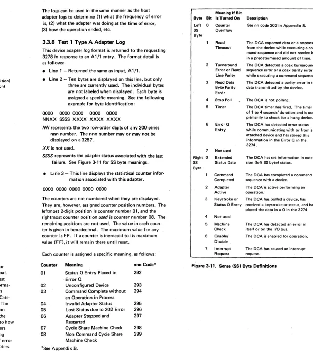
Test 1 Device Adapter Logs 3-11 Test 1 Type A Adapter Log 3-11 Test 1 Type B Adapter Log 3-12 Control Logic Error Log 3-12
Test 2: Display Configuration Information 3-12
3.5 3.6 3.7 3.7.1 3.7.2 3.8 3.9 3.10 3.10.1 3.10.2
Test 3: Display the Status of All Configured Terminals and Display the Control Unit Summary Counters 3-13 Test 4: Reset Any Test 1 Log 3-14
Test 6: Device Control Block Display 3-14 Test 6 Byte Identification 3-14
DCB Bit Definitions 3-15
Test 7: Dynamic Convergence (Color) 3-16 Test 8: PS, Highlighting, and Color 3-16 3277 Path Test and Test Request Key 3-16 BSC or Local Host Attached 3-16 SNA Attached 3-16
Chapter 4. Subsystem Tests, External Tests, and Subsystem Service Aids 4-1
4.1 4.2 4.2.1 4.2.2 4.2.3 4.2.4 4.2.5 4.2.6 4.2.7 4.3 4.3.1 4.3.2 4.3.3 4.3.4 4.3.5 4.4 4.4.1 4.4.2 4.4.3 4.4.4 4.4.5 4.5 4.5.1 4.5.2 4.5.3 4.6 4.6.1 4.6.2 4.6.3 4.6.4 4.6.5 4.6.6 4.6.7 4.6.8 4.6.8.1 4.6.8.2 4.6.8.3 4.6.9 4.6.9.1 4.6.9.2
Introduction 4-1
Initial Machine Load (lML) Tests 4-1 ALT 1 IML Mode 4-1
ALT 2 IML Mode, Model C with Wrappable Modem (Test/Operate Switch in Operate Position) 4-1 ALT 2 IML Mode, Model C without Wrappable Modem (Test/Operate Switch in Test Position) 4-1
ALT 2 IML Mode, Model A Local Channel Attachment 4-2
ALT 2 IML Mode, Model B Local Host Attachment 4-2 ALT 2 IML Mode, Model D Local Host Attachment 4-2 ALT 2 IML Mode, Modem Self-Test for Model C with Greater than 1200-bps Integrated Modem 4-2 Local Model A Display System Online Tests (T3274B) 4-2
Purpose 4-2
Applicable Executive Control Programs 4-2 Composite Error Message Description 4-3 OLT Routines 4-3
CDS Card Format, Model A 4-3
Local Models Band D Display System Online 4-3 Purpose 4-3
Applicable Executive Control Programs 4-3 Composite Error Message Description 4-4 OLT Routines 4-4
CDS Card Format, Models Band D 4-4 Model. C Display System Online Tests 4-4 Purpose 4-4
Applicable Executive Control Programs 4-4 Model C Online Tests 4-4
Serviceability Aids 4-5
Monitoring of EIA Interface Lines (Model C) 4-5 Monitoring of Bus/Tag Interface Lines (Models A, B, and
D) 4-5
Isolate Feature Board 01A-A2 4-5 Diskette Patching Procedure 4-5 Dump Procedure 4-6
BackupSystem Diskette Generation 4-6 Display Customizing Responses 4-.6 Coax Cables (hand I) 4-6
Cable h (Indoor) 4-6 Cable I (Outdoor) 4-6 Coax Cable Splicing 4·6 Coax Testing with Scope 4-6 Testing for Discontinuities 4-7 Setup and Test Procedures 4-7
Chapter S. Reference Data 5-1 5.1 Introduction 5-1
5.2 Control Unit Command Summary 5-1 5.2.1 Write 5-1
5.2.2 Erase/Write 5-1
5.2.3 Erase/Write Alternate 5-1 5.2.4. Erase All Unprotected 5-1 5.2.5 Read Buffer 5-1
5.2.6 Read Modified 5-1 5.2.6.1 Read Modified Read 5-1 5.2.6.2 Short Read Read 5-1
5.2.6.3 Test Request Read [Models B, C (BSC), and D) 5-1 5.2.7 Read Modified All (SNA Only) 5-1
5.2.8 No Operation (Models B and D Only) 5-1 5.2.9 Select (Models Band D Only) 5-1 5.2.10 Sense (Models Band D Only) 5-1 5.2.11 Copy [Model C (BSC») 5-1 5.3 Control Unit Order Summary 5-1 5.3.1 Set Buffer Address (SBA) 5-1 5.3.2 Start Field (SF) 5-1
5.3.3 Insert Cursor (IC) 5-1 5.3.4 Repeat to Address (RA) 5-2
5.3.5 Erase Unprotected to Address (EUA) 5-2 5.3.6 Program Tab (PT) 5-2
5.3.7 NewLine (NL) 5-2 5.3.8 End of Message (EM) 5-2 5.3.9 Duplicate (DUP) 5-2 5.3.10 Field Mark (FM) 5-2
5.3.11 Forms Feed (FF) (3262,3287,3288, and 3289 Printers) 5-2
5.3.12 Suppress Index (SI) (3288) 5-2
5.3.13 Carriage Return (CR) (3262,3287 with 3274/3276 5.4 5.4.1 5.4.2 5.5 5.6 5.6.1 5.6.2 5.7 5.8 5.8.1 5.8.2 5.9 5.9.1 5.9.1.1 5.9.1.2 5.9.1.3 5.9.1.4 5.9.1.5 5.9.1.6 5.9.1.7 5.9.1.8 5.9.1.9 5.9.1.10 5.9.1.11 5.9.1.12 5.9.2
Attachment, and 3289 Printers) 5-2 I/O Interface Codes 5-2
Examining 3278 Attributes and Modified Data Tags 5-6 Examining 3279 Attributes and Modified Data Tags 5-6 Sequence/Response Diagrams, Models A, B, and D 5-8 Status and Sense Byte Dermitions 5-9
Description 5-9
Error Recovery Procedures 5-12
Sequence/Reponse Diagrams, Model C, BSC 5-13 Remote Status and Sense Byte Definitions, Model C, BSC 5-18
Error Recovery Procedures, Model C, BSC Supplementary Procedures 5-21 Model A, Local Attachment (SNA Version) Commands 5-21
Write Command 5-21 Read Command 5-21 No Operation Command 5-21 Sense Command 5-21 Control Command 5-21 Write Break Command 5-22 Write Start 0 Command 5-22 Read Start 0 Command 5-22 Write Start 1 Command 5-22 Read Start 1 Command 5-22 Restart Reset Command 5-22 Sense ID Command 5-22 Status and Sense Definitions 5-22
5-20
5-21
59.2.1 5.9.2.2 5.9.3 5.9.3.1 ' 5.9.3.2 5.10 5.10.1 5.10.1.1 5.10.1.2 5.10.2 5.10.2.1 5.10.2.2 5.10.3 5.11 5.11.1 5.11.2 5.11.3 5.11.4 5.11.5 5.11.6 5.12 5.12.1 5.12.2 5.12.3 5.12.4 5.12.5
Status Bits 5-22 Sense Bits 5-23
Error Recovery Procedures 5-24 Model-A-Detected Errors 5-24 Channel-Detected Errors 5-24
SDLC Sequence/Response Descriptions 5-24 SDLC Transmission Frames 5-24
Response Modes 5-24 Control Field 5-24
Sequence Error Recovery Procedures 5-25 Abort Function 5-25
Timeout Controls 5-25
Hexadecimal Notation and Frame Summary 5-25 SNA Information 5-25
Session Control 5 -25 Data Flow Control 5-25 Transmission Header 5-26 Request/Response Header 5-26 SNA Definitions 5-27
SDLC/SNA Command to Start a Session 5-27 SDLC/SNA Error Information 5-28
Exception Response with Sense Data Included 5-28 SNA Sense Codes 5-28
Logical Unit Status (LUSTAT) 5-29 Command Reject 5-30
Request Maintenance Statistics (REQMS) Command 5-30
5.12.5.1 Record Formatted Maintenance Statistics (RECFMS) 5-30
5.12.5.2 RECFMS Formats 5-31 5.13 Switches and Controls 5-31
5.14 BSC and SNA Readiness Symbols 5-32 5.15 Digital Data Service (DDS) Adapter 5-34
Chapter 6. Tools and Test Equipment 6-1 6.1 Introduction 6-1
6.2 Buffered Teleprocessing Diagnostic {\.nalyzer and Tester 6-1
6.3 NU Data Tester 6-1 6.4 Maintenance Device 6-1
6.5 PT-2 Attachment to Non-EIA Interfaces 6-1
Appendix A. Support Structure Information Form A-I Appendix B. Models A, B, C, and D Error Codes B-1 Appendix C. Structured Field and Attribute Processing (SF AP)
Data Stream Error Extensions C-l Appendix D. Abbreviations D-1
Figures
Figure 1-1.
Figure 1-2. Figure 1-3. Figure 1-4. Figure 1-5.
Figure 1-6. Figure 1-7. Figure 1-8. Figure 1-9. Figure 1-10. Figure 1-11. Figure 1-12. Figure 1-13. Figure 2-l. Figure 2-2. Figure 2-3.
Figure 2-4. Figure 2-5.
Figure 2-6. Figure 2-7. Figure 2-8. Figure 2-9. Figure 3-1.
Figure 3-2. Figure 3-3.
Figure 3-4.
Figure 3-5. Figure 3-6.
Figure 3-7. Figure 3-8. Figure 3-9. Figure 3-10. Figure 3-11. Figure 3-12. Figure 3-13.
Support Customer Engineer Maintenance Approach 1-1
3274 Subsystem Overview 1-2 Initial Machine Load Data Flow 1-2
Message Data Flow between 3274 Control Unit and Devices 1-3
Message Data Flow between 3274 Control Unit and Host System 1-3
Status, Error, and Logic Data Flow 1-4 3274 Subsystem Functions 1-5
Keystroke Handling, Type A Adapter 1-7 Inbound Messages 1-8
Outbound Messages 1-8
3274 Subsystem Functional Priorities 1-8 Local Channel Attachment Data Flow 1-9 Coax to Type A Adapter Data Flow 1-10 842 1 Indicator Control Logic 2-1
ONLINE/OFFLINE Control Logic, Model A 2-2 ONLINE/OFFLINE Control Logic, Models Band D 2-2
Operator Information Area Layout 2-3 Readiness and System Connection Symbols (Locations 1 through 6) 2-3
Do-Not-Enter Symbols (Locations 9 through 17) 2-4
Reminders (Locations 21 through 27) 2-5 Shifts and Modes (Locations 37 through 41) 2-5 Printer Status (Locations 60 through 64) 2-5 Summary of Counter Definitions by Device Log Type 3-2
CCA BSC Operation Attempted Chart (Code FF) CCA BSC Operation Ending Chart (Code CCCC) (2 parts) 3-4
Sense Byte Breakdown Chart for CCA BSC (Code SSSS) 3-6
CCA/HPCA SDLC Operation Attempted Chart (Code FF) 3-6
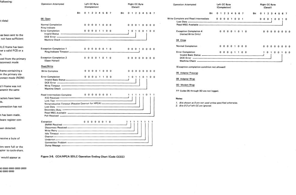
CCA/HPCA SDLC Operation Ending Chart (Code CCCC) 3-7
Sense Byte Breakdown Chart for CCA/HPCA SDLC (Code SSSS) 3-8
3274 Model A Attachment Information Breakdown Chart 3-9
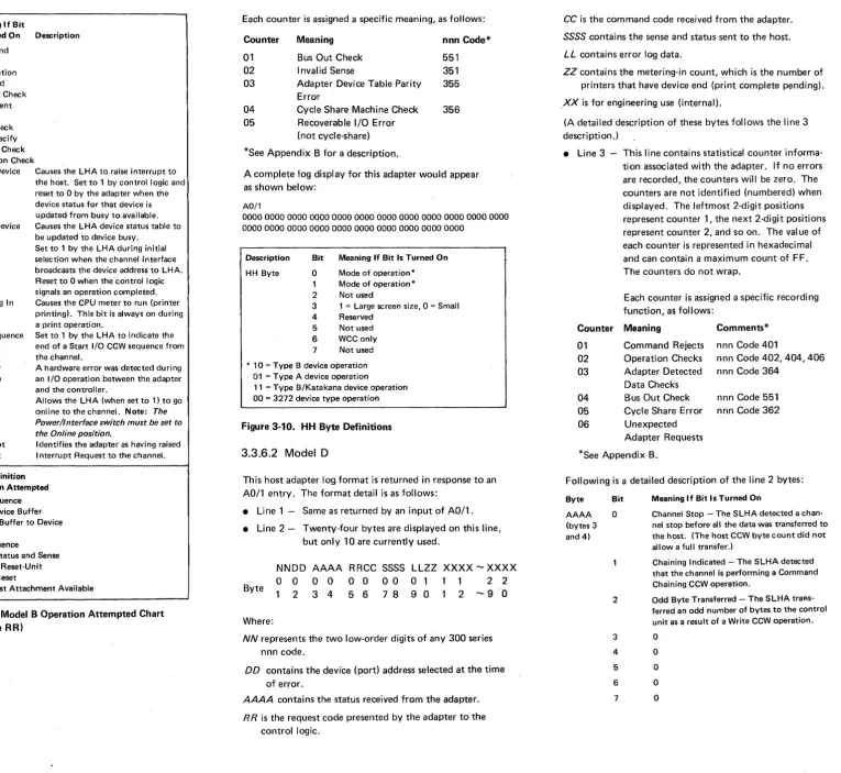
3274 Model B Operation Attempted Chart (Code RR) 3-10
HH Byte Definitions 3-10 Sense (SS) Byte Definitions 3-11
Type B Adapter Operation Attempted Chart (Code FF) 3-12
Type B Adapter Operation Ending Chart (Code CCCC) 3-12
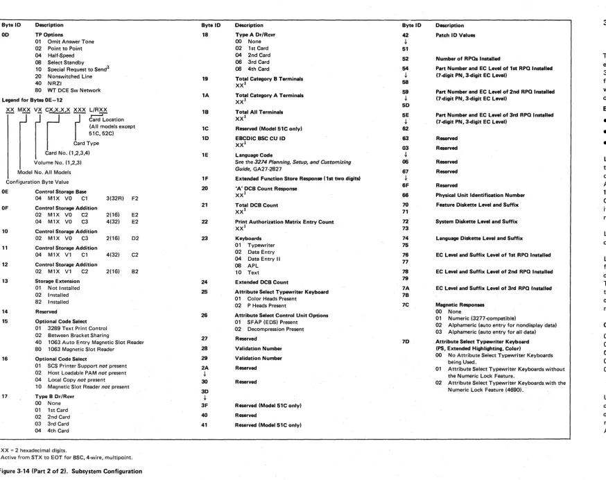
Figure 3-14. Subsystem Configuration (2 parts) 3-12 Figure 3-15. Test 6 Byte ID Chart 3-14
Figure 3-16. DCB Bit Definition Chart (2 parts) 3-15 Figure 4·J. IML Test Error Indications 4-1 Figure 4-2. ALT 1 IML Sequence 4-1
Figure 4-3. AL T 2 IML Sequence, Model C with Wrappable Modem 4-1
Figure 4-4. ALT 2 IML Sequence, Model C without Wrappable Modem 4-1
Figure 4-5. ALT 2 IML Sequence, Model A Local Channel Attachment 4-2
3-3 Figure 4-6. Figure 4-7. Figure 4-8. Figure 4-9. Figure 4-10. Figure 4-11. Figure 4-12. Figure 4-13. Figure 4-14. Figure 4-15. Figure 4-16. Figure 4-17. Figure 4-18. Figure 4-19. Figure 4-20. Figure 4-21. Figure 4-22. Figure 5-1. Figure 5-2. Figure 5-3. Figure 5-4. Figure 5-5.
Figure 5~6.
Figure 5-7. Figure 5-8. Figure 5-9. Figure 5-10. Figure 5-11. Figure 5-12. Figure 5-13.
Figure 5-14.
Figure 5-15. Figure 5-16. Figure 5-17. Figure 5-18. Figure 5-19. Figure 5-20. Figure 5-21. Figure 5-22. Figure 5-23. Figure 5-24.
ALT 2 IML Sequence, Model B Local Host Attachment 4-2
ALT 2 IML Sequence, Model D Local Host Attachment 4-2
AID2 Card Indicator for 2400-bps Integrated Modem 4-2
AID2 Card Indicator for 4800-bps Integrated Modem 4-2
AID2 Card Indicator for 9600-bps Integrated Modem 4-2
Example of Maximum Configuration of Error Message Content, Model A 4-3
T3274B OLT Routines 4-3 CDS Card Format, Model A 4-3
Example of Maximum Configuration of Error Message Content, Model B 4-4
T3274A OLT Routines 4-4
CDS Card Format, Models Band D 4-4 3274 Model C Online Tests 4-4 Operator Codes 4-6
Incident and Reflected Waves 4-7 Scope Setup 4-7
Measurement Points 4-7 Display Examples (2 parts) 4-8 Command Codes 5-1
Buffer Control Orders and Order Codes 5-2 United States EBCDIC I/O Interface Code for 3274 Control Unit and Attached 3277 Display Stations 5-3 United States EBCDIC I/O Interface Code for 3274 Control Unit and Attached 3262, 3278, 3279, 3287, and 3289 Terminals 5-3
United States ASCII I/O Interface Code for 3274 Control Unit and Attached 3262, 3278, 3279, 3287, and 3289 Terminals 54
Format of Write Control Character (WCC) Byte 5-4 Function of Write Control Character (WCC) Bits 54 Format of Copy Control Character (CCC) Byte 5-4 Function of Copy Control Character (Ccq Bits 5-4 Buffer Transfers for 3274 Model C (BSC) Copy Command Operation 5-5
Attention ID (AID) Configurations 5-5 Attribute Character Bits 5-6
3278 Top-Card Connector CE Jumper (Three Base Cards) 5-6
3278 Top-Card Connector CE Jumper (Two Base Cards) 5-6
3279 Top-Card Connector CE Jumper 5-6 3279 Base Field Attributes 5-6
Extended Field and Character Attributes 5-7 Attribute Character Bit Assignments for 3277s 5-7 Control Character I/O Codes 5-7
Initial Selection 5-8
Write - After Selection with Write Command 5-8 Read - After Selection with Read Command 5-8 Sense - After Selection with Sense Command (Issued in Response to Unit Check Status) 5-8
Status Byte Bit Assignments for 3274 Models Band
D 5-9
Figure 5-25. Sense Bit Description 5-9
Figure 5-26. Initial Status and Sense Conditions for 3274 Models Band D 5-10
SY27-2512-3
Figure 5-27. Ending Status and Sense Conditions for 3274 Models Band D 5-10
Figure 5-28. Asynchronous Status and Sense Conditions for 3274 Models Band D 5-11
Figure 5-29. General Poll and Specific Poll, Sequence/Response Diagram 5-13
Figure 5-30. 3274 Message Response to Polling or Read Modified Command 5-14
Figure 5-31. Selection Addressing, Sequence/Response Diagram 5-15
Figure 5-32. Write-Type a~d Control-Type Commands, Sequence/ Response Diagram 5-16
Figure 5-33. Read-Type Command, Sequence/Response Diagram 5-17
Figure 5-34. Remote Status and Sense Byte Definitions, BSC 5-18 Figure 5-35. Remote Error Status and Sense Responses, BSC 5-19 Figure 5-36. Remote 3270 BSC Status and Sense Conditions 5-20 Figure 5-37. 3274 Model A Local Command Codes 5-21
Figure 5~38. Status Definitions 5-22 Figure 5-39. Sense Definitions 5-22 Figure 5-40. Status Bit Conditions 5-22 Figure 541. Sense Bit Conditions 5-23
Figure 5-42. Initial Status and Sense Conditions, 3274 Model
A 5-23
Figure 5-43. Ending Status and Sense Conditions, 3274 Model A 5-23
Figure 5-44. Asynchronous Status and Sense Conditions, 3274 Model A 5-24
Figure 5-45. Nonsequenced Commands and Responses Supported by 3274 5~25
Figure 5-46. SDLC Commands and Responses in Hexadecimal Notation 5-25
Figure 5-47. Session Control Functions Supported by 3274 5-25 Figure 5-48. Data Flow Control Requests Supported by 3274 5-25 Figure 5-49. Transmission Header Format 5-26
Figure 5-50. Request/Reponse Header Format 5-26
Figure 5-51. SDLC/SNA Commands Required to Start Session with LU2 5-27
Figure 5-52. SDLC/SNA Exception Responses 5-28 Figure 5-53. Summary Table of LUSTATs 5-30
Figure 5-54. Command Reject (CMDR) Message Format 5-31 Figure 5-55. Switch and Control Explanation 5-31
Figure 5-56. BSC Readiness Symbols 5-32 Figure 5-57. SNA Readiness Symbols 5-33
Figure 5-58. Connection of 3274 Control Unit Model C with DDS Adapter Feature 5-34
Figure 5-59. Digital Data Wave shapes 5-34 Figure 6-1. TPLM Tab Pin Locations 6-1
I
CE Safety Practices
All Customer Engineers are expected to take every safety precaution possible and observe the following safety prac-tices while maintaining I BM equipment:
1. Do not work alone under hazardous conditions or around equipment with dangerous voltage. Always advise your manager if you MUST work alone. 2. Remove all AC and DC power when removing or
assembling major components, working in immediate area of power supplies, performing mechanical inspection of power supplies and installing changes in machine circuitry. Pull the power plug from the receptacle to remove power source.
3. Wall box power switch, when used to disconnect power, should be locked or tagged in off position. "Do not Operate" tags, form 229-1266, should be securely attached to power switch or to outside of power box. 4. When it is absolutely necessary to work on equipment
having exposed operating mechanical parts or exposed live electrical circuitry anywhere in the machine, the following precautions must be followed:
a. At least one other person familiar with power-off controls, emergency power-off procedures, and the location of the wall box power switch, must be in the immediate vicinity at all times.
b. Never wear rings, wrist watches, chains, bracelets, metal cuff links, etc.
c. Use only insulated pliers and screwdrivers. d. Keep one hand in pocket.
e. When using test instruments be certain they are of proper capacity and controls are set correctly. Use only insulated probes.
f. Avoid contacting ground potential (metal floor strips, machine frames, etc.; use suitable rubber mats, purchased locally if necessary).
5. Safety Glasses must be worn when:
a. Using a hammer to drive pins, riveting, staking, etc. b. Power hand drilling, reaming, grinding, etc. c. Using spring hooks, attaching springs. d. Soldering, wire cutting, removing steel bands. e. Using solvents, sprays, cleaners, chemicals, etc., to
clean parts.
f. All other conditions that may be hazardous to your eyes. REMEMBER, THEY ARE YOUR EYES. 6. Special safety instructions such as handling Cathode
Ray Tubes and extreme high voltages must be followed as outlined in CEMs and Safety Section of the Mainte-nance Manuals.
7. Do not use solvents, chemicals, greases or oils that have not been approved by IBM.
8. Avoid using tools or test equipment that have not been approved by IBM.
9. Replace worn or broken tools and test equipment. 10. The maximum load to be lifted is that which in your
opinion and that of management does not jeopardize your own health or well-being or that of other employees.
11. All safety devices such as guards, shields, signs, ground wires, etc., shall be restored after maintenance. 12. Each Customer Engineer is responsible to ensure that no
action on his part renders a product unsafe or exposes hazards to customer personnel.
13. Place removed machine covers in a safe, inaccessible place where no one can trip over them.
14. All machine covers must be in place before machine is returned to customer.
15. Always place CE tool kit away from walk areas (Le., under desk or table) where no one can trip over it. 16. Avoid touching mechanical moving parts (when
lubri-cating, checking for play, etc.).
17. When using stroboscope, do not touch ANYTHING -it may be moving.
18. Avoid wearing loose clothing that may be caught in machinery. Shirt sleeves must be left buttoned or rolled above the elbow.
19. Ties must be tucked in shirt or held by a tie clasp (preferably nonconductive) approximately 3 inches from end. Tie chains are not recommended. 20. Before powering up or starting equipment, make
certain other CEs and customer personnel are not in a hazardous position.
21. Maintain good housekeeping in area of machines while performing and after completing maintenance. 22. Even though preventive measures are taken, accidents
do occur. CEs and support personnel should be pre-pared to follow emergency first aid procedures as outlined below.
First Aid - General
1. If accidental electrocution occurs:
a. Remove power source before touching victim. b. If power cannot be removed, pull victim away from
equipment by using non-conductive material such as a broom handle, leather belt, or necktie.
c. Immediately begin rescue breathing (see below). d. Begin CPR if necessary and only if trained person is
available.
e. Call a doctor - Have someone summon medical aid. f. Remain in position - After victim revives, be ready
to resume respiration if necessary. 2. For serious injury:
a. Summon medical aid.
b. Do not move victim unless absolutely necessary to remove from danger.
c. Attempt to stop serious bleeding by using pressure points or a pressure bandage.
d. Loosen clothing and keep victim warm. Artificial Respiration
General Considerations
1. Start immediately - seconds count.
Do not wait or look for help or stop to loosen clothing. Warm the victim or apply stimulants.
2. Check mouth for obstructions; remove foreign objects; pull tongue forward.
Rescue Breathing for Adults - Place Victim on His Back Immediately
1. Clear throat of water, food, or foreign matter. 2. Tilt head back to open air passage.
3. Lift jaw up to keep tongue out of air passage. 4. Pinch nostrils to prevent air leakage when you blow. 5. Blow until you see chest rise.
6. Remove your lips and allow lungs to emp~y.
7. Listen for snoring and gurglings, signs of throat obstruction.
8. Repeat mouth-to-mouth breathings 10-20 times a minute. Continue rescue breathing until he breathes for himself, or medical aid arrives.
~
~inal
mouth-~"
to-mouthThumb and . ' . _posi"tion finger positions
Reprint Courtesy Mine Safety Appliances Co.
. /
."
•
Chapter 1. Maintenance Approach and
System
Overview'
This chapter contains information to assist the support customer engineer in isolating and correcting 3274 sub-system problems that cannot be attributed to a failing field replaceable unit (FRU). The information supplements existing documentation covering problem isolation, use of serviceability aids, specialized tools, and test equipment. The topics presented include the following:
• Overall Maintenance Approach: The maintenance
approach is outlined to provide flexibility both in the type of approach taken and in the selection of support-ing serviceability aids. The maintenance approach identifies and refers to procedures, tests, specialized tools, and test equipment that will most likely help isolate various types of 3274 problems. Detailed descrip-tions of these serviceability aids and their use are con-tained in other chapters in this publication. In addition, examples using these serviceability aids are given for typical 3274 problems.
• Subsystem Operation Overview: This overview gives a
general description of 3274 operations and functions.
• Serviceability Aids: A general description of service· ability aids and their use is given. These aids include the operational indicators, display symbols, error suffix codes, logouts, tests, test equipment, and host error recording.
• Reference Material: All supporting reference material in this publication is identified and described. This refer-ence material provides detailed descriptions of error recording and indications, tests, error recovery pro-cedures, 3270/3274 operational differences, error suffix code action chart, and tools and test equ ipment.
• Supporting Publications: Supporting I BM publications
are identified, and their contents briefly described.
• Procedure for Requesting Assistance: A procedure for
requesting assistance from the next level of the support structure is outlined. This procedure includes 3274 problem recording which will aid the support structure in problem determ ination.
1.1
MAINTENANCE APPROACH
This maintEmance approach is outl ined to provide flexibil-ity both in the type of approach taken and in the selection of supporting service aids. The approach used to isolate a specific 3274 problem may vary because of multiple error
indications and the type of operation being performed at the time the error occurred. Therefore, the maintenance approach to typical problems described in the following is not necessarily the only effective approach that could be used.
The suggested maintenance approach identifies and refers to various procedures, tests, tools, and test equipment that will most likely aid in isolation of the problem. This approach has four basic steps, which are performed in sequence:
Step 1
Review and verify the results obtained by the product cus-tomer engineer by using the following reference material:
• 3274 Problem Report Form
• 3274 Control Unit Maintenance Information
Step 2
Analyze operational indicators (842 1), display symbols, and error suffix codes (nnn codes).
Step 3
Analyze logouts, hang conditions, and failing operation sequences.
Step 4
Record all problem symptoms, and complete the Support Structure Information Form in preparation for requesting assistance. The effectiveness of the assista'nce wi II depend largely on the information that you provide.
These four steps are illustrated in Figure 1-1.
Step 1
Review/Verify Results Obtained by the Product Customer Engineer
Problem
-Isolated
and
Corrected
Step 2
Analyze: • Operational
Indicators • Display Symbols • Error Suffix
Codes
Perform Mach ine Checkout MAP 100
(in the 3274 MIM) to Verify Correct OperationlReturn 3274 to Customer
,
•
Analyze: • Logouts
Material
3274 Problem Report Form
• Complete If Necessary
3274 Maintenance Information
• Perform Isolation Procedure
Material
Chapter 2. Subsystem I ndicators, Symbols, and Messages
- Chapter 3. Subsystem Error Logs and Test Formats
Chapter 4. Subsystem Tests, External Tests, and Subsystem Service Aids Chapter 5. Reference Data
I
I
I
I
I
• Hang Conditions
_-.J
• Failing SequenceStep 4
Assistance Preparation depend largely on com-Effective assistance will plete and accurate recording of problem symptoms, and on completion of the Support Structure Information Form. • Record Symptoms
• Complete the Support Structure Information Form
• Contact the next level of the support structure for assistance.
See Appendix A.
The Support Structure will assist you in prob-lem determination. This assistance may include:
• SymptomlFix Search • Special Testing
Equipment • On-Site Assistance
Figure 1-1. Support Customer Engineer Maintenance Approach
SY27-2512-3
1.2 SUBSYSTEM DATA FLOW
The 3274 subsystem data flow consists of test data, con-trol data (unit code); status, error, and log data;·and mes-sage data between the components of the subsystem. Figure 1-2 ill~strates the 3274 subsystem configuration. The data flow is described as follows:
• Initial Machine Load (lML) of Test Data - Loading the 1M L test data residing on the system diskette into con-trol storage (paragraph 1.2.1 and Figure 1-3).
• Initial Machine Load (lML) of Unit Code - Loading the unit code residing on the system diskette into control storage (paragraph 1.2.2 and Figure 1-3).
Control Logic
Control Storage
Remote Attachment 3274 Model C
I
HPCA CCACCA
• Message Data Flow between 3274 Control Unit and Attached Devices - The flow of message data between the 3274 Control Unit and attached devices (paragraph 1.2.3 and Figure 1-4).
• Message Data Flow between 3274 Control Unit and Host System - The flow of message data between the 3274 Control Unit and the host system (paragraph 1.2.4 and Figure 1-5).
• Status, Error, and Log Data Flow - The flow of data from the 3274 Control Unit, the host system, and attached devices to the data control block area of con-trol storage (paragraph 1.2.5 and Figure 1-6).
SNA/SDLC
5
BSC
"
Local Channel Attachment 3274 Model A
Host System
33FD 33FD
Adapter
Figure 1-2. 3274 Subsystem Overview
SNA Version
Local Host Attachment 3274 Models Band D
3272 Version
Type.A Adapter
Type B Adapter
Channel
Channel
13262 Category A 13289 Devices
r
32873278/3279
Category B
I
3287/3288 DevicesJ
3284/32863277
1.2.1 IML Test Data Path
The IML test data path is shown in Figure 1-3. IML test data is retrieved from the 33FD after IML tests 0000, 0001, and 0002 have been successfully completed. IML test 0002 verifies that the 33FD and the 33FD adapter are function-ally operational. The data path, from origin to destination, is identified as follows:
• 33FD
• 33FD Adapter
• Bus
• Control logic
• Control storage
Control Logic
Control Storage
)
Control Code
t:;:!=::Lt::!=~ Area
33FD Adapter
Figure 1-3. Initial Machine Load Data Flow
,
Remote Attachment 3274 Model C
HPCA CCA
CCA
Local Channel Attachment 3274 Model A
SNA Version
Local Host Attachment 3274 Models Band D
3272 Version
Type A Adapter
Type B Adapter
..
1-2
1.2.2 1M L of Unit Code
The data path of IML (loading of unit code) is the same as the IML test data path. Unit code is normally loaded after the IML tests have been successfully completed. Placing the AL T switch in the AL T 1 position and pressing the 1 M L pushbutton will cause the IML test to be bypassed and initi-ate loading of the unit code.
SNA/SDLC
S
BSC
i
Channel
Channel
Category A
Host System
Devices ~~~--,
Category B 3287/3288 Devices 3284/3286
1.2.3 Message Data Flow between 3274 Control
Unit and Attached Devices
Message data flow between the 3274 Control Unit and attached devices is shown in Figure 1-4. The message data paths, from origin to destination, are identified as follows:
~
Remote Attachment
Controi Logic 3274 Model C
"
I
HPCACCA
~ ~
-Control Storage
~
)
M.".ge
Buffer
Area CCA
•
3274 Control Unit Device to 3274
to Device Control Unit
•
Control storage • Category A or B device(message buffer area)
•
Type A or B adapter• Control logic
• Bus
• Bus • Control logic
• Type A or B adapter • Control storage
• Category A or B device (message buffer area)
SNA/SDLC
S
BSC
S
Local Channel Attachment Host
System 3274 Model A
'"
:::I
In
SNA Channel
Version
Local Host Attachment 3274 Models Band D
3272
Channel Version
.
It33FD 33FD
Adapter
~
13262
, Category A 13289
Devices '3287
3278/3279 ~ Type A
I
-Adapter ~
Category B
I
3287/3288 Devices I 3284/3286;3277 Type B
~
Adapter
r-Figure 1-4. Message_ D~ta Flow between 3274 ~ntrol Unit and Devices
1.2.4 Message Data Flow between 3274 Control
Unit and Host System
Message data flow between the 3274 Control Unit and the host system is shown in Figure 1-5. The message data paths, from origin to destination, are identified as follows:
Remote Attachment Control Logic
'"
3274 Model C
~
1 HPCA·. CCA~
Control Storage
) M.ss.ge Buff., ~
r.r_~ In
I~~
Area
--
CCALocal Channel Attachment 3274 Model A
SNA Version
Local Host Attachment 3274 Models Band D
3272
3274 Control Unit to Host
• Control storage (message buffe~ area) • Control logic
• Bus
• Remote host adapter/ local channel attachment or local host attachment
• Host system
SNA/SDLC
S
.,.
BSC
,
....
Channel
Host to 3274 Control Unit
• Host system
• Remote host adapter/ local channel attach-ment or local host attachment
• Bus
• Control logic
• Control storage (message buffer area)
Host System
- - - -
Channel...
-
..
Version33FD 33FD
Adapter
13282
Category A 13289 Devices J3287
3278/3279
-Type A
-Adapter
r-Category B 13287/3288
Devices I 328413286
3277 Type B
~
0-Adapter ~
Figure 1-5. Message D~ta Flow between 3274 Control Unit and Host System
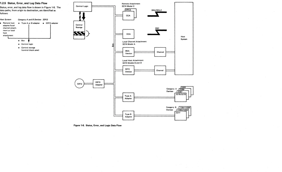
1.2.5 Status, Error, and Log Data Flow
Status. error, and log data flow is shown in Figure 1-6. The data paths, from origin to destination. ate identified as. follows:
Host System • Remote host
adapter Ilocal channel attach-ment or local host attachment
Category A and B Devices 33FD
• Type A or B adapter • 33FD adapter
• Bus
• Control logic • Control storage
(control block area)
Control Logic
,
Control Storage~
)
en
:l
co
33FD
33FD Adapter
Figure 1-6. Status. Error. and Logic Data Flow
SY27-2512-3
Remote Attachment 3274 Model C
IHPCA CCA
I-CCA
Local Channel Attachment 3274 Model A
SNA Version
Local Host Attachment 3274 Models Band D
3272 Version
Type A Adapter
Type B Adapter
1-4
SNA/SDLC
,
BSC
S;
Host
, System
Channel
Channel
13262 Category A I 3289 Devices 13287
3278/3279
I
-
I-Category B 13287/3288 Devices
J
3284/32863277
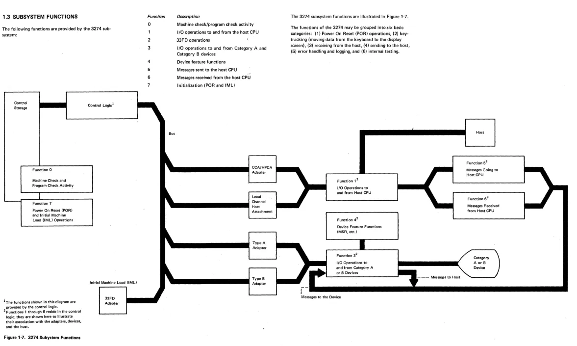
[image:10.1235.70.1193.47.732.2]f-1.3 SUBSYSTEM FUNCTIONS
The following functions are provided by the 3274 sub-system:
Control Storage
Function 0
Machine Check and Program Check Activity
Function 7
Power On Reset (POR) and Initial Machine Load (IML) Operations
1The functions shown in this diagram are provided by the control logic.
[image:11.1238.29.1207.58.763.2]2 Functions , through 6 reside in the control logic; they are shown here to illustrate their association with the adapters, devices, and the host.
Figure 1·7. 3274 Subystem Functions
Control Logic1
33FD Adapter
, Function
o
2
3
4
5
6
7
Bus
Description
Machine check/program check activity
I/O operations to and from the host CPU
33FD operations
I/O operations to and from Category A and Category B devices
Device feature functions
Messages sent to the host CPU
Messages received from the host CPU
Initialization (POR and IML)
The 3274 subsystem functions are illustrated in Figure 1-7.
The functions of the 3274 may be grouped into.six basic categories: (1) Power On Reset (POR) operations, (2) key-tracking (moving data from the keyboard to the display screen), (3) receiving from the host, (4) sending to the host, (5) error handling and logging, and (6) internal testing.
Function
,2
I/O Operations to and from Host CPUFunction 42
Device Feature Functions (MSR, etc.l
Function 32
I/O Operations to and from Category A or B Devices
Messages to the Device
SY27-2512-3 '
- - - Messages to Host
Host
Function 52 Messages Going to Host CPU
1.3.1 Control Unit Power-On Reset
When the 3274 is powered on, the +5 V dc supply origin-ating at the low-voltage power supply (LVPS) provides input to the PO R circuit at L VPS card point E 15. The POR signal is then generated to the 01 A-A 1 board as out-put from LVPS card point El. POR to the A1 board generates a restart to the control logic and subsequently starts a normal 1M L sequence.
1.3.2 Keystroke Handling
The requests and status from the attached devices are handled ~y the Keystroke control function. When an operator1presses a key, the keyed data is read by the dis-play base card 1, which, if it receives a poll, sends the data to the terminal adapter (Category A devices only). The terminal adapter then loads the status and scan code of the actuated key into a queue. The terminal adapter control retrieves this infor· mation from the buffer queue.
"Keystroke control converts the scan code and distributes the data to the appropriate functions. See Figure 1-8 for an illustration of Type A adapter keystroke handling.
SY27 ·2512·3
As an example of keystroke handling, when a graphic char-acter key is pressed, the graphic key scan code is converted into internal code and then into regen code by means of a language code conversion table. The converted regen code is moved into the device regen buffer, after which the graphic character keyed may be seen displayed on the screen.
When a device is polled, if it has an error condition or request from a feature (selector pen, MSR), it sends status to the terminal adapter, and key tracking control handles the status as it does a status preceding keyed data.
An error condition detected by the device is signaled to the terminal adapter when the device is polled. Error condi-tions are (1) device check (a parity error was detected in the regen buffer), (2) keyboard overrun (keystrokes too close together) , and (3) feature timeout (no response from the feature card within the expected time).
Special keyboard scan codes are used for the device POR signal and keyboard overrun conditions. Selector-pen data is sent to the terminal adapter by read commands. The row count is sent on the first read, and the field count is sent on the second.
,
To Control Logic
I/O Tags - 8421 Indicators
...
~..
I/O Bus 0
To
~
Bus 0 ~Bus 0 Bidirectional " >
")
--..
--..
DIR Select~
...
~ ...Decode
..
... Driver/Gating
..
..
.
-
..
and Receiver
Driver/Receiver Car
Timings Address
~ Decode
..
Transmit OSC..
Receive4,.
~ Clock
~ ~
I
,
..
..
I/O Bus 1
---
Coax...
Transmit Clock~
Bus 1 ~ Tag SyncI
...
Line-< - Bidirectional ... 2..-
L
Bus 1 " .8 4 2 1 Indicators Clock
;>
..
Control~
...
~ .....
Decode
Gating
;>
and MiscellaneousI
.... Receive~
..
andReceive Data
..
:.... Receive Data Timings..
l
....
....J
•
~~V'7
....
1
;>
Data ~..
~,
..
...
Buffer...
Coax
---
r - -;>
and ~..
..
Transmit Line Transmit Data
.
...
--..
...
r.:!>
Controls SERDES* SERDES* Data..
Control..
Control Transmit
..
Poll, Read...
..
..
Write Control
~ 7
IV
I
•
*Serializer/Deserializer..
...
Bus 0 SERDES*
<A.~ Decode A
t ! '
-and
"
~Bus 1
....
...
OutputBuffer
....
K
<
-
.
;>
~. Figure 1-8. Keystroke Handling, Type A Adapter
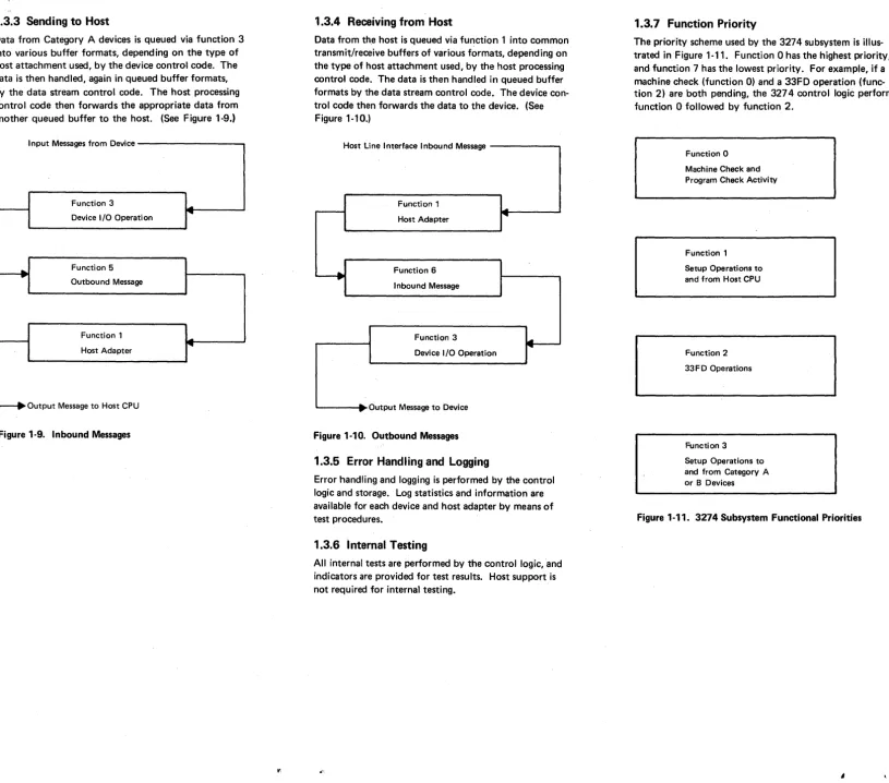
1.3.3 Sending to Host
Data from Category A devices is queued via function 3 into various buffer formats, depending on the type of host attachment used, by the device control code. The data is then handled, again in queued buffer formats, by the data stream control code. The host processing contro I code then forwards the appropriate data from another queued buffer to the host. (See Figure 1-9.)
Input Messages from Device
Function 3
...
r - - -
....
Device I/O Operation~ Function 5
Outbound Message
Function 1 r
-~
Host Adapter
[image:14.1233.75.890.41.759.2]~ Output Message to Host CPU
Figure 1-9. Inbound Messages
1.3.4 Receiving from Host
Data from th~ host is queued via function 1 into common transmit/receive buffers of various formats, depending on the type of host attachment used, by the host processing control code. The data is then handled in queued buffer formats by the data stream control code. The device con-trol code then forwards the data to the device. (See Figure 1-10.)
Host line nterface Inbound Message
Function 1
..
r - - - I~
Host Adapter
~ Function 6
Inbound Message
Function 3
I.11III.
~
Device I/O Operation
-:- Output Message to Device
Figure 1-10. Outbound Messages
1.3.5 Error Handling and Logging
Error handling and logging is performed by the control logic and storage. Log statistics and information are available for each device and host adapter by means of test procedures.
1.3.6 Internal Testing
All internal tests are performed by the control logic, and indicators are provided for test results. Host support is not required for internal testing.
SY27 -2512-3
1.3.7 Function Priority
The priority scheme used by the 3274 subsystem is illus-trated in Figure 1-11. Function 0 has the highest priority, and function 7 has the lowest priority. For example, if a machine check (function 0) and a 33FD operation (func-tion 2) are both pending, the 3274 control logic performs function 0 followed by function 2.
Function 0 Machine Check and Program Check Activity
Function 1 Setup Operations to and from Host CPU
Function 2 33FD Operations
Function 3
Setup Operations to and from Category A or B Devices
Figure 1·11. 3274 Subsystem Functional Priorities
Function 4
Device Feature Functions (MSR, etc.)
Function 5 Messages Going to Host CPU
Function 6 Messages Received from Host CPU
Function 7 POR Operations and IML
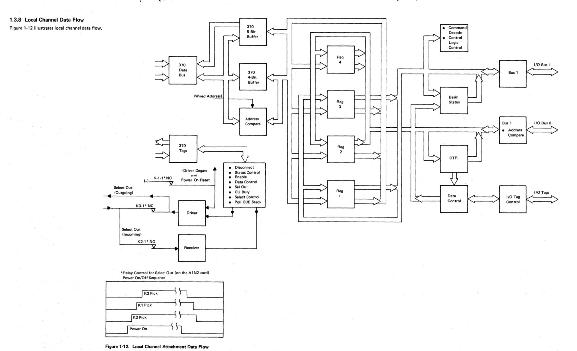
1.3.8 Local Channel Data Flow
Figure 1~12 illustrates local channel data flow.
=>
=>
¢ :
~
K
( - ) -·1-1* NC
Select Out (Outgoing)
K3·1 * NC
Select Out (Incoming)
K2-1* NO
V
..
....
370
<=-Data Bus
«'
'""(Wi red Address)
-370
....
Tags
K
....
-Driver Degate ~. and
Power On Reset
~
Driver
•
Receiver
*Relay.Control for Select Out (on the A 1 N2 card) Power On/Off Sequence
K3 Pick K1 Pick K2 Pick Power On
Figure 1·12. Local Channel Attachment Data Flow
370
~
5·Bitir=>
Buffer-370
~
4·Bit...
~
Buffer
r
-+
L , - - !---r--
-~
Address~
Compare
D
"""-
r--• Disconnect
•
Status Control•
Enable•
Data Control • Set Out • CU Busy• Select Control
"--• Po" CUE Stack '
-+
~,• Command Decode
~
• Controlb
Logic~
ControlReg
~
4~
I/O Bus 1....
~ ~"
V\:<;." ... /
Bus 1"-~ ~
~
=>
-
~~
Basic I--
~Reg "- Status
----=>
3h:2
:>
-Bus 1 I/O Bus 0
' - - -
-
r - -s..~
• Address
~
>
['211
-
r - - :---"'11\ ...
-Compare
"
~
Reg...
i.~ 2
.. "L
L.:>
. / CTR
-
""""--U
....
~
>
.... Reg I/O Tags
... 1
~
r
Data/
~
I/O Tag....
....
~ . / Control
"-
K
'""
...
Control "...
-
...
1.3.9 Type A Adapter Coax Data Path
Figure 1-13 illustrates the bit path from the coax to the
Type A adapter.
Adapter States
1. Disabled
2. Enabled but Idle (Normal Polling)
Operator Panel Indicators
Control
Logic and I---i
Storage
Type A Adapter
I/O Buffer
SERDES
3. Enabled Working (Passing Normal. Data/Keystroke Activity)
Driver/Receiver
Bit Serial Coax
~I
To Devices
Figure 1-13. Coax to Type A Adapter Data Flow
Bit Parallel
12-Bit Word Format
1123456 7 8 9 10 11112
Sync Parity
SY27 -2512-3
1.4 SUPPORTING PUBLICATIONS
Additional information relating to ~he IBM 3274 Control Unit, Models A, B, C, and D is presented in IBM 3270 Information Display System Library Users Guide,
GA23-0058.
Chapter 2. Subsystem Indicators, Symbols, and Messages
2.1 INTRODUCTION
This chapter provides information concerning the operator panel indicators and the 3278 display symbols and messages used to convey error and subsystem status conditions to the user and to the customer engineer. The operator panel indicators include the 8 4 2 1 indicators, the DC ON indi-cator, and the ONLINE/OFFLINE indicator (3274 Models A, 8, and D only).
The subsystem symbols and messages displayed on the 3278 status line include the Readiness and System Connec-tion symbols, Do Not Enter messages, CommunicaConnec-tion Reminders, Shifts and Modes symbols, Printer Status mes-sages, and Machine, Program, and Communication Check numbers. The functional details of each item are described.
2.2 842 1 INDICATORS
The four indicators labeled 84 2 1 (Figure 2-1) are located on the operator panel. They are activated by the control logic to serve as prompting, progress, and/or success/failure indicators during the following operations:
• IML Bus Test: All four indicators are turned on by the IML pushbutt?n via the control logic and the Type A adapter card (01 A 1 S2) if there is no activity on the internal logic bus.
• IML Tests: As the test routines are run, the control logic turns on and turns off each of the four indicators. A failure condition is indicated by a constant or flashing code displayed in the 84 2 1 indicators. The success of a given test is indicated by the 8 4 2 1 indicators pro-gressing to the next hexadecimal value.
• Operational Mode: During online operations with the
host CPU, the 84 2 1 indicators are turned on by the control logic when an error condition is detected by the control logic. Hexadecimal values are used to indicate the most likely failing component. If additional errors are detected the control logic writes over the prior indi-cation with the new hexadecimal value. The indicators turned on by the control logic may represent recoverable errors or nonrecoverable errors. The error remains dis-played in the 842 1 indicators until the machine is powered off or until the IML pushbutton is pressed.
• Customizing Mode: During customizing, the 842 1
indicators display the type of customizing operation in progress, as well as serving as progress and procedural-failure indicators. They also prompt the user to change diskettes during customizing and notify the user when customizing is completed.
• Installation Mode: During initial installation, the 842 1 indicators are used to indicate a successful test run after initial machine power-on has occurred. They are also used to show the state of the local channel interface when attempting to run online tests (OL Ts) during initial installation.
2.3 DC ON INDICATOR
The DC ON indicator is located on the operator panel PC board. It is turned on by +5 Vdc from fuse F1 (20A circuit) on the LVPS PC board via the 21 cable to the operator panel. Loss of +5 Vdc at the 01 A 1 logic board will turn qff the indicator. This indicator is not related to the POR circuit and does not indicate the status of +5 Vdc to the 33F D drive or the 01 A2 feature board.
SY27-2S12-3 :
Bus Test Control S2
-IML Pushbutton -8 On
Logic Card
" " " - --4 On
-
-2 On...--r---
-1 OnIML Tests
Operational Mode
Customizing Mode
[image:17.1232.307.1167.47.738.2]Installation Mode
SV27-2512-3
2-2
2.4 ONLINE/OFFLINE INDICATOR AND
SWITCH FOR MODELS A, B, AND D
A description of the switch and indicator function for Models A, B, and D follows. There are no rotary switches on the Model C units.
2.4.1 Model A
Positioning the Power/Interface rotary switch to ONLINE causes the following (Figure 2-2):
• An exclusive OR function
fJ
gives output because the trigger0
and the Online/Offline switch donot
agree. • The output is interpreted as a request for change in thestate of the trigger
D.
• A function is, in turn,sent and interpreted to toggle the trigger
D .
• Toggling the trigger
D
causes the OFFLINE indicator to turn off and deactivates the 1M L pushbutton.IML Pushbutton ~>
Positioning the Power/Interface rotary switch to OFFLINE causes the same operation; this time, however, toggling the trigger
D
to the opposite state-turnson
the OFFLINE indicator and enables the IML pushbutton to function.Use one of the following procedures to force the 3274 offline:
1. If the 3274 will not go offline (the OFFLINE indicator will not come on), request that the host CPU be stopped. Power the 3274 off, and restart the host CPU.
2. Momentarily ground the pin:
Model A: Al-P2D10
A IML Load
...J S2M07
II
!>
r-OFFLINE Indicator
P2U10
A T
I
II
PORD
P2D10
Interrupt to
Q)
Microcode '0
0
..
(Je
XOR (J
~
ONLINE/OFFLINE Switch
fJ
N2M13 P2J09
Toggle ONLINE/OFFLINE trigger Notes:
1. If latch and switch do not agree, interrupt microcode. 2. Only accept toggle control code if latch and switch agree.
Figure 2-2. ONLINE/OFFLINE Control Logic, Model A
2.4.2 Models Band D
Positioning the Power/Interface rotary switch to ONLINE causes the following (Figure 2-3):
•. Switch Online and Microcrode Online condition AND
fJ '
which is sampled by a sync pulse to set onlinelatch
D.
• Setting the online latch turns off the OFFLINE indica-tor and deactivates the 1M L pushbutton.
Positioning the Power/Interface rotary switch to OFFLINE deconditionsAND
0,
causing latchD
to be reset with the next sample pulse. Resetting the online/offline latch turns on the indicator and enables the IML pushbutton to function. It should be pointed out that internal control-logic checks may also cause the 3274 Model B or D to go offline .Microcode Online
Switch Online
A
fJ
A
A
Logic Timing
Signal
---4.---f. __
---lUse one of the following procedures to force the 3274 offline:
1.
If the 3274 will not go offline (the OFFLINE indicator will not come on), request that the host CPU be stopped. Power the 3274 off, and restart the host CPU.2. Momentarily ground the pin:
Model B: A 1-02B07 Model D: A 1-02G05
OFFLINE Indicator
ONLINE/OFFLINE
L P2U10
D
When control logic detects
failure
---tI
IML LoadA S2M07
IML Pushbutton
2.5 OPERATOR INFORMATION AREA
LAYOUT
The operator information area consists of five key fields located below the 3278/3279 status line. These five fields are not displayed on any Category B device (3277). The fields are (1) Readiness and System Connection, (2) Do Not Enter, (3) Reminders, (4) Shifts and Modes, and (5) Printer Status. The field lengths are shown in Figure 2-4.
Readiness and Do Not Enter Reminders System Connection (Input Inhibited)
1 6 9 17 21
Figure 2-4. Operator Information Area Layout
Shifts and Modes Printer Status
27 37 41 60 64
2.5.1 Readiness and System Connection Symbols
The first six positions of the status line are allocated to Subsystem Ready, Host Ready, Application Ready, and Test. See Figure 2-5.
Symbol
B1
•
TEST
Name 3274 Ready
Online A Online B
My Job
System Operator
Unowned
Test
Explanation
1 of the operator information areawhen the 3274
BI
Control Unit to which the display is attached is ready (functional) and the display is ready.The Online A and Online B symbols govern transactions with the host system. Certain keyboard functio~ and the n'leaning of some operator information area symbols differ depending upon which set of rules is applicable.
Online A. The control unit is connected to the system under!!. rules. The A symbol appears in remote systems using BSC protocol, in locally attached systems that use 3274 Models Band D. It is turned on by receipt of the follow-ing commands: Write, Erase/Write, Erase All Unprotected, Copy, Read Modi-fied, and Read Buffer.
The
.a
symbol is turned off when1. An operator action causes host communication. 2. The display station is turned off.
3. The NormallTest switch is placed in Test, or the TEST key is pressed to place the 3274 in Test mode.
Online B. The control unit is connected to the system under!! rules. The B symbol appears in systems that use SNA protocol. It is turned on by
~mpletion of an ACTPU/ACTLU command sequence, and is turned off by execution of DACTPU or DACTLU, including an internal DACTPU sequence, and when the NormallTest switch is placed in Test or the TEST key is pressed .
The display station is connected to the operator's application program. This symbol is displayed in position 3. This symbol appears in systems that use BSC or SNA protocol, or in systems that use 3274 Models Band D. In systems using BSC or the 3274 Models Band 0, it is turned on with the A symbol, and is turned off when power is removed, and when the Normal/Test switch is placed in Test. When using SNA protocol, it is turned on when the operator's application session owns the screen.
This symbol is used with SNA protocol and indicates that the system operator (SSCP Control Program) session owns the display screen. Except for the ENTER key, the Program Attention keys are not functional when this symbol is displayed.
The display station is connected to the system (using SNA only), but not to the operator's application program or to the system operator (control program). The SYS REO key is used if LOGON is required. This symbol is displayed in position 3.
The display station is in Test mode. Test mode is initiated or terminated by pressing the TEST key while holding the AL T key. TEST is displayed in positions 3 through 6. Test procedures are described in the IBM 3270 Informa-tion Display System: 3278 Displav Station Problem Determination Guide,
GA27-2839.
Figure 2-5. Readiness and System Connection Symbols (Locations 1 through 6)
SY27-2512-3
2.5.2 Do Not Enter (Input Inhibited) Symbols
The symbols shown in Figure 2-6 appear in positions 9 through 17 of the operator information area. Most of these symbols indicate an operator error. However, there are three categories of Do Not Enter symbols that are directly related to hardware or program failur~s: machine checks
All the Do Not Enter symbols are shown in Figure 2-6. All the symbols contain an X in posi.tion 9 (do not enter), combined with other symbols in positions 11 through 17, which define why input is disabled. The keyboard does not lock, but a change in state of the keyboard clicker (on-to-off or (on-to-off-to-on) indicates that the keyboard is disabled.
()(
~L program checks ()(PROG\),
and communication checks ()( ~~. Each of these symbols is accompanied by a 3-digit code that further defines the erro r. The codes are defined in paragraphs 2.5.6, 2.5.7, and 2.5.8.The following symbols are arranged in descending order of assigned priority. In case of multiple conditions, the higher-priority symbol is displayed.
Symbol
)(C>-.!
nnn
Name
Secu rity Key
Machine Check
Unavailable
)(
~nnn Communication Check)( PROGnnn
Program Check)( ::ba?
)(
*"+?
)(
*'+?
)(
*,..,+?
)(
* .. +?
)(
*J+?
)(
+-*~Questionable Card
Operator Unauthorized
Accent Plus What
Go Elsewhere
Explanation
The security key is turned off, and no operator input can be accepted. When the key is turned on, this symbol disappears, but any other preexisting "do not enter" condition may then be displayed.
The display station is not working properly. The symbol is accompanied by up to three digits, nnn (3278), which define the probable cause of the problem. Recovery procedures depend upon the type of error.
The control unit is not equipped to handle a feature that has been invoked. RESET should be pressed and another action initiated. (See Appendix B.)
A communication link error was detected and data cannot be sent. The RESET key should be pressed. This symbol is accompanied by up to three digits, nnn (3278), which define the probable cause of the problem. The communication reminder symbol is displayed as long as the condition exists.
A programming error was detected in the data received by the control unit. RESET should be pressed, and the operation should be retried. This symbol is accompanied by up to three digits which define the probable cause of the problem.
The wrong magnetic stripe card was used with the MSR. RESET should be pressed, and the correct MSR card should be used.
The operator has attempted to perform an unauthorized function. RESET should be pressed to restore the keyboard. The printer status area (locations 60 through 64) should be checked for printer assignment. If the Operator Unautho-rized symbol was displayed after the print key or I DENT key was pressed, a printer is not assigned. (If the Printer Assignment symbol is displayed in the printer status area, there is an error in the authorization matrix.) If the Operator Unauthorized symbol was displayed after the I DENT key was pressed and two numbers were entered, the operator is not authorized to use the printer.
These symbols indicate that an invalid dead key/character combination was entered (Canadian French keyboard only). RESET should be pressed to restore the keyboard, and a valid dead key/character combination should be entered. Valid combinations are as follows:
,
\ \ \,
\U
a A e E u
I I
~
e
1\
,..
~ ~
E
{;-
d
A Aa u U
..
e
E
i,
'j..
uG
c c c
,
"
,
An action has been attempted that is invalid for the display screen location. RESET should be pressed, and either the cursor should be moved or some other action should be taken.
Figure 2-6. Do-Not-Enter Symbols (Locations 9 through 17)
Symbol
)( SYSTEM
)( ?+
)(
c-c.::(.:.
~I)( ((:.
)(
-s
)(-f
)(
-f
*
)(
*>
)(
***?
)(
*NUM
Name
Message Received
System Lock
What (Try Again)
Printer Not Working
Printer Busy
Printer Very Busy
Time
Minus Symbol
Minus Function
Minus Function
More Than
What Number
Numeric
Explanation
A message from the control operator was received and rejected. RESET should be pressed to restore the keyboard. The operator may view the message by pressing SYS REO or may defer viewing of the message until a later time.
The system has disabled the keyboard following an entry. The operator should look for a message and then press RESET to restore the keyboard. ~
2-4
The last input was not accepted. The screen should be rechecked, and the opera-tion should be retried as follows:
1. Do not key while the X is displayed.
2. If AL T, or a shift key, was used, press the key again; then press RESET and retry the operation.
3. If AL T, or a shift key, was not used, press RESET and retry the operation.
The printer assigned to the display station is not functioning. If this symbol appears after the Print key has been pressed, the print request is canceled, and the DEV CNCL key should be pressed to restore the keyboard. If the Printer Failure symbol is displayed in the printer status areas, the printer stopped during the last print operation. DEV CNCL should be pressed to restore the keyboard and to instruct the control unit to stop monitoring the operations of the printer that stopped.
The printer assigned to the display station is busy. If the Printer Printing symbol is displayed in the printer status area, the printer is printing. The operator may wait for the printer operation to complete, or he may press the DEV CNCL key. If the print key was used, it may be possible to select another printer.
This symbol means the same as Device Busy, except that more time than usual is anticipated before the print request is accepted.
Time is required for the system to perform a function.
The symbol you keyed is not available. The RESET key should be pressed to restore the keyboard.
A currently unavailable function was requested. RESET should be pressed to restore the keyboard.
Operator Unauthorized
An attempt was made to enter more information into a field than can be entered. RESET should be pressed to restore the keyboard, and the operation should be retried and the entry corrected.
A numeral was entered that is unacceptable at the display screen location. RESET should be pressed to r~store the keyboard, and the correct entry should be made.