Systems Reference Library
System Operation Reference Manual
111M 1401 Data Processing System
IBM 1460 Data Processing System
File Number 1401/1460-01
Form A24-3067-2
This reference publication contains the introduction and basic
instruction set for the IBM 1401 and IBM
1460. The operation code
for each instruction is given in actual and mnemonic form, with
examples of each. The formula for calculating the execution time
of each instruction is also included.
In addition, this manual presents the instructions and applicable
timings for the
IBM1402, 1403, 1406, and 1447. For general
information on the units attached to the 1401 and 1460 systems,
refer to the
IBM 1401 and 1460 Bibliography,
Form A24-1495.
This manual is the first of five reference manuals providing the
complete instruction set for the IBM 1401 and 1460. The other four
manuals are:
Miscellaneous Input/Ouput Instructions (A24-3068)
Tape Input/Output Instructions (A24-3069)
Disk Input/Output Instructions (A24-3070)
Special Feature Instructions (A24-3071)
To accommodate a particular system configuration, any
Preface
This publication is the primary reference text for the
IBM1401 and 1460 Data Processing Systems. The full
set of manuals provides a detailed explanation of all
the instructions used by the system to manipulate data.
Detailed explanations of the instructions used with
the required and available input/output units attached
to the system are also included. The reader should be
familiar with the IBAf 1401 System Summary, Form
A24-1401, or the IBM 1460 System Summary, Form
A24-1496, and the various publications on
program-ming material, such as Symbolic Programprogram-ming System
(SPS) and Autocoder.
The complete manual is divided functionally into
these sections:
System Operation Reference Manual (A24-3067)
Section A Introduction
Section
B
System Operations
Section C
IBM1406 Operations
Section D
IBM1447 Operations
Section
E
IBM1402 and 1403 Operations
Section
N
Code Chart and Index of Instructions
Third Edition (September 1966)
This edition, A24-3067 -2, is a major revision of and obsoletes A24-3067 -1.
This revision does not obsolete the four companion reference manuals listed in thc Preface.
Significant changes are indicated as follows:
1. A dot (.) appears beside the l1age number when the entire page should be reviewed.
2. A vertical line (J) appears beside changed or added text. 3. A dot appears to thc left of a figure title when the entire
figure should be reviewed.
Tape Input/Output Instructions (A24-3069)
Section F Tape Input/Output Operations
Disk Input/Output Instructions (A24-3070)
Section G Disk Input/Output Operations
Miscellaneous Input/Output Instructions (A24-3068)
Section II Miscellaneous Input/Output
Opera-tions
Special Feature Instructions (A24-3071)
Section I Special Feature Operations
A System Reference Library can be compiled using
those sections applicable to the user's machine
con-figuration.
This publication is intended for programmers and
systems personnel who have a general knowledge of
the
IBM1401 or 1460 Data Processing Systems and who
require a reference tcxt for detailed information.
Other publications referenced here are, in most
cases, prerequisites for a complete understanding of
the material presented in this publication.
Copies of this and other IUM publications can be obtained through IUM Branch Offiees. This Manual has bcen prepared by the IBM Systems Development Division,
Product Publications, Dept. 171, P.O. Box 6, Endicott, N. Y. 13760.
Contents
IBM 1401 Data Processing System
IBM 1460 Data Processing System ... A-I
Introduction ... A-I Processing ... A-3 Stored Program Instructions ... A-5 Addressing ... ... ... ... ... ... A-7 Address Modification ... ... ... ... ... A-9 System Register Operation ... A-I0
Syste·m
Operations ... " ... B-1Arithmetic Operations ... " ...
B-2 True Add ... ... ... ... ... B-2 Complement Add ... ... ... ... ... ... ... B-3 Arithmetic Instructions ... B-4Logic Operations ... ...
B-8 Logic Instructions ... " ... B-9Data-Moving Operations .. " ...
B-12 Data-Moving Instructions ... B-12M,iscellaneous Operations ...
B-16 Miscellaneous Instructions ... B-16Edit Operation ... ... ... ... ...
B-20 IBM 1406 Operations ... " ... C-l Addressing ... C-lIBM 1406 Storage Unit Instructions ... C-l
Address Modification - Using the Modify
Address Instruction ... C-3 IBM 1447 Operations ... D-l Console Instruction Format .. ... ... ... D-2
IBM 1447 IConsole Instructions ... D-2 IBM 1402 and 1403 Operations ... E-l IBM
1402 Card Read-Punch Operations ...
E-lIBM 1402 Card Read-Punch Instructions ... E-2
Card .Read-Punch Timing ... ... ... ... ... E-7 Interleaving Input-Output Operations ... .... E-8 IBM
1403 Printer Operations ...
E-9IBM 1403 Printer Instructions ... E-I0 Carriage-Tape-Punch Considerations ... E-13 Combination Instructions ... E-15
IBM 1403 Printer Timings ... E-17
I
1401
1460
The
I1BM1401 Data Processing System and the
com-patible, more powerful,
IBM1460 Data Processing
System are high-speed, solid-state processing systems
having the program flexibility of larger systems.
Both the 1401 and the 1460 provide system
config-urations for processing unit records, magnetic tape and
magnetic disk records, and character-sensed
docu-ments. The three basic types of 1401 and 1460 systems
are card-, tape-, and disk-storage-oriented systems.
A card-oriented 1401, 1460 system is especially
use-ful when large volumes of card documents are used as
source data and output data, with particular advantage
in applications that involve the re-entry of data.
A tape-oriented 1401, 1460 system, designed to
han-dle magnetic tape, has all the advantages of compact
record handling and storage for high-speed data
proc-essing.
A disk-storage-oriented 1401, 1460 system permits
rapid access to large volumes of repetitive data
with-out the necessity of processing large card volumes or
sorting tape records.
The basic difference between the
IBM1401 and
IBM1460 is the internal processing speed. The internal
proc-essing speed of the 1401 system is 11.5 microseconds
per cycle, and 6 microseconds for the 1460 system.
IBM
1401 systems and 1460 systems have the same
basic instruction set. The 1401 programs can be run
on 1460 systems, and 1460 programs can be run on
1401 systems if the features and I/O units required by
the programs are present on the system. Compatibility
may be lost in those cases where execution of a
pro-gram depends on internal cycle speed or the
relation-ship between internal speed and input-output speed.
For example, programs employing timing loops. (such
as in
IBM1419 operations) and programs optimized to
read-release and punch-release timing restrictions must
be re-evaluated to determine possible limitations.
The Stor,ed Program
The
IBM1401 and the
IBM1460 perform their functions
by executing a series of instructions at high speed. A
particular set of instructions, deSigned to solve a
spe-cific problem, is known as a program. Because these
systems store their instructions internally, they are
called stored program systems.
The 14:01 and 1460 normally execute instructions
se-quentially. But sometimes
it
isnecessary to skip over
IBM 1401 Data Processing System
IBM 1460 Data Processing System
a particular group of instructions, or otherwise change
the sequence of the program. Branch instructions
vided in the systems make it possible to alter the
pro-gram and take the next instruction from another area
of the stored program. This feature also makes
it
pos-sible to repeat an instruction, or group of instructions,
as often as desired.
A series of programmed tests determines the logical
path of the program. These tests are made at various
points in the program to control the course of
program-step execution for specific conditions that can arise
during processing.
Processing Units
The processing units in each system are the controlling
centers of the entire data processing system. The
IBM1401 Processing Unit (Figure A-2) serves this function
for the 1401 system, and the
IBM1441 Processing Unit
(Figure A-3) serves this function for the 1460 system.
Each processing unit can be divided into two parts:
• The arithmetic-logical unit
• The control section
Figure A-2. IBM 1401 Processing Unit
Figure A-3. IBM 1441 Processing Unit and IBM 1461
Input/Output Control
The arithmetic-logical unit performs such
opera-tions as addition, subtraction, shifting, transferring,
comparing, and storing. By adding the multiply-divide
special feature the systems can perform direct
multi-plication and division. The unit also has logical ability
- the ability to test various conditions encountered
during processing and to take action called for by the
result.
The control section directs and coordinates the
en-tire system as a single multipurpose machine. These
functions involve controlling the input-output units
(1401 system only) and the arithmetic-logical
opera-tion of the processing unit, and transferring data to
and from storage, within given design limits. This
section directs the system according to the procedure
originated by its human operators.
In the 1460 system, the controlling circuitry for the
input-output units is contained in one of the models
of the
IBM1461 Input/Output Control (Figure A-3).
The capacity of the
IBM1401 Processing Unit is
1,400; 2,000; 4,000; 8,000; 12,000; or 16,000 alphameric
characters of 8-bit core storage and the associated
cir-cuitry. The capacity of the
IBM1441 Processing Unit
is 8,000; 12,000; or 16,000 alphameric characters of
8-bit core storage and the associated circuitry. The
eight bits used in 8-bit core storage are six bits for
binary-coded decimal, a check bit, and an eighth bit
for field definition.
Magnetic-Core Storage
Both the
IBM1401 and 1460 Data Processing Systems
use magnetic-core storage for storing instructions and
data (Figure A-4). All data in core storage is instantly
A-2
Figure A-4. Magnetic-Core Storage
available, and the special design of the core-storage
unit makes each position individually
addressable. This
means an. instruction can designate the exact storage
locations that contain the data needed for that step.
The physical make-up of each core-storage location
makes it possible for the
IBM1401 and the
IBM1460 to
perform arithmetic operations directly in the storage
area. (This is called
add-to-storage logic.)
Language
In the punched-card area of data processing; the
lan-guage of the machine consists of holes punched in a
card. As data processing needs increase, the basic card
language remains the same. But in the transition from
unit-record systems to either the
IBM1401 Data
Proc-essing System or the
IBM1460 Data Processing System,
and from there to computer systems, another faster,
more flexible machine language emerges.
Just as each digit, letter in the alphabet, or special
character is coded into a card as a punched hole or a
combination of punched holes, it is coded into
mag-netic storage as a pattern of magnetized spots.
Many different code patterns can be set up. The
internal code used in both the
IBM1401 and
IBM1460
Data Processing Systems is called
binary-coded
deci-mal (Figure A-5). All data and instructions are
trans-lated into this code as they are stored. No matter how
information is introduced into the system (most
com-monly by means of punched cards or magnetic tape),
the binary-coded-decimal code is used in all data flow
L.ocation of letter "A"
~
B
A
8
4
2
Figure A-5. The Letter A Represented in Binary-Coded Form in Core Storage
and processing from that point on, until it is translated
into printed output as reports and documents are
writ-ten, or converted to card code, for
punched-card output. Converting input data to the 1401 or 1460
internal code, and subsequently reconverting, is
com-pletely automatic.
Processi'ng
Processing is the manipulation of data from the time it
is introduced to the system as input until the desired
results are ready for output. The following functions
are performed in the processing unit.
Logic
The logic function of any kind of data processing
sys-tem is the ability to execute program steps; but even
more, the ability to evaluate conditions and select
alter-native program steps on the basis of those conditions.
In unit-record equipment, an example of this logic
is selector-controlled operations based on an X-punch
or No X-punch, or based on a positive or negative
value, or perhaps based on a comparison of control
numbers in a given card field.
Similarly, the logic functions of both the 1401 and
1460 systems control comparisons, branching
(alterna-tive decisions similar in concept to selector-controlled
procedures), move and load operations (transfer of
data or instructions), and the general ability to
per-form a complicated set of program steps with
neces-sary variations.
Arithmetic
The
IBM1401 and
IBM1441 Processing Units can add,
subtract, multiply, and divide. Multiplication and
divi-sion can be accomplished in any 1401 or 1460 system,
by programmed subroutines. When the extent of the
calculations might otherwise limit the operation, a
spe-cial multiply-divide feature is available.
Editing
As the term implies, editing adds significance to output
data by punctuating and inserting special characters
and symbols. Both the
IBM1401 and
IBM1460 have a
unique ability to perform this function, automatically,
with simple program instructions.
Internal Checking
Advanced circuit design is built into the 1401 and 1460
to assure accurate results. Self-checking within the
machine consists of
parity, validity,
and
hole count.
Parity Checking
The
IBM1401 and
IBM1460 check characters at various
locations in the system for odd-bit configurations. The
6-bit, binary-coded-decimal internal language used by
both the 1401 and 1460 also has a check bit for odd-bit
checking purposes, and a word mark bit. The check
bit is added to all characters that would otherwise
have an even number of bits.
Example:
A character P has a binary-codcd-decimal
equivalent of B 4 2
l. The check bit is added to give
this character an odd number of bits (C B 4 2 1).
If
the character has a word mark associated with
it,the word mark is included in the test for odd-bit parity.
Example:
If the character P has a word mark, the
check bit is not added, because the bit configuration is
odd (WM B 4 2 1).
Whenever a parity error occurs, a console light turns
on, indicating the place where the error occurred.
Validity Checking
A bit configuration that does not comprise a valid
char-acter causes a validity error in the system. For example,
an invalid character passes a parity check because it
contains an odd number of bits but does not pass a
validity check.
A validity check is performed on each character as
it is read into the system by the card reader. An invalid
character can get into core storage, but the
validity-check circuits detect it and cause the system to stop.
The validity light on the card reader turns
ONto
indi-cate the error.
Four types of address validity checking are
per-formed by the system. The operations, and when they
are performed, follow:
1.
Checking for a core-storage address greater than
the installed core-storage capacity. The units
tion of an address on from 4 to 12 thousand
posi-tions of core storage are checked for the proper
A-, B-bit configuration. This check is performed
when the output of the B-register goes to the
storage-address register.
2. Effective address checking is divided into three tests
that occur whenever core storage is addressed. The
three tests are:
a. Incorrect parity
b. Invalid address character
c. A check of the hundreds and units positions of
an address for various core-storage sizes. For
ex-ample, a 1,400-position 1401 system is checked
for addresses between 1400 and 4000. A
2,000-position 1401 system is checked for addresses
between 2000 and 4000. A 12,000-position 1401
or 1460 system is checked for addresses between
12000 and 16000.
If any of these conditions are
found, a validity check occurs and the system
stops.
3. Index checking is performed during an indexing
operation to check for modification to an address in
excess of installed core-storage capacity.
4. End-around check is made at all times except for
three special operations. The modification of the
low-order position of core storage by -1, except
during a
CLEARoperation, or the modiRcation of the
high-order position of core storage by
+
1, except
during
STORAGE SCANand
STORAGE PRINT OUTopera-tions, causes invalid operation and a system stop.
Hole-Count Check
Reliability is further assured in the 1401 and 1460
sys-tems by the
hole-count feature of the
IBM1402 Card
A-4
Read-Punch. With this feature, the total number of
holes read in each column of a card at the read-check
station is compared with the total number of holes
read from the same column of the same card as it
passes the read station. Hole-count checking is also
performed in the punch-feed side. A count of the total
number of holes to be punched in each column of the
card at the punch station is retained internally for one
punch-feed cycle. Another
column-bv-colu~n
hole
count is taken as this same card passes the
puncn-check station, and the two counts are compared.
If a hole-count error (unequal comparison) occurs
in either the read or punch side, the system stops anu.
indicates the unit involvcd. The operator can
deter-mine where the error occurred by setting the mode
switch to
STORAGE SCANand pressing the start key.
The scan stops at the storage address of the column
in error.
Variable Word Length
Stored programming involves the concept of
words. A
1401 and 1460 word can be a single character, or a
group ot characters that represent a complete unit of
information. Because the words are not limited to a
specific number of storage positions, and because each
position of core storage is addressable, each word
occupies only that number of core-storage locations
actually needed for an instruction or data field.
Word Marks
The use of the variable-length instruction and data
format requires a method of determining the
instruc-tion and data-word length. This identificainstruc-tion is
pro-vided by a word mark. Word marks are illustrated
by underlining the characters with which they are
associated.
The word mark serves seveml functions:
1. Indicates the beginning of an instruction.
2. Defines the size of a data word.
3. Signals the end of execution of an instruction.
The rules governing the use of word marks are:
2. Word marks are not moved with data during
proc-essing, except when a
load instruction (see Move
and Load) is used.
3. For an arithmetic operation, the
B-field must have
a defining word mark, and the
A-field must have a
word mark only when it is shorter than the B-field.
4. A load instruction moves the word mark and data
from the A-fieId to the B-field, and clears any other
word marks in the designated B-field, up to the
length of the A-field.
5. When moving data from one location to another,
only one of the fields need have a defining word
mark, because the
move instruction implies that
both fields are the same length.
6. A word mark must be associated with the high-order
character (operation code) of every instruction.
7. The 4-character BRANCH UNCONDITIONAL instruction,
the 7 -character SET WORD MARK,
and
CLEAR STORAGE AND BRANCHinstructions are the only instructions
that can be followed by a blank without a word
mark. All other instructions must be followed by a
word mark.
8. A word mark must be
set
in the storage position at
the immediate right of the last character of the last
instruction in the program.
Two operation codes are provided for setting card
clearing word marks during program execution.
Stored Program Instructions
All machine functions are initiated by instructions from
the stored program. Both systems use the
variable-word-length concept, and the length of an instruction
can vary from one to eight characters, depending on
the operation to he performed.
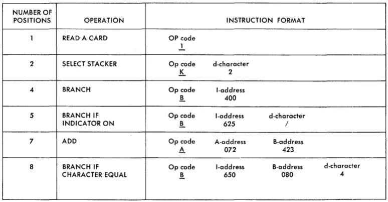
Instructicm Format
Op Code A- or I-address B-address
X
XXX
xxx
d-character XMnemonic. This is the mnemonic operation code used
by the SPS or Autocoder processor program(s) to
designate the actual machine operation code.
Op Code. This is always a single character that defines
the basic operation to be performed. A word mark
is always associated with the operation code
posi-tion of an instrucposi-tion.
A-Address. This always consists of three characters.
It
can identify the units position of the A-field, or it
can be used to select a special unit or feature (tape
unit, disk storage unit,
IBM1419 Magnetic
Char-acter Reader, etc.).
I-Address. Instructions that can cause program
branches use the I-address to specify the location
of the next instruction to be executed if a branch
occurs.
B-Address. This is a 3-character storage address that
identifies the B-field. I t usually addresses the units
position of the B-field, but in some operations (such
as tape read and write) it specifies the high-order
position of a record-storage area.
d-Character. The d-character is used to modify an
operation code.
It
is a single alphabetic, numerical,
or special character, positioned as the last character
of an instruction.
Instruction Descriptions
Specific instructions have been described in a standard
format:
Title. This is the description of the instruction.
Instruction Length. The length of an instruction can
be either 1, 2, 4, 5, 7, or 8 characters.
It
cannot be
either 3 or 6 characters long. Characters beyond the
usable limit of eight do not aHect the operation.
Addressing advances (mod·+ 1) until the next word
mark is sensed before the instruction is executed.
Most instructions must have a word mark
follow-ing the instruction in core storage. This word mark is
normally associated with the core-storage location
immediately following the instruction itself.
Figure A-6 shows examples of the combinations
possible in variable-length instructions.
Instruction Format. This is the format of the
particu-lar instruction described. The mnemonics operation
code used for Autocoder and SPS are given.
Function. This is the function of the instruction.
Word Marks. This is the effect of the word marks
with regard to data fields.
Timing. When the instruction-execution timing is
al-ways a constant, the actual time in milliseconds is
given. When the instruction-execution time can vary
because of field length or chaining, the formula is
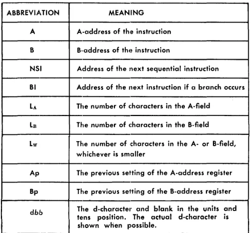
given. Figure A-7 is the key to the abbreviations
used in the formulas.
Notes. These are special notations or additional
infor-mation pertaining to the operation.
Address Registers After Operation. The contents of
the address registers are represented by the codes
described in Figure A-8.
e
haining. This assists the programmer in determining
whether instruction-chaining can be used effectively.
In some cases, chaining proves useful even though it
would not ordinarily be used. For example, another
instruction can be chained to the
MOVE CHARACfERS AND EDITinstruction
if
the programmer can use the
contents of the address registers to advantage. When
considering the use of chaining, be certain that the
contents of the address registers are valid for all
conditions relating to the instructions involved.
(Re-fer to the specific instruction section.)
NUMBER OF
Example. A practical application of the instruction is
described with the label of a typical actual machine
address (in parentheses).
These examples for the instructions are
representa-tive, and are intended as exhibits of typical
core-storage assignments, rather than specific, limited
ex-amples. Since the assembler program (autocoder or
SPS) is usually allowed to establish core-storage
addresses, the programmer need not ordinarily be
concerned with specific machine-language storage
locations, except when a program must be analyzed.
The few inflexible addresses of core-storage
loca-tions, such as index registers, are shown in the
in-structions as exact locations.
Assembled Instruction. This is the actual machine
language instruction that is assembled by the
proc-essor program from the symbolic entries shown in
the example.
When an explicit mnemonic is used, the op code,
A-address, and d-modifier (when required) are
auto-matically generated in most cases (refer to the
spe-cific operation in question).
Example: The coded instruction to cause
infor-mation to print on the 1447 might be in the form:
WCP (column 16 of the coding sheet), PRTOUT
(written in column 21-26). Assume for the purpose of
this example that the label PRTOUT actually
repre-sents core-storage location 0101. Autocoder would
assemble this coded instruction into actual machine
POSITIONS OPERATION INSTRUCTION FORMAT
1 READ A CARD OP code
.!.
2 SElECT STACKER Op code d-character
K.
24 BRANCH Op code I-address
!l 400
5 BRANCH IF Op code I-address d-character
INDICATOR ON !l 625 /
7 ADD Op code A-address B-address
h- 072 423
8 BRANCH IF Op code I-address B-address d-character
CHARACTER EQUAL !t 650 080 4
Figure A-6. IBM 1401 Instruction Formats
A-6
[image:10.613.43.430.509.710.2]Key to abbreviations used in formula: LA = Length of the A-field
Ln Length of the B-fleld Lc Length of multiplicand field L Length of argument field Lr Length of instruction
br Length of multiplier field LQ Length of quotient field LR
=
Length of divisor field Ls = Length of sectorLH = Number of significant digits in divisor (Excludes high-order O's cmd blanks) Lw
=
Length of A- or B-fleld, whichever is shorter Lx=
Number of characters to be clearedh
=
Number of characters back to right-most "0" in control fieldLz = Number of O's inserted in a field I/O
=
Timing for input or output cycleFill
=
Forms movement times. Allow 20 ms for first space, plus 5 ms for each additional spaceN = System processing cycle time (.0115 ms for 1401; .006 ms for 1460)
Ns
=
Number of sectors Ss = Size of sectors Till=
Tape movement times~
=
Number of fields included in an operation Figure A-7. Timing Formula CodingABBREVIATION MEANING A A-address of th'e instruction B B .. address of the instruction
NSI Address of the next sequential instruction BI Address of the next instruction if a branch occurs LA The number of characters in the A-field LB The number of c:haracters in the B-fleld Lw The number of characters in the A- or B-fleld,
whichever is smaller
Ap The previous setting of the A-address register Bp The previous setting of the B-address register
dbb The d-characte,· and blank in the units and
tens position. The actual d-character is shown when possible.
Figure A-8. Address Registers after Operation Coding
language as follows: M %TO 101 W. In this instance,
the machine-language op code (M), the A-address
designating the 1447 (% TO), and the d-modifier
character defining the operation as a write (W) were
all explicitly defined in the Autocoder mnemonic:
WCP.
Example: When an explicit Autocoder mnemonic
is
not
provided, or
if
the programmer uses a
«gen-eral" mnemonic, the A-address and the d-modifier
must
be written as part of the operand: MU
(col-umn 16-17), unit address %TO (starting in col(col-umn
21), B-address (starting next), and the specific
d-character W (last). In this case, the results are the
same: M %TO 101 W.
Example: The instruction can be coded entirely
in machine language, if desired. In this case, the
actual op code is written in column 19, and the
d-modifier character is written in column 20.
Example: In other cases, the actual machine
lan-guage op code is implied by the mnemonic, but the
d-modifier character must still be coded in the
operand, such as for the
BRANCH IF CHARACTER EQUAL(BCE) instruction. Here, the machine language op
code (B) is explicit, but the flexibility of the
d-character requires that the programmer code the
d-modifier.
Addressing
Instructions and data used for processing in the 1401
and the 1460 are kept in core storage. Each
core-storage position in the area has its own unique address.
The
IBM1401 Processing Unit is available in six
dif-ferent capacities of core storage: 1,400; 2,000; 4,000;
8,000; 12,000; and 16,000 positions.
The
IBM1441 Processing Unit for the 1460 system is
available in three different core-storage capacities:
8,000; 12,000; and 16,000 positions. Each position of
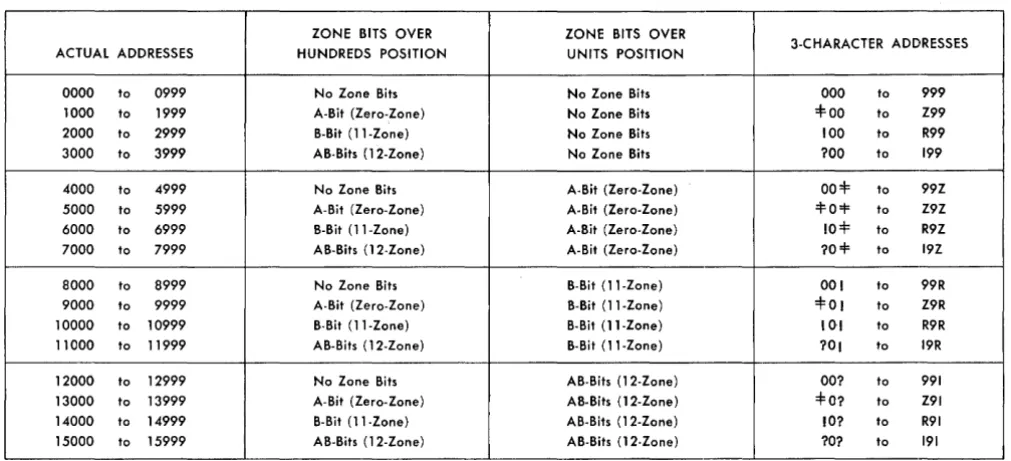
core storage is identified by a 3-digit address. To reflect
addresses over 999, zone bits are placed over the
hun-dreds and/or the units position of a 3-digit number in
various combinations.
Storage addresses 1000-3999 have zone bits over the
I
hundreds position, and no zone bits over the units
posi-tion of the 3-character address.
Storage addresses 4000-7999 have zone bits over the
hundreds position, and A-bits (0 zone) over the units
position of the 3-character address.
Storage addresses 8000-11999 have zone bits over
the hundreds position, and B-bits (11 zone) over the
units position of the 3-character address.
Storage addresses 12000-15999 have zone bits over
the hundreds position, A- and B-bits (12 zone) over
the units position of the 3-character address. Figure
A-9 is a chart of the addressing system.
[image:11.613.73.318.68.289.2] [image:11.613.75.320.341.568.2]ZONE BITS OVER ACTUAL ADDRESSES HUNDREDS POSITION
0000 to 0999 No Zone Bits 1000 to 1999 A-Bit (Zero-Zone) 2000 to 2999 B-Bit (11-Zone) 3000 to 3999 AB-Bits (12-Zone)
4000 to 4999 No Zone Bits 5000 to 5999 A-Bit (Zero-Zone) 6000 to 6999 B-Bit (11-Zone) 7000 to 7999 AB-Bits (12-Zone)
8000 to 8999 No Zone Bits 9000 to 9999 A-Bit (Zero-Zone) 10000 to 10999 B-Bit (11-Zone) 11000 to 11999 AB-Bits (12-Zone)
12000 to 12999 No Zone Bits 13000 to 13999 A-Bit (Zero-Zone) 14000 to 14999 B-Bit (11-Zone) 15000 to 15999 AB-Bits (12-Zone)
Figure A-9. Addressing System
The system addresses core-storage locations by
as-signing a digit value to each bit that appears over the
hundreds and units positions of the 3-character address.
Bit and Location
A-bit over hundreds position B-bit over hundreds position A-bit over units position B-bit over units position
Digit Value 1
2 4 8
The machine adds the assigned digit values of the
hundreds and units positions to determine the
thou-sand block of storage addressed.
A 1
?99
=
B 2 3099099 099
A 1
15R
=
B B 2 8 11,959959
959-Data-Field Addressing
A data field in core storage is addressed by specifying
the low-order (units) position of the field in the A- or
B-address of the instruction. The data field is read from
right to left until a word mark in the high-order
po-sition is sensed.
Instruction Addressing
An instruction in core storage is addressed by giving
the high-order (operation code) position of the
in-struction. All operation codes must have a word mark.
A-8
ZONE BITS OVER
3-CHARACTER ADDRESSES UNITS POSITION
No Zone Bits 000 to 999 No Zone Bits =1=00 to Z99 No Zone Bits 100 to R99 No Zone Bits ?OO to 199
A-Bit (Zero-Zone) 00=1= to 99Z A-Bit (Zero-Zone) =1=0=1= to Z9Z A-Bit (Zero-Zone) 10:f to R9Z A-Bit (Zero-Zone) ?o=l= to 19Z
B-Bit (11-Zone) 00 I to 99R B-Bit (ll-Zone) =1=01 to Z9R B-Bit (11-Zone) 101 to R9R B-Bit (ll-Zone) ?Ol to 19R
AB-Bits (12-Zone) OO? to 991 AB-Bits (12-Zone) =l=0? to Z91 AB-Bits (12-Zone) 10? to R91 AB-Bits (12-Zone) ?O? to 191
(This word mark is normally set by the load routine
when the instructions are loaded.) The machine reads
an instruction from left to right until it senses the word
mark associated with the next sequential instruction
(see item 7 under "Vord Marks for exceptions). The
final instruction in the program must have a word
mark set at the right of its low-order position.
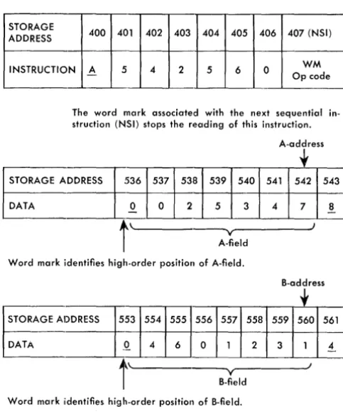
Example:
Instruction address 400 (Figure A-10)
con-tains the operation code for the following instruction:
Op Code
A
A-address
542
B-address
560
When this instruction is executed, the data in the
A-field is added to the data in the B-field.
0025347
04601231
04626578
The result is stored in the B-field.
Input-Output Storage Assignments
Three areas of storage are reserved for input and
out-put data. Storage positions 001 through 080, are
re-served for the information from the 80 columns of the
card. The second area of storage, positions 101 through
180, is reserved for assembling data to be punched.
Positions 000 and 100 should not be used. Data stored
in position 000 before a card-read operation is replaced
by CAB bits at the end of the read operation. Data
[image:12.615.44.550.77.308.2]Instruction addressed by high-order position
1 402 403 404 405 406 407 (NSI)
4 2 5 6 0 WM Op code STORAGE
n
oo 40ADDRESS
INSTRUCTION A 5
The word mark associated with the next sequential in-struction (NSI) stops the reading of this inin-struction.
A-address
f
536STORAGEA~
DATA
~
537 538 539 540 541 542 543
.Q. 0 2 5 3 4 7
!
t
\ . ' - - - y - - - l
A-field
Word mark identifies high-order position of A-field.
B-address
~
53 554 555 556 557 558 559 560 561Q. 4 6 0 1 2 3 1
.!
STORAGE ADDRESS
I'
DATA _
t
\ . ' - - - y - - - IB-field
Word mark iidentifies high-order position of B-field.
Figure A-lO. Data and Instruction Addressing
APPLICATION. _ _ _ _ _ _
'0001
,-
i",,,
,-
,»
,-
r .. ,oo''''101
1 __
1
I'"
,,,,
[iM
''''
I
-I''''
"
..
, "" I"" '''' "" "" "" '040""
-"
...
[i1iO
[,-J1iOO
"
...
- ( - - - -f---f--- - -
-,,,
..
"'"
pOOl ,
..
" I"" I,m I ....- - f.";--[mo- jm.--- p ...
Figure A-II. Core Storage Layout Chart
stored in position 100 before a punch operation is
re-placed by C82 bits at the end of the punch operation.
The third area of storage, positions 201 through 300
or 332, is reserved for assembling characters to be
printed. Positions 81 through 99, and 181 through 200,
are available for normal storage use. When the
re-served areas are not being used as specified, they can
be used for other storage operations (Figure A-II).
Address Modification
It becomes necessary in some 1401 and 1460 programs
to perform the same operations repetitively, with a
change only in the A- or B-address. Changing an
ad-dress while retaining the rest of the instruction is called
address modification.
Address modification can
de-crease the number of program steps and the number
of storage requirements. In some cases, the program
itself determines whether and how addresses are to be
changed in order to perform the correct program steps
for conditions that arise during the processing of data .
There are two basic methods of address
modifica-tion. The first method does not require the indexing
feature. The second method makes use of the
index-ing feature, which is a speciial feature for the 1401
and 1460 systems.
___________ DATE ______ _
r'i 180
,,,
..
..
+-
I" ,..
I" I"I ~---...
1180
,-
-291,
..
'"I'" '"
I'" '"
...
...
- - - ---f--- ---,,;
"
..
"..
---,,; --- - ---,.
I'" I"" I"" ,,,"
,_
I"" I'''' :,m ,OIO '01' i''''
"
...
,
...
,,,.
"'. - ( - - - I i t i
I"" i,~
1-- - -- - - -+-- ---.-..;
,
....
"'"
i .. ,[mo-- - -
-....
- - 1-- --"..
,,,.
- - - - ,-,o. "
..
I .... f"'O- jim jiKO ,
....
,,,"
rom-
I, ... I,·" ---UtO I,","ii
[image:13.618.69.311.88.380.2] [image:13.618.72.576.413.712.2]Address Modification Without Indexing
Address modification uses the A- and B-bit
accumula-tion that can occur in the hundreds and units posiaccumula-tions
of a field. This accumulation is discussed in connection
with overflow indication in the
Arithmetic Operations
section of this publication.
Using Modulus 4 Arithmetic
For 1401 systems of 4,000 storage positions or less,
A-and B-bit accumulation should occur only in the
hun-dreds position, and is based on modulus 4 arithmetic.
To understand how a modulus 4 arithmetic operation
is accomplished, let us assign digital values to the
A-and B-bit configurations:
No A, No B = 0
A
=
1B = 2
AB = 3
In a modulus 4 system, the highest digit is 3. Values
in excess of three are equal to that value minus four.
For example, 5 is a digit
l. In this system, only two
factors can be accumulated at a time (Figure A-12).
Digit values in the high-order position of a field
accumulate in the normal manner. In 1401 systems of
4,000 core-storage positions or less, it is assumed that
there is a word mark in the high-order position of the
address being modified.
Modification to a higher address in 000-999 address
range is:
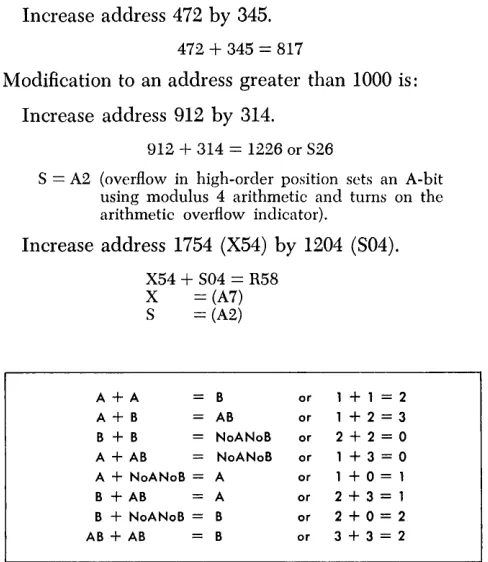
Increase address 472 by 345.
472
+
345 = 817Modification to an address greater than 1000 is:
Increase address 912 by 314.
912
+
314 = 1226 or S26S = A2 (overflow in high-order position sets an A-hit using modulus 4 arithmetic and turns on the arithmetic overflow indicator).
Increase address 1754 (X54) by 1204 (S04).
X54
+
S04=
R58X
=
(A7) S = (A2)A+A B or 1 + 1 = 2
A+B AB or 1+2=3
B + B NoANoB or 2+2=0 A + AB NoANoB or 1+3=0 A + NoANoB = A or 1+0=1
B + AB A or 2+3=1
B + NoANoB = B or 2+0=2 AB + AB B or 3 + 3 = 2 Figure A-12. A-Bit and B-Bit Values
A-IO
Using the rules of modulus 4 arithmetic, A
+
A = B-hit, the new address is:958 with a B-hit over the high-order position (B9 = R) or R58 (2958).
To decrease an address, a different means must be
used. Modulus 4 arithmetic operates for addition only.
Decreasing an address requires the addition of a
com-plement, rather than doing a conventional subtract
operation.
In 1401 systems of 4,000 core-storage positions or
less, the 16,000's complement of the decrement is added
to the address to be modified.
Decrease address 879 by 148.
16,000 - 148 == 15,852 (H5B) = complement 879
+
H5B = 731 (with arithmetic overflow) H=BA8B =BA2
U sing the modulus 16 rules, the arithmetic overflow
adds an A-bit in the hundreds position (the hundreds
position already contains A- and B-bits, and the units
position contains A- and B-bits, the combination of
which indicates a 15000 to 15999 block address). The
addition of the A-bit increases the value of the zone
bits to 16, which, according to modulus 16 rules has
a new address value of 0 (000-999 block address).
Therefore, the new address is 731, and the overflow
indicator is
ON.System Register Operation
The
IBM1401 and 1460 Data Processing Systems can
operate on and process data to produce a desired result
by executing a series of instructions at high speed. A
series of instructions designed to solve a problem is
known as a
program.
Because these instructions are
retained in core storage,
itis more properly called a
stored program.
The processing unit must interpret an instruction
and perform the function prescribcd by the instruction.
To do this, various devices are used that are capable
of receiving information, storing it, and transferring it
as directed by control circuits. These devices are known
as
registers.
The 1401 and 1460 have seven registers;
four are address registers and three are character
reg-isters (Figure A-13).
Address Registers
[image:14.612.43.287.424.705.2]"coco
LStom
g,~Data
~gister
A Data Register
Arithmetic and Logic Register
Op
Register
Notes: The STAR's (Storage Address Registers) address the instruction or data location of the operation.
The Aux (Auxiliary) STAR's are used only with the Multiply-Divide Special Feature. Figure A-13. System Data Flow Schematic
registers control the data transfer from one storage
location to another. The fourth register specifies which
storage location is active during a particular storage
cycle.
I-Address Register
The 1- (Instruction) address register always contains
the storage location of the next instruction character to
be used by the stored program. The number in this
register is increased by one as the instruction is read
from left to right.
A-Address Register
The A-address register normally contains the storage
address of the data in the A-address portion of an
in-struction. Normally, as the instruction is executed, the
number in this register is decreased by 1 after each
storage cycle that involves the A-address.
NOTE: If the A-address portion of the instruction does not contain a core-storage address (for example % Ux), the contents of the A·address register are not modified as previously ex-plained as the instruction is executed.
B-Address Register
This register normally contains the storage location of
the data in the B-address portion of an instruction.
Normally, as a storage cycle involving the B-address is
executed, the storage address in the B-address register
is decreased by l.
Storage-Address Register
The storage-address register always contains the
ad-dress of the core-storage position that was involved in
the last particular machine cycle.
IBM 1401 G A- and B-Address Registers
The
IBM1401G A- and B-address registers differ in use
from the 1401, because in the 1401G, the reader-punch
is controlled through the use of A-cycles rather than
B-cycles. As a result, the final A-storage-address
regis-ter and B-storage-address regisregis-ter differ from the 1401
as follows:
[image:15.617.78.411.79.334.2]1401 1401-G 1401 1401-G
A-Storage A-Storage B-Storage B-Storage
Address Address Address Address
Operation Register Register Register Register
5 op Ap 181 or 081 181 or 081 Bp
6
op Ap 181 181335
7
op Ap 181 or 081 181 or 081335
1 op Ap 081 081 Bp
2 op Ap Ap
335
335
3
op Ap 081 081335
4
op Ap 181 181 BplXXX
BI 081 081 A4XXX
BI 181 181 A3XXX
BI 081 081335
5XXX
BI 181 or 081 181 or 081 A6XXX
. BI 181 181335
7XXX
BI 181 or 081 181 or 081335
6R
dbb 081 081335
4R
clbb 081 081 dbb6XXXR
BI 081 081335
4XXXR
BI 081 081 dbbCharacter Registers
The A- and B-character registers and the Op-register
are single-character registers used to store data during
the execution of an instruction.
Op Register
The Op- (Operation) register stores the operation
code of the instruction in process for the duration of
the operation. The operation code is stored in BCD
code including the check bit, but excluding the word
mark.
B-Register
Each character leaving core storage enters the
B-register. The character is stored in 8-bit form (BCD
code, check bit, and word mark). The B-register is
reset and filled with a character from core storage on
every storage cycle.
A-Register
The A-register is reset and filled with the character
from the B-register during each storage cycle that
in-volves the A-address, and during all instruction cycles
except the first and last 1- (Instruction) cycle of each
instruction. Data is stored in 8-bit form.
NOTE: Information can be written back into core storage directly from either the A- or B-register or from the Arith register.
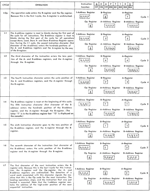
Figure A-14 shows the I-phase of an operation and
gives a detailed schematic for loading a 7-character
instruction in the operation code register, in the A- and
B-registers and in the 1-, A-, and B-address registers.
Eight storage cycles are required to load the complete
A-12
mstructIOn in the register. Each 1401 storage cycle
requires .0115 millisecond, and each 1460 storage cycle
requires .006 millisecond.
NOTE: The A- and B-address registers contain ,3-character addresses. Actual addresses are shown in this schematic because the storage display lights on the console show 4-digit addresses.
Chaining Instructions
In some programs, it becomes possible to perform a
series of operations on severa1fields that are in
con-secutive storage locations. Some of the basic
opera-tions, such as
ADD, SUBTRACT, MOVE,and
LOAD,have the
ability to be
chained
so that less time is required to
perform the operations, and space is saved in storing
instructions. Here is an example of the chaining
tech-nique: assume that four 5-position fields stored in
sequence are to be added to four other sequential
fields. This operation could be done using four
7-character instructions:
A
700
850
A
695
845
A.
690
840
A
685
835
At the completion of the first instruction, the
A-address register contains 695, and the B-A-address
regis-ter contains 845. These are the s'ame numbers that are
in the A- and B-addresses in the second instruction.
Eighty storage cycles would be required to execute
these instructions, thus using up .920 millisecond (1401
time). Also, 28 storage positions are required to store
these instructions.
By taking advantage of the fact that the A- and
B-address registers contain the necessary information to
perform the next instruction, this same sequence of
operations can be executed as follows:
A
700
850
A
A
A
Connecting instructions together in this manner is
called
chaining.
The first add instruction contains both
the A- and B-addresses. The following three
instruc-tions contain only the operation code for those
in-structions. The A- and B-addresses are the results left
in the A- and B-address registers from the previous
instruction. This type of operation requires 62 storage
cycles and takes .713 ms (1401 time) to execute.
Stor-age of these chained instructions requires only ten
storage positions.
The ability to chain a series of instructions does not
depend on the use of the same operation code" Chained
CYCLE OPERATION
I-Op The operation code enters the B-register and the Op register.
1-1
1-2
1-3
1-4
1-5
1-6
1-7
Because this is the first I-cycle, the A-register is undisturbed.
rhe A-address register is reset to blanks during the first part of the cycle for all instructions. The B-address register is reset to blanks during the first part of the cycle for all operations E!XCept Move, Load, Store A- and Store B-address Register opera-tion. During the 1-1 cycle, the second instruction character (first character of the A-address) enters the hundreds positions of I the A- and B-address registers and the A-register by the way of the B-regisler.
The third character of the instruction enters the tens posi-Ition of the A- and B-address registers, and the A-register through the B-register.
The fourth instruction character enters the units position of the A- and B-address registers, and the A-register through the B-register.
The B-address register is reset at the beginning of this cycle. The fifth instruction character (first character of the B-address) enters the hundreds position of the B-address register, and the A-register through the B-register. (The letter "T" is in the B-address register but "13" is displayed on the console.)
The sixth instruction character goes to the tens position of the address register, and the A-register through the B-register.
The seventh character of the instruction (last character of the B-address) enters the units position of the B-address register and the A-register through the B-register.
The first character of the next instruction enters the B-rE!gister only. Because this is the last I-cycle for this instruc-tion, the A-register and the Op register, the A- and B··address registers are undisturbed. The detection of a word mark associated with this character signals the ma-chine that this is the Op code for the next instruction. The loading operations stops, and the instruction that was just loaded is executed. Note that the I-address register con-toins the address of the high-order position of the next sequential instruction.
Figure A-l4. Schematic of Instruction Loading
Instruction
I
AI
5I
6 1 7 1 T 1 1I
2I
s
I
Location 11971198119912001201120212031204 1 I-Address Register B-Register A-Register10111917 1
W
GJ
Cycle 1Op Register A-Address Register B-Address Register
I?,? I? I?
I
I
? I?I? I?I
I-Address Register B-Register A-Register
101119181
~
o
Cycle 2Op Register A-Address Register B- Address Register
W
[¥JbLbl
~blhl
I-Address Register B-Register A-Register
10,119191
GJ
GJ
Cycle 3Op Register A-Address Register B-Address Register
W
1015161b!
1 015161 b 1I-Address Register B- Register A-Register
I
°121 °1°I
[2J
G
Cycle 4Op Register A-Address Register B-Address Register
W
I 01516171I
°1516i
7I
I-Address Register B-Register A-Register
[j&LiJ
I2J
Cycle 5Op Register A-Address Register B-Address Register
1 °1516171 11131 bl b
I
I-Address Register B-Register A-Register101210121
GJ
Cycle 6Op Register A-Address Register B-Address Register
I 01516171
I
11 31 11 blI-Address Register B-Register A-Register
1 °121°1 3 I
[2J
0
Cycle 7Op Register A-Address Register B-Address Register 1°151617 1 11 ,3 11 12
I
I-Address Register B-Register A-Register
10 ,2 ,0 141
0
Cycle 8Op Register A-Address Register B-Address Register
W
101516171 11131112 I [image:17.615.76.573.79.710.2]instructions may have various Op codes. To be
oper-ated on, the A-fields must be in sequence, and the
B-fields must be in sequence. Example:
A
900
850
M
A
M
For example, assume that the data fields are each ten
characters long:
The ten characters at location 900 were added to 850. The ten characters at location 890 were moved to 840. The ten characters at location 880 were added to 830. The ten characters at location 870 were movcd to 820.
The description of each instruction includes the
con-tents of the address registers after the operation has
been performed. Figure A-8 shows the abbreviations
that indicate the contents of these registers.
By using this information, the programmer can
de-termine the status of the registers and decide whether
chaining is practical in specific cases.
A-14
NOTE: Instructions that do not contain core-storage addresses cannot be chained. For example,
M
% Ux xxx R is a tape read instruction. The tape unit is signaled as the machine reads the instruction. Although the A-address register contains %4x after the operation, chaining is impossible because the machine does not select the unit from the contents of the A-address register.Most single-address instructions (Op code and an
A-address) cause the A-address to be inserted in both
the A- and B-address registers (for example A xxx).
However,
MOVE, LOAD,and
STORE B-ADDRESS REGISTER(Op codes M, L, and H) do not disturb the B-address
register, and permit the programmer to use the
previ-ous contents of that register as part of the instruction.
All no-address instructions (Op code only) use the
previous contents of the A- and B-address registers
(if
applicable).
The contents of the B-address register after a branch
instruction (Op code and I -address) depend on whether
or not the indexing feature is installed.
1.
With the indexing feature installed, the B-address
register contains the address of the next sequential
instruction
if
a branch occurs.
.
2. Without the indexing feature installed, the
B-ad-dress register is cleared to blanks whenever a branch
occurs.
The operations performed by an
IBM1401 or 1460 Data
Processing System can be arranged into these general
classifi.cations:
1. Arithmetic operations
2.
Logic operations
3.
Data moving operations
4.
Miscellaneous operations
5.
Edit operations
6.
Input-output operations
Arithmetic Operations
The 1401 and 1460 perform the arithmetic operations
of the system by executing the instructions associated
with these operations. Adding, subtracting, and
pro-grammed multiply and divide operations make use of
these arithmetic instructions.
Logic Operations
The 1401 and 1400 programs test for certain
condi-tions that arise during processing, and transfer the
pro-gram to a predetermined set of instructions or
sub-routines, as a result of specific tests. The operations
that perform the testing are called
conditional branch
operations.
System Operations
Data-Moving Operations
The 1401 and 1460 data moving operations are used
to manipulate data within core storage during
process-ing. Depending on the specific operation, one
charac-ter, a group of characters or a part of one character
can be involved in the operation.
Miscellaneous Operations
The miscellaneous operations in the 1401 and 1460
in-volve clearing core storage, inserting and removing of
word marks from specific core-storage locations,
pro-grammed halt operations and other similar operations.
Edit Operations
The 1401 and 1460 editing operation can automatically
insert all desired commas, decimals, dollar signs,
aster-isks' credit symbols, and minus signs in a numerical
output field. In addition, unwanted zeros to the left of
a significant digit can be suppressed.
Input-Output Operations
The 1401 and 1460 stored programs control the data
transfer to and from the various attached input-output
units. Also, various unit operations are initiated by the
stored program.
Arithmetic Operations
The
IBM1401 and 1460 Data Processing Systems add,
subtract, multiply, and divide by applying the
add-to-storage
method of operation. The two factors to be
combined are added within core storage without the
use of special accumulators or counters. Because any
storage area can be used as an accumulator field, the
capacity for performing arithmetic functions; is not
limited by standard-size accumulators or by a
prede-termined number of accumulators within the system.
Also, programming steps can be saved because some
SIGN BCD CODE BIT CONFIGURATION Plus No A- or B-Bit plus A- and B-Bits Minus B-Bit Only
Plus A-Bit Only Figure B-l. Sign Bit Equivalents
TYPE
A-FLO. B-FLD. TYPE OF ADD OF
SIGN SIGN CYCLE OPER.
CARD CODE CONFIGURATION
No Zone 12 Zone 11 Zone OZone
SIGN OF RESULT
f - - -
--c--+
True Add+
+
A
-
Compl. Add Sign of Field0+
with LargerD
+
Compl. Add Magnitude-- True Add
-t - - - . - - -
~-S
-True Add
-U
+
B
+
Compl. Add Sign of Field T - -_._--- with Larger
R
-Compl. Add Magnitude
A - 1 - - - -
-C
+
True Add
+
T- - - ~---- - - -...
_-Figure B-2. Types of Add Cycles and Sign of Result for Add and Subtract Operations
Sign - Bits of A - Field
Sign-Bits of B-Field A B AB
A When: A
>
B A AB AB0 Resultant Sign
0 When: A
S
B A B ABS When: A
>
B B B B BU Resultant Sign
B When: A~B AB AB B AB
Figure B-3. Zone-Bit Table for Add and Subtract Operations
B-2
A
B
AB
arithmetic operations require that only one field be
transferred. In arithmetic operations, the 1401 and 1460
systems consider blanks and zeros the same. An
un-signed field is considered positive by the system.
Figure B-1 shows the four possible combinations of
zone bits and the values of the signs they represent.
The standard machine method of signing a field is to
indicate a positive factor with A- and B-bits (12 zone)
or No A- or B-bits (No zone), and to indicate a
nega-tive factor with a B-bit (11 zone).
The arithmetic operations in the
IBM1401 and 1460
Data Processing Systems are performed by using one
of two types of add cycles incorporated in the system.
The two types of add cycles are:
l.
true add
2. complement add
The type of add cycle performed depends on the
arithmetic operation and the signs and values of the
two factors involved (Figure B-2). All arithmetic
op-erations are performed with algebraic sign control. The
sign of a result depends on the operation, the
magni-tudes of the terms to be combined, and the sign-bits
of these terms.
Because all arithmetic operations are performed with
algebraic sign control, the
sign
of the result depends
both on the operation, and on the magnitude and signs
of the factors involved (Figure B-3).
True
Add
A true-add cycle is specified when the total number of
minus signs is an even number (0 or 2). The signs
con-sidered are the signs of the factors and the sign of the
operation.
The sign of the result after a true-add cycle carries
the original sign of the B-field when either an add or
a subtract operation is performed (Figure B-4).
A A A B B B B AB AB AB AB
- - -
t----A B AB A B AB A B AB
A AB AB B B B B A AB AB
A B AB AS AB B AB A B AB
B B B A AB AB B B B B
(+ B) + (+ A)
=
+ RFIELD B FIELD A
0065 + 0017 +
0 0 1 7 - - - 1
Result 0082 +
-
-
-
-
-
-
-(- B) + -(- A)
= -
RFIELD B FIELD A
0016 -
0009-0 0009-0 0009-0 9 - - - 1
Result
00'25
--
-
-
-(- B) - (-i-A)
= -
RFIELD B FIELD A
0025 - 0011 +
0 0 1 1 - 1
Result
0036--
--
-
- --(+ B) - (-A)
=
+ RFIELD B FIELD A
0036 + 0062
-0 -0 6 2 -
---I
Result 0098 +- - -
- -
- --
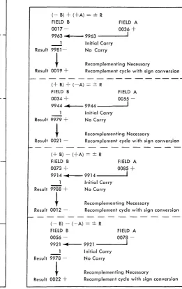
-(- B) + (+A)
=
± RFIELD B FIELD A
0036 - 0017 -~
9982
~-
9982 - - - ' Result 0019-Initial Carry Carry
-(Recomplementing Unnecessary) (+B) + (-A)
=
± RFIELD B FIELD A
0055
+
0034-9965 ~-9965 - - - - ' Result 0021
+
Initial Carry Carry
(Recomplementing Unnecessary)
----~---(+ B) - (+A) = ± R
FIELD B FIELD A
0085
+
0073+
9926 ~-9926 _ _
--.J
Initial Carry Result 0012+
Carry(Recomplementing Unnecessary) ( - B) - (-A) = ± R
FIELD B FIELD A
0078 -
0056-9943
~-
9943 - - - -... 1 Initial Carry Result 0022 - Carry(Recomplementing Unnecessary) Figure B-4. True-Add and Complement-Add Cycle
Examples
-Complement Add
An uneven number of minus signs (lor 3) specifies a
complement-add cycle. The system converts the
A-field factor to its nines complement figure and adds
it to the B-field factor (plus one initial carry). The
system then initiates a carry test to determine whether
a carry occurred from the high-order position of the
B-field. The presence of a carry indicates that the
result in the B-field is a true figure (Figure B-4). The
original sign of the B-field is the sign of the result.
If
there was no carry from the high-order position
of th