Systems Reference Library
Disk Storage Input/Output Instructions
IBM 1401 Data ·Processing System
IBM 1460 Data Processing System
This publication contains a description of the instructions used by the IBM 1401 and 1460 Data Processing Systems to operate the disk-storage units attached. The instructions and timing information for the following disk-storage units are included in this publication:
IBM 1405 Disk Storage IBM 1311 Disk Storage Drive IBM 1301 Disk Storage
For a list of other publications and abstracts, see the
IBM 1401 and 1460 Bibliography, Form A24-1495.
Preface
This publication is a portion of the reference text for the IBM 1401 and 1460 Data Processing Systems. The full set of manuals provides a detailed explanation of all the instructions used by the system to manipulate data. Detailed explanations of the instructions used with the required and available input/output units at-tached to the system are also included. The reader should be familiar with the IBM 1401 System
Sum-mary, Form A24-1401, or the IBM 1460 System Sum··
mary, Form A24-1496, and the various publications on
programming material, such as Symbolic Programming System (SPS) and Autocoder.
The complete manual is divided functionally into these sections:
System Operation Reference Manual (A24-3067) Section A
Section B Section C Section D Section E Section
J
Section KIntroduction System Operations IBM 1406 Operations IBM 1447 Operations
IBM 1402 and 1403 Operations Index of Instructions
Consolidated Index
Minor Revision, November 1964
This publication, A24-3070-2, is a minor revision of A24-3070-1.
It does not, however, obsolete the previous publication. The only change in this revision is the removal of all the IBM 1440 Data Processing System references and timings.
Tape Input/Output Instructions (A24-3069) Section F Tape Input/Output Operations Disk Input/Output Instructions (A24-3070)
Section G Disk Input/Output Operations Miscellaneous Input/Output Instructions (A24-3068)
Section H Miscellaneous Input/Output Oper-ations
Special Feature Instructions (A24-3071) Section I Special Feature Operations
The sections are independent and do not have to be used in the order in which they appear. A System Reference Library can be compiled using those sec-tions applicable to the user's machine configuration.
This publication is intended for programmers and systems personnel who have a general knowledge of the IBM 1401 or 1460 Data Processing Systems and who require a reference text for detailed information.
Other publications referenced here are, in most cases, prerequisites for a complete understanding of the material presented in this publication.
Copies of this and other IBM publications can be obtained through IBM Branch Offices.
Address comments concerning the content of this publication to IBM Product Publications, Endicott, New York 13764.
Reprinted March 1966
© 1960, 1961, 1962, and 1963 by International Business Machines Corporation
Contents
IBM 1405 Disk Storage ... ~ .. "... ... G-l
1405 Operation ... 0-1 1405 Instruction Format ... G-l 1405 Instructions ... G-2
IBM 1405 Disk Storage Timing ... G-6 IBM 1405 Error Routines ... G-6
Disk-Read Error Routines ... ... ... ... ... G-7 Disk-Write Error Routines ... 0-8
IBM 1311 Disk Storage Drive ... G-I0
Disk Control Field ... G-I0 Basic Disk Operations ... G-ll 1311 Instruction Format ... G-12 1311 Instructions ... G-12 1311 Sector Operations ... G-14 1311 Address Operations ... 0-20
IBM 1311 Disk Storage Timing ... G-23
IBM 1311 Error Routine G-25
IBM 1301 Disk Storage,
Models 11, 12, 21, and 22 ... G-27
Disk Control Field ... G-27 Basic Disk Operations ... "... G-28 1301 Instruction Format ... G-29 1301 Instructions ... G-30 1301 Sector Operations ... 0-30 1301 Address Operations ... G-35
IBM 1405 Disk Storage
J
405 Operation
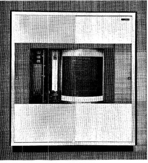
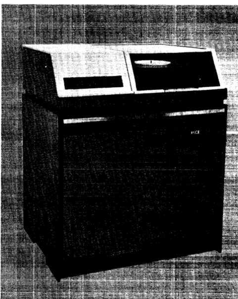
The mM 1405 Disk Storage unit (Figure G-1) pro-vides another medium of input-output for the mM 1401. This unit is available in two models: Modell, with a storage capacity of 10 million alphameric char-acters, and Model 2, with a storage capacity of 20 million characters.
Data Flow
The information is stored on the disks, which are di-vided into tracks and sectors so that the information can be located by the addressing scheme for reading and writing, during an input-output operation.
[image:5.612.77.315.451.712.2]The disk-storage operation is directed by outside control from the stored program in the mM 1401 Proc-essing Unit.
Figure G-1. IBM 1405 Disk Storage
Disk Input-Output Operations
J
405 Instruction
formatMnemonic Op Code A-address B-address d-chamcter
x M or
.b
%Fx xxx R or WOp Code
This is always a single character that defines the basic operation to be performed.
A·Address
%Fx
always appears in the (A) portion of a 1401 disk-storage instruction. The%F
signals that the disk unit is to be selected and the x represents the digit used to perform various operations:X-Position Opemtion
o
Seek a disk record.1 Single Record·-Reading or writing of 200
characters is stopped when a group-mark with a word-mark, or the end of a sector, is sensed. If a group-mark with a word-mark is sensed before completing the reading of the sector of the track, reading stops and the wrong-length record indicator turns ON.
2 Full track-An entire track is read or
writ-ten (5 sectors of 200 characters each). Read-ing or writRead-ing of the full track begins at the sector addressed and continues for four addi-tional sectors. If a group-mark with word-mark is sensed before compleing the reading of the last sector of the track, reading stops and wrong-length record indicator turns ON.
3 ·Write check-Data written on a disk in a
preceding write operation is read from the disk and compared, character-by-character, with the data in core storage. A WRITE CHECK
can be given following a single record or full-track operation.
B·Address
The B-address specifies the high-order position in core storage of the 8-digit record address. The record ad-dress must be followed by a group-mark with a word-mark and the area of core storage from which data is to be read into, or out of, by the disk-storage unit. The data area must be followed by a group-mark with a word-mark.
d·Character
The d-character is used to specify the operation to be performed.
G-l
1405 Instructions
Seek Disk
Instruction Format.
Mnemonic Op Code A-address B-address d-character
SPS MU or LU M or.h %FO xxx R
A SD
Function. The A-address specifies that a seek
opera-tion is to be performed by the access arm. The B-address specifies the high-order position in core storage of the disk-record address, which is followed by a group-mark with a word-mark.
The selected access arm seeks the disk and track specified in the disk-record address. Processing can continue while the access arm is in motion.
Word Marks. Word marks are not affected.
Timing. T
=
.0115 (LI+
9) ms+
access time.Note: If the access arm is already at the disk track that is to be
used, a SEEK DISK instruction need not be given.
Address Registers After Operation.
I-Add. Reg. A-Add. Reg. B-Add. Reg.
NSI B+1 B+8
Example. Seek record 050090 with access arm 1.
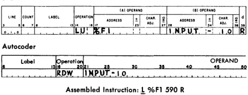
Stor-age location 0590-0597 (labeled INPUT A) contain 10500900 (Figure G-2).
Autocoder
Label
.
:Assembled Instruction: ~ Figure G-2. Seek Disk
Read Disk Single-Record Read Disk Full-Track
Instruction Format.
OPERAND
~!I
:~
~
%FO 590 R
Mnemonic Op Code A-address B-address d-character
SPS MU M %Fx xxx R
A RD (single record) RDT (full track)
G-2
Function. This instruction causes data to be read from
disk storage into core storage. The digit 1 in the A-address (%F 1) specifies that a single record is to be read. The reading of the disk is stopped by a group-mark with a word-mark in core storage and the end of the sector. If the digit 2 is present in the A-address (%F 2), a full-track read occurs. That is, five 200- character records are read from disk stor-age into core storstor-age. Reading stops at the end of the fifth sector.
The B-address specifies the ,high-order position in core storage of the disk-record address, which is fol-lowed by a group-mark with a word-mark, and the area in storage reserved for the data read from the disk.
The R in the d-character position signifies that this is a read operation.
Word Marks. A group-mark with a word-mark must
appear one position to the right of the record ad-dress and one position to the right of the last posi-tion reserved in core storage for the disk record. If
a group-mark with a word-mark is detected before reading of the record is completed, the wrong-length record indicator turns ON and reading stops.
Timing.
T
=
.0115 (LI+
9)+
10 ms+
disk rotation.60.196 ms is maximum time for a single-record read. 10.196 ms is minimum time for a single-record read.
N ate: Before reading starts, an automatic comparison of the
record address in storage with the record address on the disk is made. If they are not the same, the unequal-address com-pare indicator turns ON, and the data on the disk cannot be
read into storage.
Address Registers After Operation.
I-Add. Reg. A-Adel. Reg.
NSI B+1
B-Add. RtJg,
B+21O
or B + 1010
Example. Read a single record from disk storage to
core storage, beginning at location 0599 (area is la-beled INPUT A ). The disk-record address is located in the first eight positions of the nine positions pre-ceding the label (0590-0597), Figure G-3.
Autocoder
~
Label OPERAND:~
:
Assembled Instruction: M %Fl 590 RFigure G-3. Read Disk Single-Record
Read Disk Single-Record wHh Word Marks Read Disk Full-Track with Word Marks
Instruction Format.
Mnemonic Op Code A-address B-address d-charactcr
SPS LU L %Fx xxx R
A RDW (single record) RDTW (full track)
Function. These instructions are similar to the READ DISK SINGLE-RECORD and READ DISK FULL-TRACK in-structions except that word marks in the record area. of core storage are removed, and word marks from the disk records are written in core storage. The length of the record read into core storage from disk storage is 176 positions for a single record, and 880 positions for a full track.
Word Marks. A group-mark with a word-mark in core storage terminates the read operation. If the group-mark with a word-group-mark is not in the position to the right of the last character read from the disk into core storage, the wrong-length record indicator turns ON. A group-mark with a word-mark must be one position to the right of the record address.
Timing. T
=
.0115 (Lr+
9) ms+
10ms+
disk rotationNote: If a disk is read in a mode different from the one in which
it was written (M or 1 operation code) a parity error occurs. The read-parity check indicator turns ON.
Address Registers After Operation.
I-Add. Reg. A-Add. Reg. B-Add. Reg.
NSI B+1 B
+
186or B +890
Example. Read a record from disk storage, with its associated word marks, into the area labeled INPUT (first position of data is at 0599). The disk-record address is located in the first eight positions of the nine positions preceding the label ( 0590-0597), Figure G-4.
Assembled Instrl.ldion:!. %Fl 590 R
Figure G-4. Read Disk Single-Record with Word Marks
Write Disk Single-Record Write Disk Full-Track
Instruction Format.
Mnemonic Op Code A-address B-address d-character
SPS MU M
A WD (single record) vVDT (full track)
%Fx xxx W
Function. This' instruction causes a single record (or full-track characters) in core storage to be written on a disk record. The digit 1 in the A-address (%F 1)
specifies that a single record is to be written. If a 2 is present in the A-address (%F2) , five 200-char-acter records are written on a disk track. Writing stops at the end of the fifth sector.
The B-address specifies the high-order position of the disk-record address and is followed by the data to be written on the disk.
The W in the d-character position signifies that this is a write operation.
Word Marks. The writing of data stops when the end of a record is reached on the disk and a group-mark with a word-mark is sensed in core storage. If the group-mark with a word-mark is sensed before the end of a record, the remainder of the disk record is filled with data from core storage and the wrong-length record indicator turns ON. A group-mark with a word-mark must be one position to the right of the record address.
Timing.
T
=
.0115 (Lr+
9)+
10 ms+
rotation time. 60.196 ms is maximum time for single-record write. 10.196 ms is minimum time for a single-record write.Note: Before writing starts, an automatic comparison of the
record address in storage, with the record address on the disk, is made. If they are not the same the unequal-address com-pare indicator turns ON, and the data in storage cannot be written on the disk.
A WRITE DISK CHECK instruction must be performed follow-ing a write-disk operation. No other disk-storage operation can be performed until the check of data written on the disk is accomplished.
If the data in core storage contains characters with word marks, only the CBA 8421 portion of the character is written on the disk (the word mark is ignored).
Address Registers After Operation.
I-Add. Reg. A-Add. Reg. B-Add. Reg.
NSI B+1 B +210
or
B
+
1010Example. Write a disk record (single) from the data in area labeled INPUT A (first position of data is at 0599). The disk-record address is located in the first eight positions of the nine positions preceding the label (0590-0597), Figure G-5.
Autocoder
Label
.
:
Assembled Instruction: ~ %Fl 590 W
Figure G-5. Write Disk Single-Record
Write Disk Single-Record with Word Marks Write Disk Full-Track with Word Marks
Instruction Format.
Mnemonic Op Code A-address B-address d-character
SPS LU L %Fx xxx W
A vVDvV (single record)
WDTW (full track)
Function. This instruction is similar to the write disk
operation, except that word marks present in the data in core storage are recorded on the disk record. The mode of operation permits the writing of pro-grams on disk records for systems' use. One hundred and seventy-six positions of data with word marks are recorded on the disk during a write single-record operation, and 880 positions are recorded during a write full-track operation.
Word Marks. A group-mark with a word-mark one
position to the right of the last character of the rec-ord in core storage terminates the write operation.
If the group-mark with a word-mark is not in the correct position, the wrong-length record indicator turns ON. A group-mark with a word-mark must be one position to the right of the record address.
Timing. T
=
.0115 (LI+
9) ms+
10 ms+
disk rotation.N ate: The programmer should be certain that all records on a
specific track are written in the same mode (either by a
MOVE or by a LOAD instruction), otherwise, full-track opera-tions are not possible. A write-disk-check operation must be pedormed following this instruction.
Before writing starts, an automatic comparison of the record address in storage, with the record address on the disk, is made. If they are not the same, the unequal-address com-pare indicator turns ON, and the data in storage cannot be written on the disk.
Address Registers After Operation.
I-Add. Reg. A .. -Add. Reg. B-Add. Reg.
NSI B+1 B + 186
or B +890
Example. Write a disk record with word marks from
the area labeled OUTPUT (the first position of data
G-4
is 0599). The disk-record address is located in the first eight positions of the nine positions preceding the label (0590-0597), Figure G-6.
Autocoder
Label OPERAND
~!I 40
:~
:
.
:
Assembled Instruction:! %Fl 590 W
Figure G-6. Write Disk Single-Record with Word Marks
Write Disk Check
Instruction Format.
Mnemonic Op Code A-address B-address d-character
SPS MU M or
b
%F3 xxx WL U (word marks)
A WDC
WDCW (word marks)
Function. The function of this instruction is to cause
a comparison, character-by-character, of the data in core storage with the data just written on the disk. The system automatically reads the disk record that was the last record to be addressed by the 1401 pro-gram. This instruction must follow a write operation.
The digit 3 in the A-address specifies that a WRITE DISK CHECK is to be performed. Either a single record or a full track is checked, depending on how the data was recorded in disk storage.
The B-address specifies the area in core storage where the record address and data recorded on the disk are located.
Word Marks. A group-mark with a word-mark must
appear one position to the right of the disk-record address and of the disk data in core storage.
Timing. T
=
.0115 (LI+
9) ms+
50 ms.Note.' If the disk address in core storage is not the same as the
address on the record, the unequal-address compare indicator turns ON. If any of the characters on the disk record do not
agree with the characters in core storage, the read-back check-error indicator turns ON.
A WRITE DISK CHECK instruction can also follow a READ DISK SINGLE-RECORD instruction to verify data read from the disk.
The WRITE DISK CHECK and WRITE DISK CHECK WITH WORD MARKS instructions can have either an R or W specified as the d-character. A W d-modifier must be used for compatibility with the IBM 1410 Data Processing System.
If program compatibility with the IBM 1410 Data Process-ing System is necessary, the read check operation must be omitted.
Address Registers After Operation.
I-Add. Reg. A-Add. Reg. B-Add. Reg.
NSI B+l B +210
or B + 1010
Example. Compare the disk record with the record in the area labeled OUTPUT (first position of data is 0699). The disk-record address is located in the first eight positions of the nine positions preceding the label (0690-0697), Figure G-7.
Autocoder
-~---r---~ .~I~. OPERAND
~~'~~~~~U~I~M~I_~'.-~~~~'~~:O~.-.~~~~-.-~
Assembled Instruction:.!! %F3
Figure G-7. Write Disk Check
Branch if Indicator On
Instruction Format.
Mnemonic
SPS B
A BIN
Op Code
B
I-address
xxx
690 W
d-character
x
Function. The d-character specifies the indicator tested. If the indicator is ON, the next instruction is taken from the I-address. If the indicator is OFF, the next sequential instruction is taken. Figure G-8 shows symbols that are valid d-characters and the indicators they test.
The next disk-storage operation turns OFF the access-inoperable indicator. The other disk unit in-dicators are turned OFF by any disk operation except SEEK DISK.
Indicators: Access Inoperable-An access arm be-, comes inoperable if the logic safety circuit detects improper operation. A customer engineer can also render an arm inoperable. In either instance, this indicator turns ON when the program addresses the
d-CHARACTER INDICATOR
N Access Inoperable
V Read- or Write Parity Check or Read-Bclck Check Error
W Wrong-Length Record
X Unequal-Address Compare
y Any Disk-Unit Error Condition
Figure G-8. d-Character for BUANCH IF INDICATOR ON
Instruction
inoperable arm. At the same time, the appropriate access light (1405) and the RAMAC® light (1401) tum ON.
The indicator also turns on if an invalid (not in-stalled) arm or disk storage unit is addressed. Because the program continues in sequence, even when an inoperable arm is addressed, a BRANCH IF INDICATOR ON instruction should follO'w a seek instruction.
Read or Write Parity-Check or Read-Back Check Error-This indicator turns ON if even-bit parity occurs when reading the record address and infor-mation from, or writing informatiO'n on, a disk. An-other condition that turns the indicator ON is an unequal compare during a write-check operation.
Wrong-Length Record-This indicator turns ON if the number of characters read from, or written on, the disk record is not equal to 200 or 1,000 charac-ters (for M operation code) or 176 or 880 characters ( for
..1.
operation code).Unequal-Address C omparc-This indicator turns ON if an unequal condition occurs during the auto-matic comparison of the record address in storage with the record address on the disk. This is an auto-matic check and does not have to' be programmed.
This is the same internal circuitry that is used by the COMPARE instruction. Care should be taken in programming that a normal-compare operation and the address-compare operation do not interfere with the setting of the equal, low, and high compare in-dica tors set by a previous instruction.
Any-Disk-Unit Error Condition-This indicator turns ON if any of the other disk-storage indicators are ON. It can be tested by the program, and, if it is OFF, allows the program to proceed. If the indicator is ON, the other indicators should be checked to de-termine where corrective measures should be taken.
Word Marks. Word marks are not affected.
Timing.
Without indexing:
T
=
.0115 (Lr+
1) msWith indexing:
T = .0115 (Lr
+
2) ms.Note: After each disk-unit read or write operation, the program
must test for error indications to prevent processing of unusable data.
Address Registers After Operation.
I-Add. Reg. A-Add. Reg.
NSI BI
B-Add. Reg.
dbb
Example. At the completion of a disk-read operation, test the any-disk-unit error condition indicator. If it
is OFF, continue in the main program. If it is ON, branch to the routine labeled DISKER (0690) to determine the type of error condition. This tests all disk-unit indicators and branches to the error routine of the respective indicator that is on. The routines are labeled: ACINOP (0690), UNADCL (0695), WRLENR (0700), RWPARC (0705,) Figure G-9.
SPS
(AIOPERANO (81 OPERl~O
ADDRESS
I!
I CHAR. AODRESSIt
I CHAR, ~ d18 17 2~1 ADJ. 27 28 !~I AOJ. 31 3.
IR 0 J,s~~:. :_"' f- .. --L . .L L--'-~:.
:.L .. , '(
~"I--.1 __ ...J...J.---L_ ... ____ .1. .L_ I I ~----L:":~
It>, I.S K E,RIB. I A Co I N 0 P~ ___ -'-__ , -'-_-L..""-_U_-, __ ""-_ )-/i
I-"-'-''-'-''-}---L.-J-L-~-'----L_ ~~_~..LPi.L~-'O&.lL.: .. ,: __ .1. ~J_ t L _1_ J _L _1_ t ___ 1 - . 1 x
1-"-'-''-'-''-}---L.-J-L-~--,-",-+,,8....J WR ~ e. N R: :-'_-'---.L.._.Ll_-'--_-'--I-_~ ~'-'-"-l---'--+--'--'--'-'--,--+I~ &'-!-: --I!R.:ll''' W!!I.L!:.'P ~Ali..'I\:'u'C .... ':_l:--'--'-f- -'--'--L-'4+--,--,-)--)-1{
~~-,-l....L-'--'-'--'--.l-'--.L..L-'--'-'--'--L~!...' -,--<---L.L.-L-L-.-L I ! , I '...l-L L
-Autocoder
label ic>peratior OPERAND
6
. I."
'"
I 25 50 35 40 45 110i IS,I.N. Ib , 5 K e,R .•. v.
t>,.~,)(.£.R.: IP..I.N lAC I NOP, N
I
IR.I N lJNAOCL.t)(.
I
ISI.N, WRI..£"N.Rt W : B I.N, IIl,w P,A.R. e., '1/
I
Assembled Instruction: 480 .! 690 Y
690 ]. 740 N
695 ]. 790 X
700 ]. 890 W
705 B 990 V
Figure G-9. BHANCH IF INDICATOR ON Testing Routine
DISKS
50
25
400
TRACK-TO-TRACK MOTION TIME DIFFERENT DISKS
500 600
MILLISECONDS
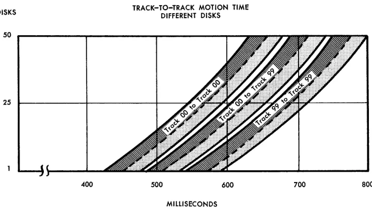
Figure G-lO. Track-to-Track Motion Time Different Disks
IBM 1405 Disk Storage Timing
Disk-Storage Access Time
To calculate timing for magnetic-disk operations, it is necessary to estimate the average time it takes to seek the records needed for a particular application. If
input to the operation is in sequence, the average access time is less than if the input data is unsorted. This can be explained by the fact that the duration of the seek depends on how far the access arm must travel.
To seek a track on another disk, the access arm moves horizontally, vertically, and horizontally again. The minimum time to move from the outside track of one disk to the outside track of an adjacent disk is 415 milliseconds. The maximum length of a seek oper-ation is from the inside track of the top disk to the inside track of the bottom disk and takes 800 milli-seconds. Figure G-10 shows track-to-track access times.
To seek a different track on the same disk (top or bottom face), the arm moves horizontally only. In this case, minimum seek time is 90 milliseconds and maxi-mum seek time is 250 milliseconds (Figure G-11).
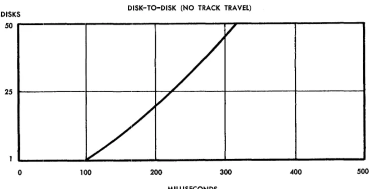
Disk-to-disk access time ranges from 100 to 315 milli-seconds. Figure G-12 shows timing for these opera-tions.
IBM 1405 Error Routines
Figures G-13 and G-14 show the correct sequence of error tests and branches that should be made after disk-read and/or disk-write operations on the mM
1405 Disk Storage unit. Failure to follow these se-quences can result in undetected errors and/or end-around check conditions.
700 800
[image:10.612.47.412.495.700.2]TRACKS
250
200
150
100
50
o 50
TRACK-TO-TRACK MOTION TIME SAME DISK
100 150
MILLISECONDS
Figure G-ll. Track-to-Track Motion Time Same Disks
DISK-To-DISK (NO TRACK TRAVEL) DISKS
I
200 250
50 r---~~---~~---~~---~---_,
25 ~---~---+-~~---~----.---+---~
o
100 200MlilLlSECONDS
Figure G-12. Disk-to-Disk Travel (No Track Travel)
300 400 500
Disk-Read Error Routines
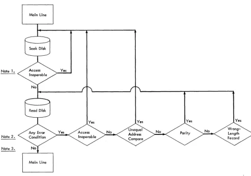
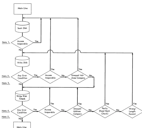
Figure G-13 shows the correct sequence of error tests and branches that should be made after a disk-read operation. Explanation of the notes in Figure G-13 follows:
[image:11.615.75.449.70.304.2] [image:11.615.70.441.358.548.2]Main Line
Note 1. Yes
Yes Note 2.
Note 3.
Main Line
Figure G-13. 113M 1405 Disk Read Error Routine
Note 1
Disk-Write Error Routines
Access-inoperable (or invalid-address) is the only error indicator that can be set during a seek operation. Because disk errors do not stop the program operation, this indicator should be tested after a SEEK and, if ON, the operation should be retried.
Note 2
The access-inoperable (or invalid-address) and un-equal-address compare indicators are set during the address phase of a disk-read operation. If either of these is ON, the operation ends and does' not enter the record phase. The program should branch back to the SEEK DISK instruction. The parity and wrong-length rec-ord indicators are set during the recrec-ord phase of a read operation. They should be tested and, if ON, the program should retry the read operation.
Note 3
Disk-read operations are normally retried three times before halting.
Figure G-14 shows the correct sequence of error tests and branches that should be made after a disk-write operation. Explanation of the notes in Figure G-14 follows.
Note 1
Access-inoperable (or invalid-address) is the only error indicator that can be set during a seek operation. Be-cause disk errors do not stop the program operation, this indicator should tested after a SEEK and, if ON, the operation should be retried.
Note 2
The access-inoperable (or invalid-address) and un-equal-address compare indicators are set during the address phase of a disk-write operation. If either of these errors occurs, the operation ends and does not enter the record phase. These indicators should be tested after a WRITE and, if ON, the program should branch back to the SEEK DISK instruction.
If neither the access-inoperable nor the unequal-ad-dress compare indicator is set ON, the operation enters the record phase and the write-check interlock is set. This requires that the next disk operation be a WRITE
[image:12.620.53.548.52.399.2]Note 1.
<
Note 2.
<
Note 3.
Note 4.
<
Note 5.
Seek Disk
Figure G-14. IBM 1405 Disk Write Error Routine
DISK CHECK. Although the parity and wrong-length rec-ord indicators can be set ON during a write operation, they are not tested before the WRITE DISK CHECK. If they were set ON by the WRITE, they will be set ON again by the WRITE DISK CHECK.
Note 3
Where possible, a processing loop is included between a WRITE and a WRITE DISK CHECK. If a programmed halt occurs in this loop and the start-reset key is pressed when restarting the program, all indicators are turned OFF. Therefore, the program should test the disk-error indicators before halting.
Note 4
If either the access inoperable or the unequal-address compare indicator is set ON during a write-disk-check operation, the operation ends and does not enter the record phase. The write-check interlock is still ON. This requires that the operation be retried.
Once the operation enters the record phase, the write-check interlock is turned OFF and, in the event of a parity (or readback check) or wrong-length record error, the program should branch back to the write instruction.
Note 5
Disk-write operations are normally retried three times before halting.
[image:13.612.63.557.61.504.2]IBM 1311 Disk Storage Drive
The IBM 1311 Disk Storage Drive (Figure G-15) pro-vides the 1401 and 1460 user with fast, efficient disk storage. As many as five IBM 1311 drives can be at-tached to a 1401 or 1460 system" and each drive is
equipped with an interchangeable disk pack capable of storing from 2 to 2.9 million alphameric characters. The first disk-storage drive attached to the 1401 system must be a 1311, Model 4; additional drives are 1311, Model 2.
The first disk-storage drive attached to the 1460 system must be a 1311, Modell; additional drives are 1311, Model 2.
Disk Control Field
A 10-digit disk-control field specifies the disk-storage area that is involved in the dat~ transfer. This disk-control field is located in core storage, and begins at the core-storage address specified by the disk-storage instruction B-address. The data involved in the trans-fer follows the disk-control field (no data area is re-quired for a seek-disk operation).
The various parts of the disk-control field are: alter-nate code, core sector address, and sector count (Fig-ure G-16).
Figure G-15. IBM 1311 Disk Storage Drive
G-10
Alternate Core-Sector Address
Sector Count Code
x xxxxxx xxx
* or
0-8 {even} 000000 - 099, 999 000 - 999
Figure G-16. Disk Control Field
Alternate Code
If an asterisk ('(t) is used in this position, the core sector addresses of the disk pack correspond to the address range for the disk drive on which the disk pack is placed.
A digit in the alternate-code position can be used to select the disk drive by the instruction. It allows drives with the same range of sector addresses to be used by the program during the same run.
When all disk drives have different sector addresses, an asterisk ('(t) instead of a numeric code can be placed
in the alternate-code position if the address range of the disk packs and disk drive are the same.
Both word marks and zone bits can be placed in the alternate code position. The word marks and zone bits do not affect the operation and are not lost.
Core-Sector Address
The core-sector address contains the 6-digit address of the first sector to be operated upon. Before any disk operation is performed, an automatic comparison is made of the sector address in core storage with the disk-sector addresses on the specific track. If an equal comparison is made, the operation continues. 1£ no equal comparison is made, the unequal-address com-pare indicator turns ON, and the disk operation is not performed.
When sector operations are performed, the core-sector address is automatically increased by 1 immedi-ately following the data transfer of each sector, except under these conditions:
1. track operation being performed
2. sector-count field reaches the value of 000 3. wrong-length record.
When any of these conditions occur, the core sector address is not increased by 1.
NOTES:
1. The high-order position of the 6-digit core sector address must contain a zero.
2. The other five positions of the 6-digit core sector address may contain any valid character that has a numeric-bit value of zero through nine.
[image:14.617.47.288.410.712.2]3. Zone bits over the core sector-address positions are lost if any address modification takes place.
4. Word marks over the core sector address positions will not affect the operation, but are lost during any operation per-formed in the load mode that involves address modification.
Sector COlunt
This field indicates the number of sectors to be oper-ated upon during the disk operation. The sector-count field is not used during seek operations. During the transfer of data to or from disk storage, the sector-count field is automatically decreased by 1 immedi-ately following a successful address comparison so that the sector-count field reflects the number of suc-cessful address comparisons.
If a sector count of 000 is used when initiating a disk-sector read or write operation, an error condition occurs. Before the first sector is transferred, a 1 is sub-tracted from the sector-count field. In this case, the result wQould be 999. Therefore, data would be trans-ferred until a group-mark with a word-mark is encoun-tered in core storage. Because the sectQor count is not zero at this time, the wrQong-length record and any-disk cQondition indicators would be turned ON.
NOTES:
l. Word marks cannot be placed over the sector-count field units position. Word marks in any other position do not affect the operation, but are lost during any operation performed in the load mode that affects sector-count modification. 2. Zone bits arc always removed from all three positions of
the sector-count field.
Basic
Disk Operations
The four basic operatiQons performed by the 1311 are seek, read, write, and write disk check.
Seek Operation
The seek operation is initiated by a SEEK DISK instruc-tion, which directs the read/write heads to' the proper cylinder on the disk pack. This instruction is followed by a read or write operation.
The data on the disk records is nQot acted on during this seek operation.
The seek operation positions the access arms over the specified cylinder. The B-address position of the in-struction contains the core-storage address of the disk-contrQoI field and it is this field that specifies the proper cylinder, plus other pertinent information.
Read OpE!ration
The read operation is initiated by one of the three dif-ferent types of READ DISK instructions, and transfers data from disk storage to a specified area in core stor-age. (The three types of instructions are discussed following the write-operation description.) The
speci-fied disk-stQorage area involved in the transfer is par-tially identified by the previQous seek operatiQon, and the rest of the area is fully identified before the data transfer takes place. The identification is accomplished by comparing the sector addresses on the disk with the sector address in core storage. The sector address in core storage is part of the disk-control field, and the B-address position of the READ DISK instruction con-tains the core-storage address of the disk-control field. The data from the disk is placed in a core-storage area located immediately to the right of the disk-cQonh'ol field.
Write Operation
The write operation is initiated by one of the three different types of WRITE DISK instructions, and transfers data from a specified core-storage area into disk stor-age. (The three types of instructions are discussed following this operation description.) The specific disk-storage area involved in the transfer is partially identified by the previous seek operation, and the rest of the area is fully identified before the data transfer takes place. The identification is accomplished by com-paring the sector addresses on the disk with the sector address in core storage. The sector address in core storage is part Qof the disk-contrQoI field, and the B-address portion of the WRITE DISK instruction contains the cQore-storage address of the disk-control field. The data that will be transferred to the disk is stored in a core-stQorage area located immediately to the right of the disk-contrQoI field.
Types of Read and Write Operations
Each read Qor write operation can operate in three dif-ferent ways, or modes: sector, track sectors with ad-dresses, and sector-overlay modes.
Sector Mode. Read and write operations in the sector mode transfer data, but do not transfer disk sector addresses. The sector mode is the normal mode of operation. The number Qof sectors to be handled dur-ing one operation is specified by the sector-count portion of the disk-control field. Each sector is trans-ferred only after a correct comparison Qof the sector address in the core-storage disk-control field is made with the sector address Qon the disk. For more de-tailed information, refer to the specific instruction.
Track Sectors with Addresses Alode. This mode of operation transfers both the data and the disk-sector addresses to and from the disk, one cQomplete track at a time. The mode of operation makes it possible to change the previously recorded sector addresses. The operation requires that the sector-address por-tiQon of the disk-control field contain the address of
one of the sectors within the specified track, and the sector-count portion of the disk-control field must contain 020 (20 sectors will be transferred). The transfer can only occur after a correct comparison of the sector address in the core-storage disk-con-trol field with a sector address on the specified track. For more detailed information, refer to the specific instruction.
Sector-Count Overlay Mode. This mode of operation allows a portion of the data record itself to specify the number of sectors that will be involved in the data transfer. The disk-sector addresses are not in-volved in the transfer. This mode of operation per-mits better disk storage utilization for sequential applications involving variable-size records. For more detailed information, refer to the specific in-struction.
Reading and Writing with Word Marks. Word marks can be transferred with the data during all reading and writing operations by an L Op code instead of an M Op code. When word marks are written on the disk, the data is written in an 8-bit BCD coding.
Write Disk Check
The write-disk-check operation causes the data in the specified disk area to be compared against the com-parable data in the specified core-storage area. When the disk data does not compare, bit-by-bit and charac-ter-by-character, with the core-storage data, a disk-error indicator is set ON. This operation normally takes the form of a WRITE DISK CHECK instruction, which must follow each write operation. The write-disk-check operation compares the data written in disk storage with the original source data in core storage.
1311 Instruction Format
Mnemonic Op Code
xx M/L
Op Code
A-address
%Fx
B-address d-chamcter
xxx R/W
This is always a single character that defines the basic operation to be performed. Either the M or L opera-tion code can be used with IBM 1311 instructions.
When the M Or-code is used, characters are written or read in 7 -bit mode (CBA 8421). The
1
Op-code causes characters to be read or written in 8-bit mode (CBA 8421 M). The 8-bit mode provides for a possible word mark with the character being written on, or read from, the disk record.A·Address
%Fx signals that the disk unit is to be selected; x rep-resents the digit used to perform various operations.
G-12
X-Position Operation
o Seek a disk record.
1 Sector-Reading or writing characters from the
number of sectors specified by the sector-count field is stopped when a group-mark with a word-mark or the end-of-sector is sensed. If a group-mark with
a word-mark is sensed before the reading of the sector(s) of the track is completed, reading stops and the wrong-length record and any-disk condition indicators turn ON. If the group-mark with a word-mark is sensed before the writing of a record on a disk is completed and it is before the end of a ree-o reI , the remainder of the disk record is filled with valid blanks (C-bit), and the any-disk condition and wrong-length record indicators are turned ON.
6 Disk Track-Sector with Addresses-Allows the
reading or writing of a full track (20 sectors) in-cluding sector addresses. To perform this operation, the write-address key-light on disk-storage unit 0 must be ON. When the write-address light is ON,
write-sector operations cannot be performed.
3 Write Disk-Check-Data written on a disk in a
preceding write operation is read from the disk and compared, character-by-character, with the data in core storage. A WRITE DISK CHECK must be given following a write operation, unless an error occurred
during the write operation.
A write-disk-cheek operation can be executed after a read operation if a check on the information read is desired. The operation is performed exactly the same as a write-disk-check operation following a write operation.
5 Sector-Count Overlay-Allows for records of a
variable number of sectors (more than one) to be read or written with a single instruction. The num-ber of sectors to be read/written is controlled by the multiple sector-count field. This control field is in the first three data positions of the first sector of the disk record. This technique permits better disk-storage utilization for sequential applications involv-ing variable-size records. The record itself specifies the number of sectors involved.
B·Address
The B-address specifies the high-order position in core storage of the 10-digit disk-control field. The disk-con-trol field is followed by the area of core storage that is to have data read into or out of by the disk-storage drive. The data area must be followed by a group-mark with a word-group-mark.
d·Character
The d-character is used to specify the operation to be performed.
1311 Instructions
Seek Disk
Instruction Format.
Mnemonic
SPS MU or LU
A SD
Op Code
M or L
A--address B-address d-character
%FO xxx R
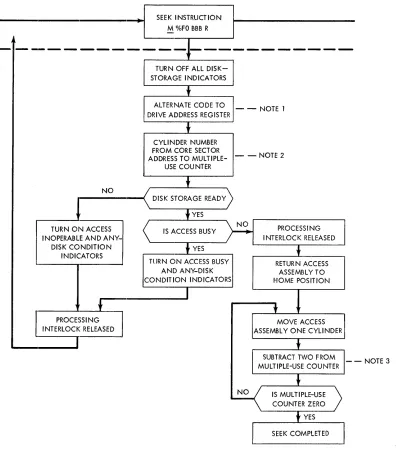
SEEK INSTRUCTION M %FO BBB R
- - NOTE 1
CYLINDER NUMBER FROM CORE SECTOR
ADDRESS TO MULTIPLE- - - NOTE 2
NO
TURN ON ACCESS INOPERABLE AND
ANY-DISK CONDITION INDICATORS
PROCESSING INTERLOCK RELEASED
USE COUNTER
TlJRN ON ACCESS BUSY AND ANY-DISK CONDITION INDICATORS
RETURN ACCESS ASSEMBLY TO HOME POSITION
Note 1. Drive address is taken from 8, 4, 2,-bits of second address digit, if alternate code position has B-bit.
Note 2. Cylinder number is taken from: a. l-bit of second address digit b. 8, 4, 2, l-bits of third address digit c. 8, 4, 2-bits of fourth address digit
Note 3. Subtracti()n does not take place when seeking to cylinder zero.
Figure G-17. Seek-Disk Functional Schematic
- - NOTE 3
[image:17.612.75.476.67.523.2]Function. The A-address specifies that a seek operation is to be performed by the access assembly. The B-address specifies the high-order position in core stor-age of at least the first six functions of the disk-control field. Only the alternate-code position and the first five positions of the core-sector address are used during a seek-disk operation.
The selected access assembly is first withdrawn from the disks to the home position, and then is moved toward the center of the disk pack. Move-ment of the mechanism stops when the sought track is reached.
Refer to Figure G-17 for a functional schematic of a seek-disk operation.
Word Marks. Word marks are not affected.
Timing. T
=
N~ (LI+
7) ms+
access time. 400 ms is maximum access time for a seek. 250 ms is average access time for a seek.o
ms if access mechanism is at track (SEEK DISK in-struction not given).<'tN = .0115 for 1401 or .006 for 1460
N ate: If the access mechanism is already at the disk track that
is to be used, a SEEK DISK instruction need not be given.
Address Registers After Operation.
I-Add. Reg. A-Add. Reg. B-Adcl. Reg.
NSI B+6 B+7
Example. Seek record 015734 with the access assembly. Storage locations 0590-0599 (labeled INPUTA) con-tains 0015734001 (Figure G-18).
SPS
Autocoder
Assembled Instruction: ~ %FO 590 R
Figure G-18. Seek Disk
1311
Sector Operations
If only the data portion of a disk record is to be af-fected, the operation is classified as a sector operation
(addresses are not affected). Disk records can be read, written, or scanned during sector operation. The term
sector operation does not mean that a disk record is confined to a 100-character sector. The data neededfor a record can be written in as many sectors as needed.
G-14
Read Disk Sector(s)
Instruction Format.
Mnemonic
SPS MU A RD
Op Code A-address B-address d-character
M %F1 xxx R
Function. This instruction causes data to be read from disk storage into core storage. The digit 1 in the A-address (%F1) specifies that a sector operation is to be performed. The number of sectors to be read is specified by the sector-count field. The reading of the disk is stopped by a group-mark with a word-mark in core storage and by the end of the sector.
Reading begins at the address contained in the core-sector address field and continues for the num-ber of sectors specified by the sector-count field.
The core-sector address field is increased by one for each sector read in excess of one, and the sector-count field is reduced by one as the sector is read.
When the sector-count field reaches 000, an end of operation is indicated to the system. An error condition results from any disk sector read or write operation that begins the operation with a sector count of 000. Before the first sector is transferred, a one (1) is subtracted from the sector-count field, resulting in a sector count of 999. Data would then be transferred until a group-mark with a word-mark is encountered in core storage. Because the sector count is not zero at this time, the wrong-length record and any-disk condition indicators are turned ON.
The B-address specifies the high-order position in core storage of the disk-control field, and the area in storage reserved for the data read from the disk.
The R in the d -character position signifies a read operation.
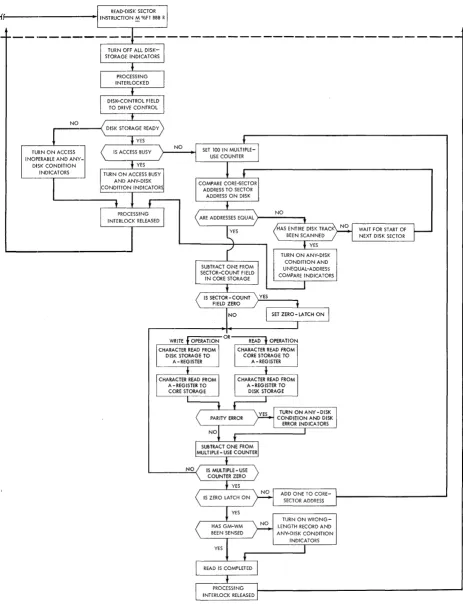
Refer to Figure G-19 fO'r a functional schematic of a read operation.
Word Marks. A group-mark with a word-mark must be one position to the right of the last position re-served in core storage for the disk record. If fl
group-mark with a word-mark is detected before reading of the record is completed, the wrong-length-record indicator turns ON and reading stops. The position of the group-mark with a word-mark can be determined by using the formula:
GM-WM
=
B+
Ns(Ls)+
10B
=
Address of high-order position of disk address in core storageNs
=
Number of s'ectors readLs
=
Number of characters per sectO'rTiming. T
=
N (LI+
1) ms+
2Ns+
disk rotation.~~~'---.---~
NO .~
C~)RAGE READY
YES
~
URN
ON ACCESSJ
INOPERABLE AND ANY-DISK CONDITION
INDICATORS
Figure C-19. Read/Write Disk Functional Schematic
[image:19.613.76.539.67.671.2]~44 ms is maximum time for disk rotation. 24 ms is average time for disk rotation.
4 ms is minimum time for disk rotation.
Note: Before reading starts, an automatic comparison is made
of the core-sector address with the sector address on the disk. This check is made for each sector reacl. If they are not the same, the unequal-address compare indicator turns ON, and
the data on the disk cannot be read into storage.
Address Registers After Operation.
I-Add. Reg. A-Add. Reg. B-Add. Reg.
NSI B+6 B
+
11+ NRLR
Example. Read one sector from disk storage into core storage beginning at location 0600 (labeled INPUT A). The disk-control field is located in the ten positions preceding the label (0590-0599), Fig-ure G-20.
SPS
Autocoder
I'
ISle~perati~
21 5 30 R D INPt";r.,,- 1.0
label OPERAND
~o
315 40 45
.
:Assembled Instruction:
M.
%Fl 590 RFigure G-20. Read Disk Sector
Read Disk Sector(s) with Word Marks
Instruction Format.
Mnemonic
SPS LV
A RDW
Op Code
L
A-address
%Fl
B-address d-character
xxx R
Function. This is similar to the READ DISK SECTOR in-struction except that (1) word marks in the record area of core storage are removed, and ( 2 ) word marks from the disk record are written in core stor-age. The length of the sector read from disk storage into core storage is 90 positions.
Word Marks. A group-mark with a word-mark in core storage terminates the read operation. If the group-mark with a word-group-mark is not in the position to the right of the last character read from the disk into core storage, the wrong-length-record and any-disk condition indicators turn ON.
Timing. T = N (LI + 1) ms
+
2Ns+
disk rotation. I)~ 44 ms is maximum time for disk rotation. 24 ms is average time for disk rotation.
4 ms is minimum time for disk rotation.
Note: If a disk is read in a mode different from the one in which
it was written
eM
or.b. operation code), a parity error occurs.
The disk-error indicator turns ON.G-16
Address Registers After Operation.
I-Add. Reg. A-Add. Reg. B-Add. Reg.
NSI B+6 B
+
11+ NRLs
Example. Read a record, with its associated word marks, from disk storage into the area labeled INPUT (first position of data is at 0600). The disk-control field is located in the ten positions preceding the label (0590-0599), Figure G-21.
SPS
Autocoder
I'
lSi ~perati~ 21 5 qRPWI NPUT -I 0,
~
Label OPERAND
:: ~o
40
Assembled Instruction:!. %Fl 590 R
Figure G-21. Read Disk Sector with Word Marks
Read Disk with Sector-Count Overlay
Instruction Format.
Mnemonic Op Code
SPS MV M or L
LV (word m-;;ks)
A RDCO
A-address
%F5
RDCOW (word marks)
B-address d-character
xxx R
Function. This operation is similar to the READ DISK SECTOR(S) instruction except that the number of sec-tors to be read is controlled by the first three posi-tions in the first record read. The digit 5 in the A-address specifies that an overlay operation is to be performed.
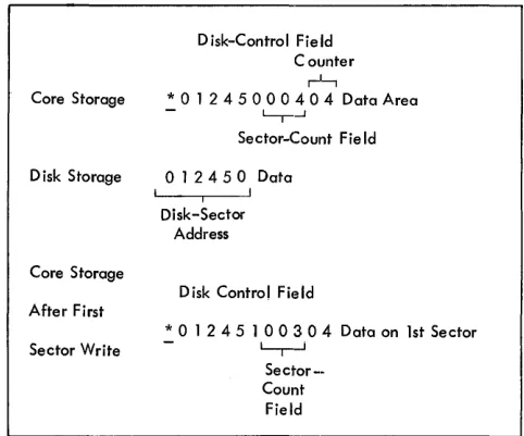
As the first sector is read from disk storage, the first three digits of the record being read are placed in the sector-count field of the disk-control field in core storage. Therefore, if a variable number of sectors are to be read from disk storage, the sector-count field must contain a value greater than 001 to cause the first sector to be read. The first three positions of the first sector read contain the number of additional sectors to be read. Figure G-22 illus-trates the operation of an overlay instruction, which causes four sectors of data to be read from disk storage into core storage.
The operation proceeds as a normal read opera-tion with appropriate changes to the. core-sector address and· sector-count fields.
[image:20.613.311.553.196.289.2]Word Marks. Because the exact number of positions of data to be read from disk storage may not be known when this operation is initiated, place the group-mark with a word-group-mark (signaling the end-of-opera-tion) one position to the right of the last possible character to be read using this instruction. If the maximum number of records is not read, the read into storage stops because the end of sector is reached and the sector-count field is all zeros before the group-mark with a word-mark is sensed. The wrong .. length-record indicator also turns ON. The programmer can check core storage in this case to see if the correct number of sectors have been read. This can be accomplished by setting up a counter in the fourth and, if necessary, fifth position of the first sector of the record. This counter, when the read operation is completed, is located in the first and/ or second position of the data record in core storage. These positions can be used to check the number of sectors in the record. These counter posi-tions should equal the actual number of sectors in the record. For any record length other than single-sector records, reading data from disk should have stopped at B
+
6+
NsLs. If it did not, then an error did occur and appropriate action should be taken.If a correct read has occurred, the error indication can be disregarded.
Special consideration must be given to single-sec-tor records when read in the secsingle-sec-tor-count overlay mode. When the read operation begins, the first three characters of the record overlay the sector count. In this case, 0'0'0' is read in and overlaid. How-ever, the machine does not detect a zero sector count except when produced by automatically de-creasing the sector-count field. After reading the
Core Storage
D isk-St'orage
Core Storage
After First
Sector Read
Disk-Control Fie Id
* 0 1 2 4 5 0 n n n Data Area
- L~
Any Number ( Greater than 1)
01245000304 L I I~---l Disk Sector
New-Address Sector Count
D i sk-Contro I
Field Counter
. - ---,,t-,
.! 0 1 2 4 5 1 0 0 3 0 4 Data from 1st Sector
Figure G-22. Read Disks - Sector-Count Overlay Operation
single-sector record, the address is increased by one and an equal compare is sought on the next sector. When found, the sector count field is decreased by one again, resulting in a count of 999. Because the sector count field is not all zeros when this occurs, the wrong-length-record indicator is turned ON. When an initial sector count of 003 is used and the first three digits of the first sector read are GOO (the three digits to be overlaid), the following occurs:
1. The 0'peration will not stop because the seotor count has not been decreased to aGO'.
2. The sector address has been increased and the second sect0'r is read.
3. The special-add operation (used to keep track 0'f the sect0'r count) decreases the seotor count (0'0'0) to 999.
Because the last step (item 3) does not produce a carry to increase the sector address, an address compare occurs 0'n the attempt to read the third sect0'r. The address compare does not occur when the initial sector count is 001, but the read will con-tinue until a group-mark with a word-mark is sensed in core storage.
Single-sector and multiple-sector read operations cannot be interspersed (using the M/L %F5 BBB R instruction) without prior knowledge of exactly
when each read will occur.
When a file includes single-sector records, a spe-cial routine must be included to verify the validity of the record read. Before executing a read, a spe-cial character that would never be found in the last position of a record can be moved to the lGGth position of the input area. The wrong-length-record routine can then check to see whether the counter in the first position of the record contains a one ( 1 ). If so, it would check to see that the special character has been overlaid. If it has, the record was read in its entirety.
Timing. T
=
N (LI+
1) ms+
2N s+
disk rotation. 0'(; 44 ms is maximum time for disk rotation. 24 ms is average time for disk rotation.
4 ms is minimum time for disk rotation.
Note: Before reading starts, an automatic comparison is made of
the record address in core storage with the record address on the disk. This check is made as each sector is read. If the addresses are not the same, the unequal-address compare in-dicator is turned ON, and the data on the disk cannot be read into storage.
Address Registers After Operation.
I-Add. Reg. A-Add. Reg.
NSI B+6
B-Add. Reg. B + 8 + NsLs
Example. Read into core storage a variable number of sectors that contain the data for a record beginning at location 0900 (labeled INPUTB). The disk-con-trol field is located in the ten positions preceding the label (0890-0899), Figure G-23.
SPS
Autocoder
~,
lSI ~peroti~ 21 5 0 RDCU I NPUT& -I,o~
OPERAND
4~ , ~
Lobel
Assembled Instruction: M. %F5 890 R
Figure G-23. Read Disk with Sector Count Overlay
Write Disk Sector(s)
Instruction Format.
Mnemonic Op Code A-address B-address d-character
SPS MU M %Fl xxx W
A \VD
Function. This instruction causes record data in core storage to be written on a disk record. The digit 1 in the A-address (%Fl) specifies that a sector opera-tion is to be performed. The number of sectors to be written is specified by the sector-count field. The writing of the disk record is stopped by a group-mark with a word-group-mark in core storage and by the end of sector.
Writing begins at the address contained in the core-sector address field and continues for the num-ber of sectors specified by the sector-count field.
The core-sector address field is increased by one for every sector written. The sector-count field is
reduced by one as a sector is written.
When the sector-count field reaches 000, an end-of-operation is indicated to the system. An error con-dition results from any disk sector read or write operation that begins the operation with a sector count of 000. Before the first sector is transferred, a one (1) is subtracted from the sector-count field, resulting in a sector count of 999. Data would then be transferred until a group-mark with a word-mark is encountered in core storage. Because the sector count is not zero at this time, the wrong-length record and any-disk condition indicators are turned ON.
The B-address specifies the high-order position in core storage of the disk-control field, and is followed by the data to be written on the disk.
The W in the d-character position signifies a write operation.
Refer to Figure G-19 for a functional schematic of a write operation.
Word Marks. A group-mark with a word-mark must be
one position to the right of the last character of the record in core storage. The writing of data stops when the end-of-record is reached on the disk and a group-mark with a word-mark is sensed in core stor-age. If the group-mark with a word-mark is sensed before the end of a record, the remainder of the disk record is filled with valid blanks (C-bit), and the any-disk condition and wrong-length-record in-dicators are turned ON.
Timing. T
=
N (Lr+
1) ms+
2N s+
disk rotation. (I,1't44 ms is maximum time for disk rotation. 24 ms is average time for disk rotation.
4 ms is minimum time for disk rotation.
Notes: Before writing starts, an automatic comparison is made
of the core-sector address with the record address on the disk. This check is made for each sector written. If the ad-dresses are not the same, the unequal-address-compare indi-cator is turned ON, and the data in storage cannot be written
on the disk.
If the data in core storage contains characters with word marks, only the CBA8421 portion of the character is written on the disk (the word mark is ignored).
A WRITE DISK CHECK instruction must be performed
follow-ing a write-disk operation unless an error occurred durfollow-ing the write operation. No other disk-storage operation can be performed until the check of data written on the disk is accomplished.
Address Registers After Operation.
I-Add. Reg. A-Add. Reg. B-Add. Reg.
NSI B+6 B + 11
+
NxLsExample. Write a disk record (one sector) from the data in the area labeled INPUT A (first position of data is at 0600). The disk-control field is located in the ten positions preceding the label (0590-0599), Figure G-24.
SPS
Autocoder
Lobel
Assembled Instruction: M. %Fl 590 W
Figure G-24. Write Disk Sector
Write Disk Sector(s) with Word Marks
Instruction Format.
Mnemonic
SPS LU
A WDW
Op Code
1:
A-address
%Fl
B-address
xxx
d-character
W
Function" This instruction is similar to the WRITE DISK SECTOR instruction, except that word marks set with the data in core storage are recorded on the disk record. This mode of operation permits writing pro-grams on disk records for system use. Ninety posi-tions of data with word marks are recorded on each sector during the write operation.
Word klarks. A group-mark with a word-mark one position to the right of the last character of the rec-ord in core storage terminates the write operation.
If the group-mark with a word-mark is not sensed at the same time as the end of a record, the re-mainder of the disk record is filled with valid blanks
( C-bit), and the any-disk condition and the wrong-length-record indicators are turned ON.
Timing. T
=
N (1.1+
1) ms+
2Ns+
disk rotation. ~444 ms lis maximum time for disk rotation. 24 ms is average time for disk rotation.
4 ms is minimum time for disk rotation.
Notes: The programmer should be certain that all records on a
specific track are written in the same mode (M or .1 opera-tion code). Otherwise, track operaopera-tions are not possible.
Before writing starts, an automatic comparison is made of the record address in storage with the record address on the disk. If the addresses are not the same, the unequal-address-compare indicator is turned ON, and the data in stqrage can-not be written on the disk. A write-disk-check operation must be performed following this instruction.
Address .Registers After Operation.
I-Add. Reg. A-Add. Reg. B-Add. Reg.
NSI B+O B + 11
+
NsLs [image:23.613.328.569.502.703.2]Example. Write a disk record, with word marks, from the data in the area labeled OUTPUT (first position of data is 0600). The disk-control Held is located in the ten positions preceding the label (0590-0599), Figure G-25.
Autocoder
Assembled Instruction: ~ %Fl 590 W
Figure G-25. Write Disk Sector with Word Marks
Write Disk with Sector-Count Overlay
Instruction Format.
Mnemonic Op Code A-address B-address d-character
SPS MU M or L %F5 xxx W
L U (word m"';rks)
A WDCO
WDCOW (word marks)
Function. This operation is similar to the WRITE DISK SECTOR instruction except that the sector-count Held of the disk-control field is automatically decreased by one and then written in the first three data posi-tions of the first sector written. The digit 5 in the A-address specifies that an overlay operation is to be performed.
Therefore, if a variable number of sectors are to be written on disk storage, the sector-count field in core storage should contain the number of sectors to be written. The first three data positions of the first sector written contain the number of additional sectors that were written. Figure G-26 illustrates the operation of an overlay instruction, which causes four sectors of data to be written from core storage onto disk storage.
The operation proceeds as a normal write opera-tion with appropriate changes to the core-sector ad-dress and sector-count fields.
Word Marks. A group-mark with a word-mark should be placed one position to the right of the last sector to be written. The group-mark with a word-mark must be placed at B
+
7+
NsLs to avoid a false wrong-len