-
-=:::::::::.
- -
- -
-
.
--
- -
--
-
--
-
-
-:::::
~:'~~:;~
----
-
::::
- : :
- , , -
,Application Program
1401 Data Analysis and Reduction System
(1l401-CA-04Xt Version 2
Programmer's and Operator's Manual
The IBM 1401 Data Analysis and Reduction System is a
powerful series 6f programs to generate tabular and statistical reports from existing card or magnetic tape files. Three types of programs, modified by control cards to suit individual requirements, operate under the control of a monitor program.
The data preparation programs accept punched cards or
magnetic tape in a variety of formats, and add, delete, and/or' change the format and content of each record or user-selected records from the data file. Records may be selectively extracted for information retrieval purposes.
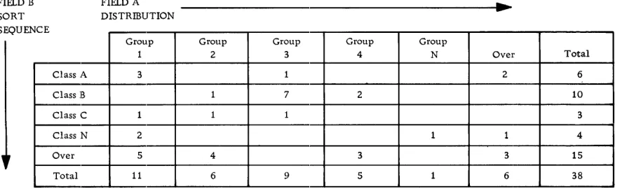
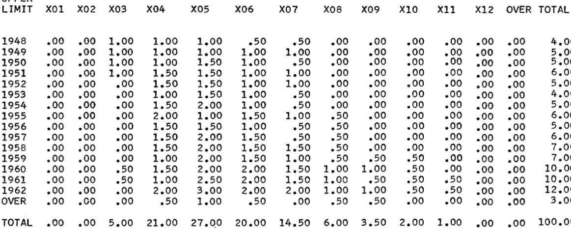
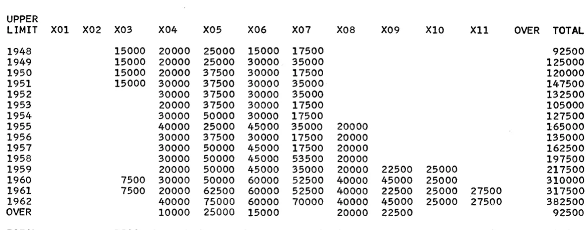
The report programs produce, as specified in control cards, m.atrix-type, frequency tabulation, listed, punched and statistical reports. The matrix reports, consisting of horizontal columns and vertical rows, present crossfooted di.stributions expressed in percentages, counts, or sum.maries as required. The frequency tabulation report contains the frequency of occurrence of the values in a specified field of every data record. The quantitative statistical report contains parameters such as the mean, variance, and standard
deviation, along with a matrix-type presentation of frequency, count, and percentage for each defined group.
The utility programs provide the ability to list records, control program operating sequence, prepare and modify the system tape, and perform various other functions to facilitate using the system.
The programs can be used in almost any industry to provide a concise analysis of subjects such as inventory activity, traffic characteristics, sales analysis, communications systems, engineering studies, medical reports, payroll analysis, and personnel studies.
CONTENTS
Introduction . . . . • . . . •
Program Classifications . System Description . • . Operating Programs . Storage Assignments. • Control Cards . . • . .
General Description of Error Handling . System Configuration Requirements.
Chapter 1: Input Programs • . . .
Data Input Control Program . . Output Data Tape Format. Control Card Formats • • .
Example of Field Definition Card Use • • Messages • . . . • • • • . . • •
Variable Input Control Program •• Purpose' • • • • • . •
Input Specifications . Output Format . . . . Output Specifications • Messages . • • • . • • Control Cards. • • .
Preparing Control Cards ••• Use of Field Dividers. . •
Field Divider Specifications . . . • . Field Divider Codes . . . . • . • Example
Messages • 0 0 • • 0 •
Chapter 2: Data Manipulation Pro~rams . .
Field Edit Program • • • . Field Adjustment . • • Control Card Format. . Messages . . • . . . . Considerations • 0 • • •
Symbol Substitution Program Control Card Formats Sequence Control .
Messal~es • . 0 • • • • •
Other Messages. 0 • • • •
Field Redefinition Program Redefining Fields • . . Control Card Formats Redefined Data Record •
Messages • • . . . • Program Operation. . Data Extract Program. • Function . . . . • • . • Control Card Format . Compare Functions 0
Messages 0 • • 0 0
Program Operation 44 46 4:7 4:7 47 49 150 52
Chapter 3: Report Programs • • . 0 0 • 0 0 • 0 • • • • • • • 0 0 • • • • • • • • • • ,53
Matrix Report Program • • . . • • 0 0
Function. 0 0 • • • 0 • 0 0 0 • 0 • 0 0 • 0 •
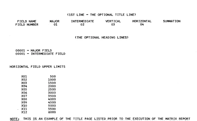
Using the Matrix Report Program Title Page Format 0 0 0 • •
Control Card Formats Messages 0 0 0 0 • • • 0
Quantitative Statistical Parameters Report Program. 0
Function 0 • • • 0 • • • •
Control Card Formats Program Operation 0 0 0
Messages 0 • • • 0 0 • •
Data Record List Program Record List 0 0 • 0
List X Program. 0
Edit and List Tabulate. Punch and List
Use of Control Cards for Titles and Headings 0
Messages 0 • • 0 • • • 0 0 0 • 0 • • •
Program Operation 0 • • 0 • •
Data Record Tabulate Program 0
Function. 0 0 • • 0 • •
Control Card Format 0 •
Messages, Phase 1 0
Messages, Phase 2 Considerations
Chapter 4: System Programs Monitor • • . . . 0 0 0 0
Control Messages 0 • • 0
Input/Output Program 0
Control Messages. . • Blank Identification Program
Control Card Format Messages 0 • • •
Utility Programs 0 0
Sense Switch Utilization • System Operation Notes • •
Tape Handling. • Restart.
Program Halts •
Chapter 5: System Generation and Modification Programs
Tape Load Program • . • System Tape Creation Control Messages. . . System Modify Program. Function • . • . • • • . Control Card Formats Messages • • • • • . • •
System Rules for Operational Programs
101 103 103 104 104
108
108 108 110 111 111 112 113 116
INTRODUCTION
The IBM 1401 Data Analysis and Reduction System is a powerful series of programs to generate tabular and statistical reports from existing card or magnetic tape files. Three types of programs, modified by control cards to suit individual requirements, operate under the control of a monitor program.
1. The data preparation programs accept punched cards or magnetic tape in a variety of formats, and add, delete, and/or change the format and content of each record or user-selected records from the data file. Records may be selectively extracted for infor:mation retrieval purposes.
2. The report programs produce, as specified in control cards, matrix-type, frequency tabulation, listed, punched, and statistical reports. The matrix reports, consisting of horizontal columns and vertical rows, present crossfooted distributions expressed in percentages, counts, or summaries as required. The frequency tabulation report contains the frequency of occurrence of the values in a specified field of every data record. The quantitative statistical report contains parameters such as the mean, variance, and standard deviation, along with a matrix-type presentation of fre-quency, count, and percentage for each defined group.
3. The utility programs provide the ability to list records, control prograrn operating sequence, prepare and modify the system tape, and perform various other functions to facilitate using the system.
These programs can be used in almost any industry to provide a concise analysis of sub-jects such as:
• Inventory activity • Traffic characteristics • Sales analysis
• Communications systems • Engineering studies • Medical reports • Payroll analysis • Personnel studies
The system, with its ability to accept records from cards or magnetic tape in a variety of formats, ean provide management with new insight into complex activities without extensive programming and data reduction effort.
-1·-PROORAM CLASSIFICATIONS
The programs in the system may be divided into six general groups:
1. Input Programs
2. Data Manipulation Programs 3. Data Extract Program 4. Report Programs 5. System Programs
6. System Generation and Modification Programs
A brief description of the functions of each of these programs follows:
Input Programs
Data Input Control - accepts fixed- or variable-length, fixed-format card or tape records and converts them to a format suitable for the data preparation or report programs. Input fields are defined by their position in the record. Subsequent references to fields are by field number, from 01 to 25. Serial numbers may be assigned to each record if desired.
Variable Input Control - accepts variable-length, variable-format tape or card records and converts them to a format suitable for the data preparation or report programs. Input fields are defined by field divider codes, consisting of length, occurrence, and character representations.
Data Manipulation Programs
Field Edit - provides right or left adjusting of fields in formatted tape to prepare for sorting or report producing.
Field Redefinition - combines, separates, adds, or deletes fields in formatted tape records.
Data Extract Program
Extract - selects records and creates a new file based on relational conditions, testing all records or only those records occurring at user-specified intervals. This program is a valuable aid in statistical sampling and information retrieval.
Report Programs
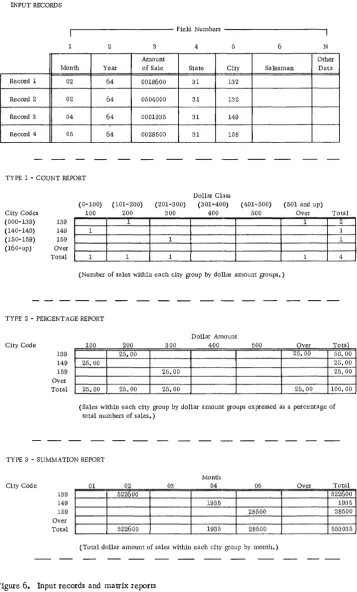
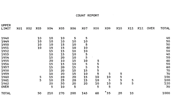
Matrix Report - produces reports expressing counts, percentages, or summation of values.
Data Record List - prints a formatted listing of input records by fields. Fields may have decimal or comma punctuation, sign control, and suppression of nonsignificant zeros.
Data Record Tabulate .- produces a report on the frequency of occurrence of the values in a specified field of every data record. Each value that occurs within the field is listed, along with the frequency of occurrence, that is, the number of times the sam.e value appe!ars in successive records.
Quantitative statistical Parameters Report - computes and prints a comprehensive tabu-lar report of statistical parameters such as mean, variance, and standard deviation.
~em Programs
Monitor - controls system programs.
I/O Program~ - consists of common input/output routines for all system programs using magnetic tape.
Blank Identification - provides for immediate reuse of any operational program, or produces a formatted print of the system program tape, or prints the program identifica-tion table from the system via the monitor.
System Generation and Modification Programs
Tape Load - prepares a program system tape from cards.
General Utility - provides a storage printout with optional printouts of the input, output, and system tapes.
Modify System - duplicates and/or modifies the system tape by adding, deleting, or replacing system programs.
SYSTEM DESCRIPTION
Input data may consist of:
1. Cards _. with one or more cards used to create one record.
2. Blocked or unblocked fixed-length tape records. The maximum single record size is 999 characters; maximum block size is 1500 characters.
3. Unblocked variable-length tape records. The maximum usable portion i.s the first 999 characters. These records may not contain record marks, tapemarks, or groupmarks as data characters.
4. Variable-length records with variable-length fields, such as messages, reports, or data, to be converted from punched paper tape to cards or magnetic tape, and sub-sequently reformatted to fixed-length, fixed-field records for processing.
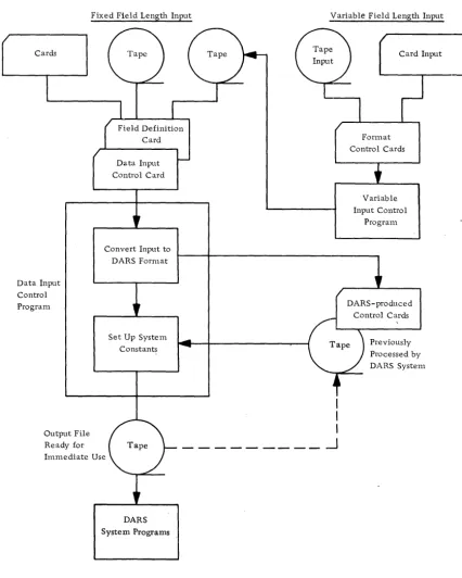
Figure 1 illustrates how the various types of input are accepted by the system.
-3-Cards
Data Input Control Program
Fixed Field Length Input
Data Input Control Card
Convert Input to OARS Format
Set Up System Constants
Output File Ready for Immediate Use
OARS System Programs
Figure 1. Input flow in the system
Variable Field Length Input
I
I
I
.-J
Ca,d Input ]
Format Control Cards
Variable Input Control
[image:10.623.97.523.64.596.2]Proeessing
A monitor controls the system, permitting the running of operational programs with minimum operator intervention. The same input data may be used to produce a variety of reports. The output of one program can be used as the input to another, to provide a multilevel analysis. Original input data may be saved on request.
Operator intervention is minimized by internally scheduling the output tape unit of the current program to become the input tape unit for the next program. Programs may be run in any logical order by arranging the control cards accordingly.
Control cards are checked for format and reasonableness. The detection of an error that may cause a program malfunction or loss of data will set a system error switch on. Subsequent control cards in the card reader are checked, and error messages printed, but the programs are not executed. This feature prevents dependent programs from attelnpting to process improper data.
Reports are produced on the 1403 Printer; punched cards are produced on the 1402 Card Read Punch.
Program Modification~
User-written modifications (additions, deletions, or changes) may be made to the system as required. A systenl program is included to facilitate locating errors in new additions to the operational program file.
The system can duplicate itself on a second reel of magnetic tape.
,Tape Labels
A control card indicates the presence or absence of an 80-character header label on a single reel of input, or on the first reel of a multi reel file. All subsequent reels in a multireel file must contain header labels.
OPERATING PROGRAMS
The operating progranls are stored on magnetic tape and loaded as required by a system monitor program. Control cards are analyzed by the system monitor, which selects and loads the appropriate program. At the end of the program run, control is returned to the system monitor.
Operating programs on the system tape are written in load mode, one program or pro-grarn segment per block. Programs requiring more than 4000 storage positions are written as two or more blocks.
-5-STORAGE ASSIGNMENTS
For this system, 1401 core storage is logically divided into three areas:
• Area 1. Positions 001 - 599. The monitor occupies positions 340 to 599. Positions 001 through 332 are reserved for the card reader, punch, printer, and index
registers.
• Area 2. Positions 600 - 4599. This area is reserved for the current operational program. Only one program from the system tape may occupy this area at anyone time.
• Area 3. Positions 4600 - 7999. This area is reserved for system constants, tables, a 1500-position common tape input/output area, the common tape input/output rou-tine, an SO-character header and trailer label area, and the calling sequence for the general utility program.
CONTROL CARDS
The data input control card defines the input card or magnetic tape file. The field defini-tion control card defines the fields within the input file. Fields not used need not be defined.
Operational control cards describe the operations to be performed on the defined input file and the defined fields within each record.
Information from the data input control cards is placed in tables in storage at the begin-ning of each run. When the monitor reads in the operational control cards, the appropri-ate programs are loaded and executed. Upon completion of an operational program, control is returned to the monitor, which reads in the next control card and loads in the appropriate operational program.
GENERAL DESCRIPTION OF ERROR HANDLING
SYSTEM CONFIGURATION REQUIREMENTS
The Data Analysis and Reduction System operates on the IBM 1401 Data Processing System with the following minimum configuration:
1401 Processing Unit, 8K
Three '729 or 73~0 Magnetic Tape Units (four required if Error File option is used with the Variable Input Control Program)
1402 Card Read Punch
1403 Printer, Model 2
Advanced Programming Feature
High- Low- Equal Compare Feature
Multiply-Divide :Feature
Sense Switches (required for Variable Input Control Program)
-7·-CHAPTER 1: INPUT PROGRAMS
DATA INPUT CONTROL PROGRAM
The program creates a formatted data tape from the user-furnished input data file and sets up common systems constants and tables.
Input data may be on cards, blocked or unblocked fixed-length records on magnetic tape, or unblocked variable-length records with fixed-length fields on tape.
Maximum record length is 999 characters. Maximum blocking factor is 99. Maxirnum block length is 1500 characters.
Single-reel tape input may contain a header label, with or without a following tapenlark. Multireel or multifile multireel input must have header labels on all but the first reel, where the header label is optional.
Two or more separate files with the same format may be combined as described under "Operating Procedures", using sense switch B.
Field selection is provided. The number of card or tape records to be combined into one output record may be specified. The user indicates the fields to be used in the output record and their arrangement.
In order to facilitate sorting on the IBM 7080 or IBM 7090, data records may be-padded to a multiple of five or six character positions.
The program accepts input from a previous system run without modifying the data re-cords. The data input control card must precede any rWl of one or more system pro-grams to set up the common system constants and tables describing the file and records.
With card or tape input, the user may have a serial number automatically inserted in every output data record. The field number, starting serial number, and increment per record must be provided in the control card.
Two additional options are available when using card input:
1. When more than one input card is used to create a single output record, a user·-specified control field may be checked on each card within each card group. If an Wlequal condition is found within the card group used to construct an output" record, the first· card of the group is dropped from the file and listed on the printer. The next card is read in and the check repeated.
Output Data Tape Format
Data tapes produced by the data input control program have a system header label re-cord, 80 positions in length, not followed by a tapemark. Individual or blocked records follow the header label record. The trailer label, 80 positions in length, is preceded by and followed by a tapemark. Maximum block si,ze is 1500 characters. Each output record has a record mark as the last character.
The header label is automatically generated by the program from information contained in the control cards. With normal DARS processing the user need not concern himself with the format of the 'header and trailer labels. It is offered here as additional infor-mational material. The header label format is:
Position
1-4
5-12
13
14-Ui
16-1'"
18-20
21-22
23-24
25-70
71-80
Content
1 HDR Blank
Number of padding characters per record including record mark. The minimum entry is 1, the maximum 6.
Number of f:ields per record
Blocking factor (number of records per block)
Record length, including padding and record mark
Length of first field in record Length of second field in record Lengths of successive fields in record, frOIn third to twenty-fifth field. Two positions per field, as in columns 21-22, and 23-24.
Not used The trailer label format used is as follows:
Position
1-4
5 6-80
Content
1 EOR if end of reel 1 EOF if end of file Blank
Not used
-9-The maximum file specifications are as follows:
Block length: Field length: Record length: Blocking factor:
Control Card Formats
Data Input Control Card
1500 positions 99 positions 999 positions
99 records per block
This card defines the input file, and permits optional serial numbering of records, sequence checking, and output blocking.
Column
1
2
3
4-6
7-8
9-10
11
Contents
*
(control card identification) Input format indicator:1 - Input file in acceptable format because it was produced by a previous run of this program.
Blank - Input is not in DARS format, not processed by the system before this time, or requires
adjustments in record formats.
Type of input - use when column 2 is blank: Blank - card input
1 - unblocked tape records 2 - blocked tape records
Length of input record in characters. Maximum record length is 999 (see note).
Number of input records per block. Maximum blocking factor is 99 (see note).
Number of input records, as defined by field definition control cards, that constitut~ one output record.
Maximum of 99. If the value is greater than 1, it must be evenly divisible into the value in columns 7 and 8 of this control card (see note).
Column
12-14
15-19
20-22
23
24-25
26-34 35-37 80
Contents
Length of output record in characters. The number of characters to be extracted from the input record or records to constitute one output record, plus the number of characters for serialization if the option is used. Maximum of 999 (see note).
Def~nition of control field in cards when using multiple card input for each output record (see note):
Blank - no check made by system
Columns 15-16 _. length of identification field (see note) Columns 17-19 - low-order (rightmost) card column of
identification field (see note)
If these control card columns (15-19) are punched, the defined field is compared to the same field in each card of the group of cards used to constitute a single output record. The field must be equal within the group. Sequence check position of input record (see note).
This single card column or tape record character position is used to sequence check input records within a group of card or tape records used to constitute a single output record. An equal or ascending sequence is acceptable within each group. If columns 20-22 of this control card are blank, no check is made.
Generate serialization number:
1 - insert a serial number in each output record Blank - no serialization desired
Output field number to contain serial number. Field numbers are assigned on the field definition card(s) (see note).
Starting serial number to be placed in the first output record Increment of serial number from record to record
Record padding indieator. To facilitate .sorting, each record may be padded with 9s so that the number of characters per record is a multiple of 5 or 6.
5 - Pad records to a multiple of 5 for sorting or processing on the IBM 7080
6 - Pad records to a multiple of 6 for sorting or processing on the IBM 7090
Any value other than 5 or 6 indicates no record padding. Note: These fields must contain only the numerical characters from 0-9 with
leading zeros.
First Field Definition Card
Up to 25 fields can be defined by using the first and second field definition cards. Only the first card is required when twelve or fewer fields are defined. The output fields are located as defined.
Column
1 2 3-4
5-10
11-16
17-22 23-28 29-34 35-40 41-46 47-52 53-58 59-64 65-70 71-76 77-79 80
Contents
A (control card identification)
1 (indicates first field definition control card)
Number of fields to be defined (see note). Maximum of 25 fields.
First output field, to consist of input field as follows: 5-7 - Input high-order character position in record 8-10 - Input low-order character position in record Second output field, to consist of input field as follows:
11-13 - Input high-order character position in record 14-16 - Input low-order character position in record Third through twelfth output fields follow the same format: as the first and second fields (see note):
Field 03 Field 04 Field 05 Field 06 Field 07 Field 08 Field 09 Field 10 Field 11 Field 12 Unused
Total number of field definition cards (1 or 2) used
Second Field Definition Card
This card is a continuation of the first field definition card and is used only if more than twelve fields are defined.
Colunln
1
2
3-8
9-14
15-20
21-26
27-32
33-38
39-44
45-50
51-56
57-62
63-68
69-74
75-80
Contents
A (control card identification)
2 (indicates second field definition card)
Thirteenth output field, to consist of input field located as follows:
3-5 - Input high-order character position in record
6-8 - Input low-order character position in record Fourteenth through twenty-fifth fields defined as in control card columns 3-8 (see note)
Field 15
Field 16
Field 17
Field 18
Field 19
Field 20
Field 21
Field 22 Field 23
Field 24
Field 25
Note: These fields must contain only the numerical characters from 0-9 with leading zeros. Unused fields are left blank.
Control Card Use
TheBe card(s) are read in the sequence presented, with the data input control card followed by the first (and second) field definition card(s) ..
When the input is a card file, the data cards must follow the data input and field definition control cards. A blank card with a llozenge (I:!) in column 80 follows the last data card.
-13,-A set of these control card(s), defining the output file, are punched by the D-13,-ARS system at this time for use in subsequent runs if the input to this program is a card file or a tape not in the required system format.
Linked program runs, where system programs are executed immediately after the data input control program, do not require the DARS-punched control cards. The necessary control information is retained in storage for use by the subsequent linked programs in the run.
Blank Field Generation
Blanks may be inserted in the output data records by the user., These blanks may he used to expand a data record, or to enable data fields to be formatted for listing
purposes. To insert blanks, the user must define the length of the output record larger than the length of the input record specified on the data input control card. The
specified length of the output record should therefore reflect the required number of blanks to be inserted. For example, to insert a field of ten blanks between the first and second of three prescribed fields, and a field of ten blanks between the second and third of these fields, the length of the output record is increased by twenty characters. The enlarged record is padded with twenty blanks in the low-order position by DARS. The field definition control cards must reflect these two additional fields between the designated fields. To avoid inadvertent insertion of the record mark or groupmark, which may be part of the input data record, the low-order position of the. input data record should not in this case be defined as part of the output record.
The data input control program will manipulate the fields and insert the blank fiel<js in the proper positions.
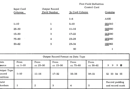
Example of Field Definition Card Use
Assuming an input card file, select certain fields in a specified sequence to form an output data tape record. The source card columns, the output tape forl1;lat, and the field numbers are shown in Figure 2. The record padding shown was specified in
column 80 of the associated data input control card. Note that in the example the contents of columns 25-30 are included in both fields 2 and 3 of the output.
Messages
All messages are followed by a computer halt, except as noted.
CONTROL CD SEQ ERR
This is an error in the card numbering of the field definition control card(s) in colum.n 2 and/or column 80 (card *1 only). The card in error is listed on the same line as this message.
DATA RCD EXCEED MAX
First Field Definition Input Card Output Record Control Card
Columns Field Number In Card Column ~
-1-4 A 105
1-:10 5-10 .QQ!010
25,·30 2 11-16 ~030
15,·30 3 17-22 .Q!.§030
75,·80 4 23-28 ~080
50,·62 5 29-34 Q§Q062
80
Output Record Format on Data Tape Data. From From From From From
Source cc 1-10 cc 25-30 cc 15-30 cc 75-80 cc 50-62 9 9 9 =t= Output Tape
Record 1-10 11-16 17-32 33-38 39-51 52 53 54 55 Positions
Field Record padding
Numbers 1 2 3 4 5 and record mark
Figure 2. Data :input and output example. data input control program
[image:21.612.101.518.63.348.2]-15-FIELD DEF CONTROL CARD MISSING
A field definition control card has not been recognized by the program.
FIELD DEF CONTROL CARD 1 ERROR CLMS 3-4
Columns 3 -4 of the field definition control card contain a nunlber not within the limits of 01-25, inclusive.
INPUT CONTROL CARD ERROR IN COLUMN 7-8 or 9-10
Columns 7-8 or 9-10 indicate a blocking system that the program is not able to handle.
INPUT RCD OUT OF SEQUENCE REC BYPASSED
When checking the sequence, a data record was found to be out of sequence. The card is listed on the printer and bypassed, and the run continues. The processor is not halted.
OUTPUT RCD EXCEEDS MAX
The output record size exceeds 1500 character positions.
*RCDS NOT PADDED
The padding indicator, card column 80 of the data input control card, is not 5 or 6. No padding will be added to records. Processing continues.
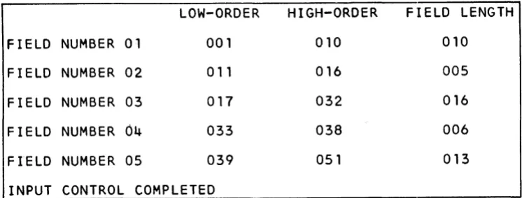
In addition to the above, messages are printed indicating the start and end of each program. The field definition table with title and headings, giving the format of the output tape record, is also printed (see Figure 3).
LOW-ORDER
HIGH-ORDER
FIELD LENGTH
FIELD NUMBER
01 001 010 010FIELD NUMBER
02 011 016 005FIELD NUMBER
03 017 032 016FIELD NUMBER
04
033 038 006FIELD NUMBER
05 039 051 013INPUT CONTROL COMPLETED
[image:22.613.96.469.469.610.2]VARIABLE INPUT CONTROL PROGRAM
This progranl provides a method for converting machine-readable information in an
irrel~ular format to. fixed-length records suitable for further analysis by the system. Although particularly suited to analyzing communications traffic such as data or admin-istrative messages, the program can be used for a wide variety of applications with similar characteristics. The resultant output consists of fixed-length records in a format specified on control cards.
Input Specifications
Data records may be up to 999 characters in length on magnetic tape or punched cards. Card records must have a groupmark following the last character, or the 999th character. Tape records must be unblocked. Groupmarks within a card or tape record will
termlinate the record.
Multireel magnetic tape files must have a header record on each reel, except the first reel where it is optional. Single reel files mayor may not have a header record.
Information on punched paper tape can be converted to punched c3;I'ds by using the IDM 46 Tape to Card Punch or 47 Tape to Card Printing Punch. Information on punched paper tape can be converted to magnetic tape by using the IBM 7765 Paper Tape to Magnetic Tape Converter.
With the IBM 46 or 47, the control panel should be used to:
1. Either bypass line control characters or, if they are to be used as field separators, convert them to any desired character.
2. Convert a unique character, or combinations of characters found at the end of each input record to a group mark to indicate the end of the record. The" Figures H" character at the end of telegraph-type messages is an example.
3. 'When the group mark character is punched, the card should be skipped out so that ,each new record starts in the first column of a card.
With the IBM 7765, the end-of-record indication should initiate a write operation so that an interrecord gap exists between each input record. otherwise the instructions for the IBM 46 apply.
A reeord mark in a data card input file will cause error conditions. A simple editing program can be written to read the data cards and eliminate or change those containing record marks.
The group mark at the end of any data record (rnagnetic tape records included) must be defined as the divider (last character) of the last input field in the record. Control code A can be used for this ]purpose.
Output Format
The output file consists of fixed-length blocked or unblocked records. A field three characters in length may optionally contain a count of the number of characters in the entire input record, including the groupmark.
Output Specifications
Program output consists .. of a file containing reformatted copies of input records that met the specifications, and an optional output file containing copies of input records that: did not meet the specifications. The optional file can be printed, reviewed, and reentered into the system with a new format control card.
Acceptable output records f written on tape unit 3, may be blocked at the user's opti.on. Each block may contain up to 1500 characters, including the record mark following each record. 1'he last block will be padded with 9s as required.
The optional error tape on tape unit 5 will contain unblocked records in the original input format. Card records exceeding 999 characters plus a group mark are cOllsidered as error records. The optional tape will contain the first 920 characters and the last card containhlg the groupmark. Tape records exceeding 999 characters are not considered as errors but are truncated to the maximum acceptable length of 999 characters.
Messages
Informational status and error conditions are indicated in code on the printer. The printing of unacceptable data records and the associated code message is optional. The normal full printout of error records can be limited to the first hundred characters by turning sense switch E on. Sense switch D stops all error records from printing.
Control Cards
First Format Control Card
Column
1
2
3
4
Contents
Y (control card identification)
Blank indicates one control card, any other punch indicates two cards
1 - Card input 2 - Tape input
Blank - unblocked tape record output.
Other than blank - tape output to be blocked within 1500-position limitation.
5
6-7
8-9 10-11
12
13
14
15-80
Contents
Last card code for card input: Blank - sense switch A used.
Other than blank - a card with LAST CARD punched in columns 1-9 will be used to terminate the input.
If neither is present subsequent cards will be treated as a continuation of the data.
Number of data input fields Number of data output fields
Input record or message length option:
00 - Exclude input record character, count from the output record
Other than 00 - The number of the output field to
contain the character count of the input record
Error tape option. If a copy of all input records that do not meet the specifications is desired, punch any digit in this 'column. Blank indicates that the error tape will not be produced.
Input file header label record on single-reel file or first reel of a multireel file:
Blank - no header record
Not blank - header record present
Record padding indicator. If each output record, whether the file is blocked or unblocked, is to be a multiple of a certain number (including record mark), the appropriate number (2-9) is entered.
Blank - no record padding 2-9 - record padding multiple
o -
pad to multiple of 10The remainder of the format card is used for field dividers, the codes enabling the program to manipulate the data fields
Second Format Control Card
This card is prepared in the same manner as columns 15-80 of the first format card.
-19-Preparing Control Cards
Fields dividers are discussed in detail in subsequent sections e
A record mark must follow each field divider statement. Two record marks indicat.e the end of the last control card containing field dividers.
Use of Field Dividers
The program logic consists of a left-to-right scan of the input file records, searching for characteristics that would identify the end of a field, either by the known characteristics of the beginning of the following field, or by character used to actually separate fields.
The test characteristics used are:
• One or more known characters appearing an exact number of times in succession, such as FFF, or BARBARBAR.
• One or more known characters appearing at least a minimum number of times in sequence.
• Certain characters appearing, with one of them repeated a specific number of tinles, or at least a minimum number of times, such as the letter A in BAAR, BAAAAAR, or BAR.
• A field defined by the change from alphabetic to numeric characters indicating the beginning of the next field, thereby serving to identify the preceding field.
• Combinations of these tests as alternate means of identification.
In order to use these means of identification, the input records must have some degree of consistency, in that each field within a record must occur in the same order as fields in all other records, although the field lengths may be irregular ,and fields may be missing or replaced by other fields in some records.
A typical input file arrangement from a punched paper tape telegraph system may appear as:
Fields in Maximum
Format First Record Second Record Third Record
A Field A Field A Field A
B B B
C C C
KorD K D
E E E E
F, or S, or T F S T
Gor R G G R
As noted in the maximum format column, up to three alternative fields may be present. By reviewing the characteristics of each field in a record, and the characteristics of the following field, the appropriate field divider criteria can be applied.
Field Divider Specifications
The field dividers used on the format control cards follow the general format:
CONTENTS Field Divider N Code Output Field Maximum
*
Characters Sequence Field Size
NUMBER OF 5 1 1 2 3 1
POSITIONS
Field Divider Characters (1-5 positions, variable length)
As many as five characters may be used to indicate the end of a field. These characters are not necessarily part of a field, but may serve only to divide fields.
N Field, Code Field (1 position each)
These fields contain codes indicating the conditions that the fieXd divider characters must meet to be acceptable. This is a mandatory entry.
Output Field Sequence (2 positions)
This entry indicates the position of the field in the output record. An entry of 00 indi-cates that the described field is not desired as output. Entries of 01 through a maximum of 20 determines the sequence of the field in the output record. This is a mandatory entry.
Maxj~mum Field Size (3 positions)
This entry defines the maximum possible size of the field in characters. Larger fields are eonsidered tU1acceptable. This mandatory entry determines the size of the fixed-length output field. Data in the field will be right-justified with blank fill.
The three positions provide for a maximum field size of 999 characters; however, other programs in the system are limited to accepting 99-character Jnaximum field lengths. The sequence should be considered in determining output field size.
Field Divider Codes
The purpose of these codes is to permit the program to select fnput information based on the user's specifications.
-21-nA
nB
nl-5
Criteria
Specific characters appear an exact (n) number of times. For example, as shown below, the characters EVEDC appear once, indicating the end of a field of up to 16 characters to be placed in the fourth field of the input record. The field dividers would appear as:
EVE.DC 1 A 04 016
*
where: EVEDC are the specific characters and 1 is the number of times they appear. A is the code for this criterion, 04 is the output record field to receive the data, and 016 is the maximum field size, followed by the reqlJired record mark (=t::).
If the identifying characters were DC, the field divider would be DCIA04016 =t=.
Specific characters appear n or more times in succession. For example, the characters WDV appear 3 or more times in succession. The field dividers would appear as:
where:
WDV 3B 04016
*
WJJY are the characters
a
is the minimum number of appearancesB
is the code for this criterion04016:f is the output field sequence, size, and end-of-divider record mark.
To be acceptable, the record would have to appear as:
XXXWDVWDVWDVXX
Specific characters must be present, one of which is_ repeated consecutively exactly n times. The code number, from 1 to 511
indicates which of the five characters is repeated, while the n indicates exactly how many times. For example, 815402304016* would indicate that the characters 81540 must be present in sequence with the third character (5) repeated exactly twice. An acceptable sequence would be 81.ali40, while 81.540 or 815.5.fi40 would not be acceptable. Another example, where b indicates a blank, is GGbbb9304016 indicating that the third character, a blank, is to be repeated exactly nine times, pre~
n6-0
C
D
E
nF
nG
Criteria
This code is similar to the preceding n1-~5 code, exce pt that the code structure uses the digits 6 through 0 to represent the first through the fifth field divider characters, and the appear-ance criteria is "n or more" instead of exactly n.
ABCDE22=t=. .. ,for example, indicates that the sequence to
he found must include the second character two or more times, as in ABBCDE or ABBBBCDE.
The field is defined as ending at the point where an alphabetic character is followed by a numeric charaeter (0 through 9). Note that the alphabetic character is at the end of the defined field and the numeric character is at the beginning of the next field. The entire field divider consists of the code, output field, and maximum field size, such as C04016*.
Similar to C above, except that a numeric character is followed by an alphabetic character.
The field is exactly n characters in length, equal to the specified maximum field size in the field divider. For example E0506=t= indicates a s;i.x-character field destined for the fifth output field, specified as six characters in length.
The specified amount of numeric ch~racters, from 1 to 9, serves to define the end of this field, since they are the first characters in the next sequential field. For example,
4:F03009=t= indicates that when four numerj,c characters are located, the end of this field immediately precedes the first of the four characters. This field is moved to the third output field, defined as nine positions in length.
For example, in the record:
CHICAGObbb533835972
The end of the first field is the last of the three blank (b) positions following the word CHICAGO. The four underlined digits signal the start of the next field.
This code is the same as code F, except that a specific number of alphabetic characters serve to indicate the beginning of the next successive field, thereby locating the end of this field.
-23-nZ
Criteria
This code provides alternative field separator identification. Up to three of any of the other codes may be used to satisfy the conditions. The n code must be either 2 or 3, the number of tests to be made. Following the code Z are the output field sequence number and maximum output field size, followed by a record mark, such as 3Z08015:t=. This example indicates three options for the eighth output field, which is 15 positions in length. Immediately following are any of the format codes with the last two fields (output field sequence number, and
m~ximum field size) omitted. Assuming the use of the A, C, and F codes, the normal individual formats would be:
Field Divider N Code Output Field Maximum
Characters Sequence Field Size Criter1.a
ALICE1A08015* ALICE 1 A 08 015 ALICE
appears only once
C08015* C
3F08015* 3 F
08 015
08 015
Alphabetic to numeric data Exactly three numerics
Using the nZ format for testing alternatives requires only the first seven positions or less of the alternatives, since the last two factors have already been stated. For example:
Basic statement Alternatives
3 Z0801 5* ALICE1A:FC*3F*
The number of alternatives given must agree with the digit preceding the Z code in the basic statement. A record mark follows the basic statement and each alternative.
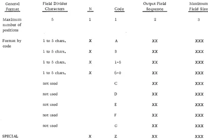
General Field Divider Output Field Maximum
Format Characters N Code Sequ~ Field Size
- - - -
-Maximum 5 1 1 2 3
number of positions
Format by 1 to 5 chars. X A XX XXX
code
1 to 5 chars. X B XX XXX
1 to 5 chars. X 1-5 XX XXX
1 to 5 chars. X 6-0 XX XXX
not used C XX XXX
not used D XX XXX
not used E XX XXX
not used F XX XXX
not used G XX XXX
SPECIAL X Z XX XXX
Each field divider must be followed by a record mark.
Figure 4. Field divider format summary chart
[image:31.615.88.508.138.421.2]Example
Sample Input
The following two data cards were converted from punched paper tape used in a
COl1G-munications message switching system:
1. ABCbCORPORATIONbbbXYZbTIREbCORPORATION050164
ORDERb1bGROSSb750-14bSUPERbDELUXEb051564YYYYMARY$
2. ABCbCORPORATIONbbbSMITHbPENCILbCOMPANY050164
ORDERb10bGROSSbNO. 2b51564XXXXXJ ANET*
Message Input Format
Input Field
1 - Sender
2 - Receiver
3 - Date
4 - Message
5 - Operator
Message Output Format
Output fields
1 - Input record length
2 - Sender field
3 - Receiver field
4 - Operator field
Contents of First Sample Record
ABC CORPORATION
XYZ TIRE CORPORATION
050164
ORDER 1 GROSS 750~14 SUPER DELUXE 051564
MARY
Source
This three-position field is optional, and includes the record mark, all characters, any blanks, and the groupmark in the entire input message. Any output field can be designated as the input record length field.
This field is from the first input field. This fixed-length field will be 25 poSitions in fixed-length, right-justified, with blank fill.
This is from the second input field. The output is to be 30 positions in length, right-justified, with blank fill.
This field identifies the operator who sent the message.
Output fields
l5 - Date field
Source
This is from the third input field and is six positions in length.
Control Card and Commentary for Example
Column Control
-:1 Y
2 Blank
:3 1
4: Blank
,-.) X
13-7 05
8-9 05
10-11 01
12 X
13 Blank
14 6
15-23 b3B02025:t=
Comments
Identifies control card
A second format card is not needed
Indicates card input
Single record input
Any nonblank entry, indicating sense switch A is to be used for the last card check
Indicates five input fields
Indicates five output fields, including the input record length field
Indicates that optional character count of input message length is desired, and that the count is to be in the first output field Indicates that an error tape is to be written containing those messages that could not be formatted according to the specifications given
Indicates no header label record. This applies only to tape files, and a card file is to be processed.
Output records to be padded with 9s so as to be a multiple of 6
This is the field identifying the sender of the message. End·-of-field identified by three or more blanks (b3B). This is to be the second output field, 25 positions long (02025). A record mark follows each field divider definition.
-27-Column Control
24-31 6F03030=t=
32-38 E05006:1=
39-54 2Z00500:l= X3BtY3B=t=
55-62 $lA 04010=1:
63
*
Sample Output Records
Comments
This is the receiver field, ending with the occurrence of six or more numeric characters belonging to the following field (6 F). This is the third output field, 30 positions long (03030).
This identifies the date field, exactly six positions long, equal to the length of the output field, and assigned to the fifth output field.
This is the input field containing the actual mess;3..ge. The basic Z statement indicates two alternatives (2Z), no output field specified (none desired), and an input length of up to 500 characters. The first alternative (X3B) indicates that the character X must appear three or more times. The other alternative (Y3B) is the same, except that the recurring character is Y.
This field is the operator identification field, identified as ending with a gr09P-mark appearing once ( 1A). It is to be the fourth output field, ten positions long (04010).
Field divider statements are terminated by a record mark. The end of the forrnat card is signaled by two successive rec-ord marks.
The following two output records were produced from the input based on the specifica-tions provided in the control card:
1. 093bbbbbbbbbbABCbCORPORATIONbbbbbbbbbbXYZbTffiEbCORPORATION
bbbbbb~ARY050164999*
2. 080bbbbbbbbbbABCbCORPORATIONbbbbbbbbbbS~THbPENCILbCO~PANY
Note that each record was padded with 9s so as to be a multiple of six. The field lengths in the output file are:
Input record length 3
Sender 25
Receiver 30
Operator 10
Date 6
Total 74
,
Padding 3 Groupmark 1
Record Length 78
Phase 1 Messages with Program Halt
F2 Number of input data fields defined not equal to count in columns 6-7
F3 Insufficient Zalternatives available
:F4 An output field sequence number is not numeric
:F5 Second format card indicated but not present
:F6 An output field sequence number is greater than the entry in columns 8-9
F7 Too many output fields specified in columns 8-'9. Cannot exceed number of input fields (6-7) plus one for message length field (10-11).
F8 Columns 6-7 not numeric, or contain 00
F9 Column 3, input type, not 1 or 2
FlO Incorrect field divider code. Incorrect code printed next to message.
F11 Output field definition missing. Sequence incornplete.
F12 Columns 8-9 not numeric, or contain 00
F13 Column 14 not numeric, or blank
-29·-F14 Number of alternatives for Z code other than 2 or 3
F15 A field size maximum is alphabetic, 00, or blank
F16 An n character is alphabetic or 0
F17 Blocked output requested, but calculated blocking factor not between 02 and 99, inclusive. Record size is less than 16 or more than 750 characters.
F18 Output record size greater than 999. The sum of all output field sizes must be less than 1000.
Phase 2 Messages
The following messages printed during phase 2 of the prograJn do not cause a pro-grammed halt (except F1). The associated error record may be printed in full or in part, or printing may be suppressed, according to the setting of sense switches D and E.
F1 Groupmark not used to identify last field. Format control card error. Tape unit 1 rewound and machine halted at position 3008. Correct control cards and restart job.
R1 Input card record exceeds 1000 characters
R2 Last card processed, last data record incomplete
R3 Groupmark found before format card specification tests were fully applied
CHAPTER 2: DATA MANIPULATION PROGRAMS
FIELD EDIT PROGRAM
This program will left- or right-justify the fields of a data tape produced by the input control program. Up to ten data fields may be defined for an alphabetic sort (left-justified), and up to fifteen fields for a numeric sort (right-justified).
The control card does not include the file specifications since these are already available in storage from the input control program.
!!,ield Adjustment
Fields are adjusted by repositioning them so that the left or rightmost character is other than a BCD blank character. Normally, left adjustment is used to align alphabetic fields for sorting, while right adjustment is used to align numeric fields for logical and arith-metic operations. The first part of the control card specifies fields to be left-adjusted, while the second part controls right adjusting. In the following examples, a lowercase b indi.cates a blank:
Left Adjustment
Alphabetic comparison or sorting require fields to be left-adjusted, with blank fill. For example:
Before bbbABC bbRSbT
Right Adjustment
After ABCbbb RSbTbb
Arithmetic and logical operations require right-adjusted fields, with either blanks or zeros for fill. For example:
Before b21886bbb b21886bbb
After bbbb21886 000b21886
(Blank fill) (Zero fill)
To completely zero-fill the high-order positions, the field should be specified for both left and right adjustment on the same control card, as in:
b21886bbb 21886bbb 000021886
Control Card Format
Column
1
2-3
4-5
6-7
8-9
10-11
12-13
14-15
16-17
18-19
20-21
22-23
24-25
26-29
30
31-32
33-34
Contents
E (control card identification)
Number of fields to be left-adjusted. If none, enter 00. Maxi-mum is ten (see note).
Field number of first data field to be left-adjusted as defined to the data input control program run that generated the input file must be blank if columns 2-3 contain 00. The entry 00 is invalid (see note).
Field numbers of the second through tenth input data fields to be left-adjusted (card columns 6-7 to 22-23). Use two columns per field. Columns should not be skipped. Unused columns are left blank. At least two blank columns must follow the last specified field number (see note).
Blank
Unused
Insert character. Must always be a zero or blank. This character will be used to fill the high-order position of fields when right adjusting a data field.
Number of fields to be right-adjusted. Maximum of fifteen fields. Enter 00 if none (see note).
37-38
39-40
41-42
43-4·4:
47-48
49-50
51-52
53-5·4:
55-56
57-58
59-60
61-6.2
63-64
65-79
80
Second through fifteenth fields to be right-adjusted. Follow specifications outlined for columns 4-23 (see note).
Blank
Unused
Input file disposition. Any value indicates input is to be saved. Blank indicates that input file is not to be saved.
~~: These fields must contain only the numerical characters from 0-9 with leading zeros. Field range is from 01 through 25.
CONTROL CARD ERROR LIST, CARD COLS 2--23
This is the heading for error messages pertaining to columns 2·-23, and will always be printed.
ERROR LIST, CC 30-62
This is the heading for error messages pertaining to columns 30-62, and will always be printed.
****MAX. VALID FIELD NO. IS XX****
xx
is the number of data fields per tape record as specified in the control card for the data input control program. It is always printed.TOO MANY FIELDS TO BE ADJUSTED, MAX. L-10, R-15
Card columns 4-25 and/or 33-64 have been used, thus requesting more than ten and/or fifteen data fields to be left/right-adjusted, respectively. This error message may appear under one or both of the above headings.
mv
ALID FIELD NO. IN CC#OXX/OYYOne (or both) of the character(s) at card columns XX and/or YY (YY=XX+1) is an alpha-betic or special character, 00, or a number greater than the number of data fields as specified in the system data input control program (which number was printed out as stated above). This is an error condition.
FIELD COUNT NOT EQ. TO NO. OF FIELDS TO BE ADJ.
The left and/or right field count(s), card columns 2-3 and 31-32, is not equal to the number of left/right card fields used which precede the required two blank card columns. This is an error condition.
CHARACTER IN CC 30 NOT ZERO OR BLANK
The insert character used when right adjusting a data field can only be either a zero or a blank. This is true even when there are no fields to be right-adjusted.
SAVE TAPE UNIT X READY NEW TAPE SAME UNIT - PRESS START
This message is printed as a result of card column 80 of the control card not being blank. It is not an error message.
This message, appearing below the two error list headings, indicates no control card errors, and the program will begin to adjust the specified data fields if the system error switch is not on.
****PREV. SYSTEMS ERROR - CONTROL RETURNED TO MONITOR***
CONTROL CARD INDICATES NO ADJ. REQD.
The left and right field counts, card columns 2-3 and 31-32, are both 00, columns 4-5 and 33-34 are blank, and column 30 is blank or contains a zero. This condition is not considered a control card error, though no data field adjustnlent is performed. Control is turned over to the system monitor.
Considerations
The start and end of program messages are printed on the IBM 1403 Printer. A CONTROL CARD message with a printout of the control card content is always printed by the program.
Card errors are noted, the program sets the system error switch on, completes
checking the entire control card, printing any other error messages, and then transfers control to the system. monitor. The program will not perforrn any data field adjust-ments.
Before execution of the program, either the monitor or the previously executed system program will read the field edit control card. The program, upon being read into storage, will begin to scan the control card for validity errors. An error message is printed for each error and a program error switch set. At the completion of the control card scan, the program error switch and the systems error switch are tested (see "System Rules for Operational Programs" for a description of the system error switch. The program switch indicates whether or not the control cards were acceptable to the program). If either is on, control is given to the monitor. If both are off,. a check is made to ensure that the left and right field counts (card colunms 2-3 and 31-32), are not both 00. If both are zero, control is given to the monitor; otherwise, the program continues.
SYMBOL SUBSTITUTION PROGRAM
Thi.s program provides a means of inserting specific values in user-designated data fields within a file of records produced by the data input control program.
Control cards used to locate records in the file contain two values, each up to 34 characters long. One is the current value used to locate designated records. The other value is used to replace the current value, or be inserted in another field of the records con.taining the current value.
The options provided are:
A. Insert a value in every record.
This may be used, for example, to insert a date or project number, or other constant value in each record when the file is to be merged with other files, but individual records must retain their source identity.
-35-B. Insert or substitute a value in selected records.
The finder value in the control card is used to select specific records. The neW or replacement value is either substituted for the current value or inserted in another field in the record.
C. Selectively replace values in a file containing several ascending sequences or strings of records. A new sequence is identified by a record with a value lower than that of the preceding record.
Three suboptions are available for this type of file:
Cl. Substitute the new value from the control card whenever a record in the input file contains the current value specified in the control card. The new value from a single control card may be entered in many successive records, as long as the control card current field equals the tape record current value. When a new sequence in the input is detected, or the current value in a file record is higher than the current value in the control card, a new control card is read in.
C2. This option is similar to Cl, except that the substitution is made only in the first matching record found by the program. A new control card is then read in.
This option provides the facility for modifying individual records in a file if the file sequence is lmown.
C3. This option is similar to C2, except that no substitution is made, and the first matching record is copied onto the output file. The next data record and control card are then read in.
By using two control cards, this option can be used to skip the first matching record and:
a. Option C2 used to insert a value in the second record, or
b. Option Cl used to insert a value in all matching records except the first.
Control Card Formats
Symbol Definition Control Card C
1
2
a-4
fi-6
1"1-9
10
11-46
41'-80
Contents
C (program identification)
C (control card identification)
Not used
Number of field in which the new value is to be inserted. This must be a number with any necessary leading zeros.
Not used
Input tape file disposition. Any character other than a blank indicates that the input tape is to be saved.
Unused
The constant value to be inserted. Value to be punched right-adjusted. Length should not exceed the data field in which the constant is to be inserted. Use leading (high-order) blanks or zeros as required to fill the receiving field.
SY1nboi Definition Control Card F
1
2
3-4
5-6
7-8
Contents
C (program identification code)
F (control card identllfication)
The number of the input record field that contains the current (old) value to be tested. This number must be the same on all C F control cards in anyone run (see note).
The number of the input record field in which the new value is to be inserted. This number must be the same on all CF control cards in anyone run (s ee note).
Sequence number. All CF control cards in a given run are assigned an arbitrary sequence number from 01-99 by the user. These columns are left blank to indicate the same sequence as the preceding control card. The first card of a new sequence must not be left blank (see note).
-37-9
10
11
12-45
46
47-80
Option control. Only the following values are valid:
Blank - substitution of new value is to be made in all data records containing the old value.
o -
do not change matching record. Copy it on output file, read next control card and next data record.1 - substitute new value in the first matching record, then read in next control card and data record.
Input file disposition:
Blank - do not save input tape.
Any other value - save input tape. If a CC card is not used, this must be on first C F card to save the input.
No match error indicator:
Blank - If a control card does not match a tape record, it is not to be treated as an error condition
Any other value - an unmatched control card is to be treated as an error condition
Old value to be located within the data file records. This value is also used for matching control cards and tape records. The value is punched right-aligned, and may consist of any BCD characters. The length of the value and the use of leading zeros or blanks must be consistent with the old value field in the tape record. The old value field number is in. columns 3 and. 4 of this control card.
Unused
New value to be substituted or inserted in the output record field indicated in columns 5 and 6 of this control card. The value is punched right-aligned, and may consist of any BCD
characters. The value should use high-order zeros or blanks so as to equal the length of the output field. This field shauld be left blank if card column 9 contains a zero (0).
Sequence Control
This program alters tape records only to the extent of inserting a new value in a specified field, or substituting the new value for the old or previous value.
The tape records are considered to be in ascending sequence according to the value in the old value field (columns 3-4). A sequence break in the data file is signaled by an old value lower than the old value in the previous record. This initiates a new sequence . in the file. \Vhen a control card indicates a continuation of a sequence (columns 7-8), and
the ta.pe file has a sequence break, a tape sequence error is assumed unless 'the "no rnatch" error indicator (column 11) is blank.
The following messages pertain to error conditions. Errors detected that would cause erroneous results are signaled by setting an error switch. Control card analysiS con-tinues, but program execution is suppressed. Setting the error switch establishes a "Don't Do" condition. This is preceded by:
eRewinding and unloading tape units 3 and 4
ePrinting a message indicating which tape un:it contains the input file to be saved
eSetting the system error switch
e Printing a message indicating the transfer of the Don't Do routine to check the remaining control cards. After the control cards have been checked, control is returned to the monitor instead of executing the program.
ERROR, CARD COLUMN 1, INVALID FIRST CARD
Character is :not a C. Card is listed. TRANSFER TO MONITOR message is printed (but not if error message is produced by Don't Do routine), and control is returned to the nlonitor program.
ERROR, CARD COLUMN 2, INVALID FIRST CARD
Character in column 2 .is not a C or F. Transfer to Don't Do routine.
ERROR, CARD COLUMN 2
Character is not a C or F. Card is listed. Transfer to Don't Do routine.
ERROR, CARD COLUMN 9
Char:acter is not a blank, 0, or 1. Card is listed. Transfer to Don't Do routine.
-39-ERROR, INVALID FIE LD NUMBER, CARD COLS. 3-6
Refer to explanation of these columns in control card format. Card is listed. Transfer to Don't Do routine.
ERROR. INVALID FIELD NUMBER CARD COLS. 7-8
Field is not all blank or numeric. Card is listed. Transfer to Don't Do routine.
EOF, NO MATCH FOR CARD
End-of-tape file has been reached with a CF control card still remaining in the card reader to be processed. Card is listed. This is repeated for each card if more than one card remains to be processed