Restricted Distribution
Field Engineering
Theory Of Operation
Th is manual is intended for internal use only and may not be
used by other than IBM personnel without IBM's written permissioh.
2260 Display Station, Models 1 and 2
2B4B Display Control, Models
I, 2,
and 3
(Serial
No.
SO,OOO Series)
tion of the IBM 2260 Display station Models 1 and 2, and IBM 2848 Display Control Unit, Models I, 2, and 3. However, the description of the 2848 Dis-play Control pertains only to those units whose serial numbers are 60,000 or above.
The following publications can be used to sup-plement the information provided in this manual: IBM 2260 Display Station, IBM 2848 Display
Control Maintenance Manual (Form Y27 -2047 -2)
IBM 2260 Display Station, IBM 2848 Display Control FE Diagram Manual (Form
Y27 -2048-2)
1052 Printer Keyboard and 1053 Printer Main-tenance Manual (Form 225-3179-2)
Medium Power Standard Power Supplies (Form 223-2799-0)
IBM 1052, 1053 CEMI (Form 225-3179) IBM System/360 I/O Interface - Channel to
Control Unit - Original Equipment Manu-facturers Information (Form A22-6843-3)
ABBREVIA TIONS LIST
The abbreviations used in this manual, together with their definitions, are as follows:
Abbreviation ACK
ASCII CAN CRT DAU DC DS EBCDIC EOM EOT
Definition Acknowledge
American Standard Code for Information Interchange Cancel
Cathode-Ray Tube Data Adapter Unit Display Control Display Station
Expanded Binary Coded Deci-mal Interchange Code
End of Message End of Transmission
changes released in the following F. E. Supple-ments:
Form Number Y27-2165-0
Y27-2171-0
Abbreviation
EPO ETX FC LF LRC MI NAK
NDC
NL OLSA SMS SOH STX VRC XA
Pages Affected 4-10, 4-11 and 4-18
v through vii, 1-3 through 1-6, 1-21,1-22,2-97, 2-98,2-123, 2-124,2-125, 2-126, 6-1 through 6-4, B-1 through B-3, X-I through X-8 add pages 2-124A and 2-124B
Date
Sept. 11, 1967
Dec. 1, 1967
Definition
Emergency Power Off End of Text
Feature Code Line Feed
Longitudinal Redundancy Check Manual Input
Not Acknowledge Nondestructive Cursor New Line
Off Line Selectric Analyzer Standard Modular System Start of Heading
Start of Text
Vertical Redundancy Check Transmit Adapter
This manual has been prepared by the IBM Systems Development Division Product Publications, Dept. S20, CPO Box 120, Kingston, N. Y., 12401. Address comments concerning the manual to this address.
@
International Business Machines Corporation 1967CHAPTER 1 INTRODUCTION. Scope of Manual •
IBM 2848 Display Control, General Description IBM 2848 Display Control, Model 1 IBM 2848 Display Control, Model 2 IBM 2848 Display Control, Model 3 IBM 2848 Model Summary • Special 2848 Features
Operator Controls and Indicators CE Panel
IBM 2260 Display Station, General Description Special Features •
Feature 4766 Alphanumeric Keyboard Feature 4767 Numeric Keyboard Control Key Functions
Functional Description •
IBM 2848-2260 Display Complex IBM 2848 Display Control
Channel Adapter • IBM 2848 Common 1053 Printer Adapter Control and Timing IBM 2260 Display Station
System/360 - Channel Adapter Interface General •
Line Description Bus Out • Bus In
Operational Out Request In • Address Out Select Out Hold Out Select In Operational In Address In • Command Out Status In. Service Out Service In • Suppress Out Clock Out • Metering In • Metering Out Addressing •
Commands and Command Operation. Write DS Buffer Storage Command Write 1053 Buffer Storage Command Write DS Line Address Command. • Read DS MI (Manual Input) Command Short Read DS MI Command • Read Full DS Buffer Command No Op (No Operation) Command Erase DS Buffer Storage Command Sense Command •
1-1 1-1 1-1 1-2 1-2 1-3 1-3 1-3 1-3 1-3 1-3 1-6 1-6 1-6 1-6 1-6 1-6 1-8 1-8 1-11 1-12 1-13 1-13 1-14 1-14 1-14 1-14 1-17 1-17 1-18 1-18 1-18 1-18 1-19 1-19 1-19 1-19 1-19 1-20 1-20 1-20 1-20 1-21 1-21 1-21 1-21 1-22 1-22 1-23 1-23 1-24 1-25 1-25 1-25 1-25
I
Form Y27-2046-2, -3 FES Y27-2190
Test I/O Command • Interleave Read
Channel-Display Complex - Sequence and Responses Stop Sequence •
Interface Disconnect Sequence Selective Reset Sequence
Read Operation Write Operation System Reset Sequence
Short Control Unit Busy Sequence. Sense and Status Bytes
Sense Byte • Status Byte
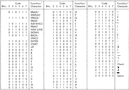
Character Codes and Displayable Symbols Displayable Symbols
EBCDIC Code • Keyboard Code
Internal 2848 Six-Bit BCD Code 1053 Printer Code.
Terms and Definitions
CHAPTER 2 FUNCTIONAL UNITS Introduction
IBM 2260 Display Station Cathode-Ray Tube
Eelctron Gun Beam Focusing
Deflection Yoke Assembly Raster
Correction Magnets • Centering Rings Tilting Aquadag Coating Screen Phosphors CRT Electrode Potentials
CONTENTS 1-25 1-25 1-26 1-26 1-26 1-26 1-26 1-26 1-26 1-27 1-27 1-27 1-27 1-28 1-28 1-29 1-30 1-30 1-31 1-31 2-1 2-1 2-1 2-3 2-4 2-4 2-5 2-5 2-5 2-5 2-5 2-6 2-6 2-7 Display Station Electronics for DS Using Older Level Circuit Boards
Video Amplifier Sync Clipper
Horizontal Multivibrator Vertical Phase Detector Vertical Multivibrator Vertical Output Circuit High-Voltage Rectifier Damper Circuit
Display Station Electronics for DS U sing Tube Adapters
Display Station Electronics for DS Using Newer Level Circuit Boards
Display Station Power Supply
B+ Supply for DS U sing Older Level Circuit Boards
B+ Supply for DS Using Newer Level Circuit Boards
-84VDC Supply +48VDC Supply
2-7 2-7 2-8 2-8 2-11 2-11 2-12 2-12 2-12 2-13 2-13 2-13 2-14 2-14 2-14 2-14
Display Station Timing
Organization of Basic Delay Line Slot Vertical Sweep Timing •
Horizontal Sweep Timing Manual Input Keyboard
D escri pti on • Keyboard Mechanics
Bail Contacts • Keystem Contacts
Keyboard Restoring Components Keyboard Interlocks
Keyboard Electronics. IBM 2848 Display Control
Display Adapter Delay Line Theory
Description • Operation
Delay Line Bit Organization. Buffer Slot Layout
Delay Line Controls BCD Data Gating • Video Data Gating Keyboard Operation
Keyboard Priority Keyboard Controls
Keyboard Data Bit Conversion and Gating Timing and Clock Circuits •
Oscillator
A and B Delay Pulse Circuit Bit Ring Counter •
Even-Odd Display and Late Triggers Buffer Parity Control Circuit Row Counter
Segment Counter
Character Display Colunm Ring Counter Line Counter
Sync Generator
Vertical Sync Generation Horizontal Sync Generation Horizontal Blanking Sync Pulse Delay Circuit Reset Controls • TIC Sample Decoder
General • Circuit Operation BCD Gating Outputs
Character Generator Read Gate Generation. Display Addressing
General •
Address Encoder and Address Register Display Group Decoder •
Display Address Decoder TIC Found Latch • Write A and Write B Latches
Keyboard Write Operation Erase Operation
Interface Write Operation TIC Write and Erase Operation
ii (3/68)
" 2-14E 2-14 2-17 2-17 2-17 2-18 2-18 2-18 2-24 2-24 2-25 2-25 2-27 2-29 2-29 2-29 2-29 2-30 2-31 2-35 2-35 2-35 2-36 2-36 2-36 2-40 2-40 2-43 2-45 2-45 2-47 2-47 2-50 2-50 2-52 2-52 2-54 2-54 2-56 2-56 2-56 2-57 2-57 2-57 2-60 2-62 2-62 2-62 2-62 2-63 2-63 2-65 2-65 2-65 2-66 2-66 2-69 2-69
Write EOM (NDC Only) • Other Write Latch Control Signals. Serializer.
Write Data Operation Write TIC Operation Other Write Operations Deserializer •
Common Buffer Register Common Buffer Register Inputs
Sense Amplifier Inputs End of Message Inputs. Keyboard Inputs Interface Inputs Delay Line Inputs Reset Inputs
Common Buffer Register Outputs Register Control
Set EOM
SOM, New Line, and EOM Decode Character Generator
Core Plane • Cell Selection
Read Winding Connection and Operation Sense Winding Connection and Operation Binary Data Outputs
Decoders. W rite Control Read Control
Position Storage and Compare Logic General •
Counter Storage Control • Row Counter Storage and Compare Segment Storage and Compare Column Storage and Compare • Line Counter Storage and Compare Display Compare •
Left/Right Storage Buffer Selection Circuits Video Buffer Selection
Nondestructive Cursor Generation. W rite Line Address
Command Decode Decoder Operation Keyboard Command Decode Parity Control •
Parity Assignment • Parity Update • Parity Check Parity Write Control Parity Read Gate Control Printer Adapter Controls • Control Latches and Triggers Channel Adapter •
Block Diagram Analysis Out Tag Delays
Cha1ll1el Request • • Control Unit Request • Status Request Service Request Operational In Latch Busy Latches. •
Interface Busy Device Busy. Address In Status In Service In • Stack Status Latch Stop Latch • •
Remember End and Local- Remote Latches Command Chaining and Inhibit Attention Latches.
Command Chaining • Inhibit Attention • Disc01ll1ect and Reset Circuits Hold Select Circuits •
Control Unit and Device Addressing Channel-Originated Address Control Unit-Originated Address Printer Address.
Manual Address Command Decode Sense and Status Registers
I/O Request and Character Register Control I/O Request
Character Register Control • Character Register and Code Converter •
Character Formats Start Symbol New Line Symbol Check Character • Circuit Description
Cha1ll1el Adapter Operational Sequences Cha1ll1el-Initiated Sequences •
Sense. Erase. No Operation Test I/O. •
Command-to-Busy Device • Control U nit Busy
Control-Unit-Initiated ~equences. • Data Transfer •
Sense Transfer • Status Transfer Special Sequences
Stack Status Stop • • Printer Adapter
Printer Adapter Circuit Description Ring Counter •
Print In Buffers Print In Buffer 1 Print In Buffer 2 Case Change Check Parity Assignment • Delay Line. •
2-117 2-117 2-117 2-117 2-117 2-118 2-118 2-118 2-118 2-118 2-119 2-119 2-119 2-119 2-121 2-121 2-122 2-122 2-122 2-125 2-125 2-126 2-126 2-126 2-126 2-129 2-131 2-131 2-131 2-132 2-132 2-133 2-133 2-133 2-133 2-133 2-133 2-137 2-138 2-138 2-138 2-139 2-140 2-141 2-141 2-143 2-145 2-146 2-146 2-146 2-147 2-148 2-148 2-149 2-149 2-149 2-150 2-150 2-150
Form Y27-2046-2, -3 FES Y27-2190
Parity Check Circuit • Print Out Buffer. FWlction Decoder Keyboard Print Operation
Printer Adapter Input Operation
Printer Operation, Case Change Not Required. Printer Operation, Case Change Required EOM and Display Adapter Parity Check • Print Cycle Operations •
Print Cycle and No Parity Check Print Cycle with Parity Check
Print Cycle with EOM and Chk Chac Latch On. Print Cycle with EOM Set and Chk Chac Latch Off
Write 1053 Buffer Storage
CHAPTER 3 PRINCIPLES OF OPERATION General
Channel Adapter Operational Sequences Cha1ll1el-Initiated Sequences
Read or Write Selection Sense
Erase No Operation Test I/O
Command to Busy Device Control Unit Busy •
Control-Unit-Initiated Sequences. Data Transfer •
Sense Transfer. • Status Transfer • Special Sequences
Stack Status Stop • • • Keyboard Operations
Alphanumeric Key New Line Key • Up and Down Keys
Advance Key (NDC Feature)
Advance Key (Destructive Cursor Feature) Start Key
Enter Key Backspace Key Erase Key Print Key
CHAPTER 4 FEATURES Introduction •
Remote Interface Adapter General. •
ASCII Code Set
IBM 2701 Data Adapter Unit Data Sets
ASCII Communications Control Characters 2848 Display Control Modes of Operation
Control Mode • Text Mode • • • • 2848 Display Control Status
2-150 2-151 2-151 2-151 2-151 2-152 2-152 2-152 2-159 2-159 2-159 2-159 2-159 2-159 3-1 3-1 3-1 3-1 3-1 3-1 3-2 3-2 3-2 3-2 3-3 3-3 3-3 3-4 3-4 3-5 3-5 3-5 3-6 3-6 3-7 3-7 3-8 3-8 3-8 3-10 3-10 3-11 3-11 4-1 4-1 4-1 4-2 4-2 4-2 4-2 4-4 4-4 4-4 4-4 4-5
Transmit Status Selected Status Nonselected Status Receive Status Addressing Sequence
Commands and Command Operation Specific Poll to a 2260 Display Station Specific Poll to the 1053 Printer General Poll
Read Addressed Full DS Buffer. Write Addressed DS
Erase/Write Addressed DS Write Printer
Printer Request Condition Write DS Line Address
Summary of Sequences and Responses 2848 Display Control Sequences and Responses Channel Sequences and Responses
Functional Units Adapter Data Flow
Write Operation Read Operation Ring Counter
1.2-kc Clock and Serdes Control
S erializer- D eserializer Register. Serdes Data Inputs
Serdes Data Outputs Special Serdes Outputs Register Operation Character Register
Control Mode Operation. Write Operation
Read Operation Address Register
Write/Channel Initiated Read Operation Read Manual Input Operation
Command Decoder ASCII Command Decoder ASCII Command Coder • LRC Register
LRC Operation During Write LRC Operation During Read Parity Check and Assignment •
Parity Assignment Parity Check
Serializer and 7-to-6-Bit Code Converter Character Register Inputs
Common Buffer Register Inputs Special Character Inputs Read and Write Mark Inputs Delay Line.
Deserializer and Output Register Deserializer
Address Transfers to Output Register Output Register Empty Latch Write and Write Command Controls Read and Read Command Controls 1053 Printer Controls
iv (3/68)
4-5 4-5 4-5 4-5 4-5 4-6 4-6 4-8 4-10 4-10 4-12 4-13 4-13 4-14 4-15 4-16 4-17 4-18 4-19 4-19 4-19 4-21 4-21 4-21 4-21 4-22 4-22 4-22 4-22 4-22 4-23 4-23 4-23 4-23 4-23 4-23 4-24 4-24 4-24 4-25 4-25 4-25 4-26 4-26 4-26 4-26 4-26 4-27 4-27 4-28 4-28 4-28 4-28 4-29 4-29 4-29 4-29 4-29
Theory of Operation • General •
Addressing Sequence - Write Operation Channel Response - SOH, EOT Character
Channel Response - DC AAddress
Channel Response - 2260 DS Address Command - Write Addressed DS • Remote Interface Response - ACK Character Channel Response - STX Character • Channel Response - Text Character • Delay Line Readout - Write Operation
Deserializer and OutPllt Register Transfer - Write Operation
Channel Response - ETX Character Channel Response - LRC Character Channel Response - EOT Character Command - Write Printer
Address Sequence Initial Adapter Response
Printer Ready and Not Busy • Printer Busy
Data Transfer
Address Sequence - Read Operation Command - Specific Poll to 2260 DS 2848 DC Response - STX Character • 2848 DC Response - 2260 DS Address 2848 DC Response - Text Character. Delay Line Readout - Read Operation
Deserializer and Output Register Transfer - Read Operation
Output Register to Character Register Transfer 2848 DC Response - ETX Character • Buffer Parity Check - Read Operation 2848 DC Response - LRC Character •
Channel Response - 5TX to Read End Sequence Write DS Line Address
Write/Erase Command
Write Erase Command - Channel Response (STX). General Poll
CHAPTER 5 POWER SUPPLIES AND CONTROL I ntroducti on
60-Cyc1e Power System Initial Power Distribution Power Control Sequences
Power On - Remote Power On - Local • Power Off - Remote Power Off - Local • Emergency Power Off Fault Condition Operation
Circuit Breaker Open During Local Operation Circuit Breaker Open During Remote Operation
Overtemperature Conditions DC Power Supply •
SO-Cycle Power System Initial Power Distribution Power Control Sequences
Power On - Remote Power On - Local • Power Off - Remote • Power Off - Local • Emergency Power Off Fault Condition Operation
Circuit Breaker Open During Local Operation Circuit Breaker Open Dur,ing Remote Operation
Contactor PK1 Overload Contacts Open in Local
Contactor PK1 Overload Contacts Open in Remote.
Reset of PK1 Overload Contacts Overtemperature Conditions Thermal Circuit Reset • DC Power Supplies
CHAPTER 6 CONSOLE AND MAINTENANCE FEATURES
Introduction
Controls and Indicator Functions
2848 Display Control, Operator's Panel 2848 Display Control, CE Panel • 2260 Display Station
Operating Control Alphanumeric Keyboard
Frontispiece IBM 2260 Display Station - 2848 Display Control •
1-1 1-2 1-3 1-4 1-5 1-6 1-7 1-8 1-9 1-10 1-11 1-12 1-13
SummarY of IBM 2848 Display Control Models • •
IBM 2848 Display Control Features (2 Sheets)
Optional Alphanumeric Keyboard for
2260 DS • • • • •
Optional Numeric Keyboard for 2260 DS
IBM 2848 - IBM 2260 Display Complex, Block Diagram •
IBM 2848 - IBM 2260 Block Diagram. • Timing and Clock Circuits, Simplified Block Diagram •
CRT Display Organization • 2260 Display Station, Block Diagram. Typical Address Assignments, Model 1 2848 DC.
Commands and Their Code Structure. •
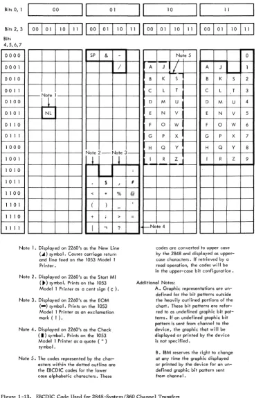
Displayable Symbols • • • • • •
EBCDIC Code Used for 2848-System/360 Channel Transfers •
5-8 5-8 5-8 5-8 5-8 5-8 5-8 5-8 5-8 5-9 5-9 5-9 5-9 5-9 6-1 6-1 6-1 6-1 6-1 6-1 6-1 6-2 viii 1-3 1-4 1-7 1-7 1-8 1-9 1-11 1-15 1-17 1-21 1-22 1-28 1-29 1-14 1-15 1-16
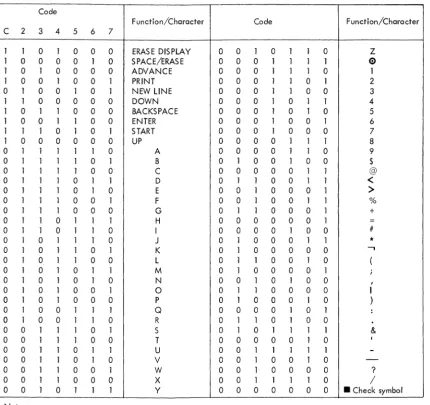
Keyboard Code. 1-30
1-17 2-1
Internal 2848 Six-Bit BCD Code 1-31
1053 Printer Tilt-Rotate Codes and Their
2848 Six-Bit BCD Code Equivalents. 1-32
Terms and Definitions (2 Sheets) 1-33
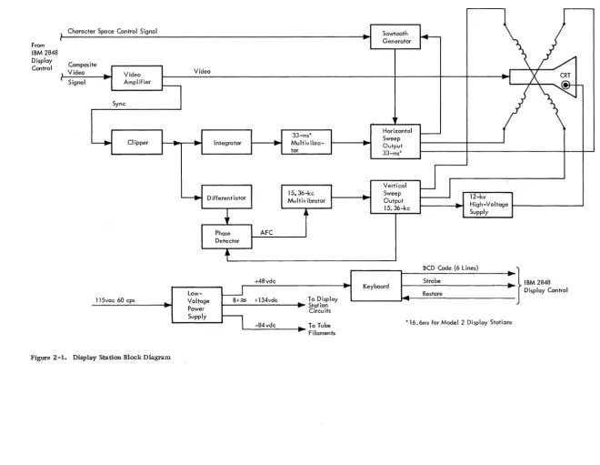
Display Station Block Diagram 2-2
Form Y27-2046-2, -3 FES Y27-2190
Numeric Keyboard Control Key Functions
APPENDIX A MACHINE CHARACTERISTICS. •
APPENDIX B SPECIAL CIRCUITS Introduction
Integrator Card A, Type FYM Integrator Card B, Type FYN
Four Diode-Coupled 3-Way AND Circuit, Type FZK. Video Mixer, Type EFY. •
Sense Gate and Output Sense Level, Type FYZ Reed Relay, Type FYF •
Reed Relay, Type YPM •
APPENDIX C LANGUAGE FEATURES Feature Description • •
Identification and Instruction Label Changes Character Codes • •
Character Generator Modification 1053 Printer Print Element Keyboard Changes
French Keyboard • • German Keyboard United Kingdom Keyboard
INDEX 6-2 6-2 A-1 B-1 B-1 B-1 B-1 B-1 B-1 B-2 B-3 B-3 C-1 C-1 C-1 C-1 C-1 C-1 C-1 C-1 C-1 C-2 X-1 ll..LUSTRATIONS
2-2 Composite Video Signal (One Vertical
Scan) 2-3
2-3 Cathode-Ray Tube 2-3
2-4 CRT Electron Gun 2-4
2-5 Deflection Coil Currents and Raster
Relationship 2-6
2-6 Persistence Characteristics of P4 and P39
Phosphors 2-7
2-7 Display Station, Electrical Schematic
Diagram for DS Using Older Level
Circuit Boards 2-9
2-7A Display Station Electrical Schematic
Diagram for DS Using Tube Adapters 2-14A
2-7B Display Station Electrical Schematic
Diagram for DS Using Newer Level
Circuit Boards 2-14C
2-8 Display Station, Power Supply For
50-Cycle Operation 2-14E
2-9 Display Station Timing •
. .
2-152-10 AlphanumeriC Keyboard, Bottom and
Rear Views •
.
2-192-11 Key Position 2-20
2-12 Permutation Bar and Keyboard Latch
(Normal) 2-20
2-13 Permutation Bar and Keyboard Latch
(Tripped) 2-20
2-14 Keystem Numbering Chart • 2-21
2-15 Keystem Number and Bail Selection For
Alphanumeric Keyboard 2-22
2-16 2-17 2-18 2-19 2-20 2-21 2-22 2-23 2-24 2-25 2-26 2-27 2-28 2-29 2-30 2-31 2-32 2-33 2-34 2-35 2-36 2-37 2-38 2-39 2-40 2-41 2-42 2-43 2-44 2-45 2-46 2-47 2-48 2-49 2-50 2-51 2-52 2-53 2-54 2-55 2-56 2-57 2-58
vi (3/68)
Keystem Number and Bail Selection for Numeric Keyboard
Key Position (Latched and Tripped) • Interlock Disks
Interlock Disks (Partial) • Keyboard Electronics
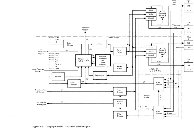
Keyboard Data Transfer Timing Display Control, Simplified Block Diagram
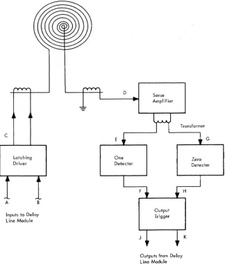
Delay Line Module
Delay Line Module, Simplified Block Diagram
Delay Line Timing Buffer Slot Layout
Delay Line Controls and BCD-Video Gating
Delay Line Control Timing Delay Line Timing, One Slot Keyboard Assignments for Model 3 Machines
Keyboard Priority
Keyboard Controls and Keyboard Data Bit Conversion and Gating •
Timing and Clock Circuits, Simplified Block Diagram •
Oscillator and A-B Delay Pulse Circuit Bit Ring Counter •
Even-Odd Display Trigger Circuit Buffer Parity Control Circuit Row Counter
Segment Counter
Character Display Column Ring Counter. Line Counter
Sync Generator Sync Generator Timing Sync Pulse Widths. Reset Controls •
TIC Sample Time Decoding
TIC Sample Decoding, Buffer 1 and 2 • Function of TIC Sample Decoder Circuit Groups
Use of .Character Column Outputs as Character Generator Read Gates • Display Addressing
Address Encoder Outputs. • Write A and Write B Latches, Timing Chart
Write A and Write B Latches
Even and Odd Display Signals, Timing Chart
Serializer, A Delay Serializer, B Delay
Serializer Data and Inputs and Even-Odd
Bit Sequences. • • •
Deserialization of Delay Line Data at
CBR Inputs. • • • •
2-23 2-24 2-25 2-25 2-26 2-27 2-28 2-30 2-31 2-32 2-33 2-37 2-39 2-41 2-43 2-43 2-44 2-45 2-46 2-48 2-49 2-49 2-50 2-51 2-52 2-53 2-55 2-56 2-56 2-58 2-59 2-61 2-62 2-63 2-64 2-65 2-66 2-67 2-70 2-71 2-72 2-73 2-74 2-59 2-60 2-61 2-62 2-63 2-64 2-65 2-66 2-67 2-68 2-69 2-70 2-71 2-72 2-73 2-74 2-75 2-76 2-77 2-78 2-79 2-80 2-81 2-82 2-83 2-84 2-85 2-86 2-87 2-88 2-89 2-90 2-91 2-92 2-93 2-94 2-95 2-96 2-96A 2-97 2-98 2-99 2-100 2-101 2-102 2-103
Common Buffer Register
Common Buffer Register Input Signals Common Buffer Register Controls • SOM, New Line, and EOM Decode Circuit
Common Buffer Register Control Codes Character Generator, Block Diagram. Character Generator Timing
Core Plane Layout and Cell Selection Selection, Read, and Sense Winding Connections
Generation of Binary Data from Memory
Cell • • • •
Low Order Decoder and Driver • Character Generator Write Control Character Generator Read Control
Circuits •
Function of Position Storage Circuits • Counter Storage Control. • Counter Storage Control Outputs • Row Counter Storage
Vertical Segment and Column Storage on Compare
Generation and Purpose of Save Line Counter Signals
Buffer Selection and Display Compare Video Buffer Selection, A delay • Video Buffer Selections for A Delays. Nondestructive Cursor Generation. Display of NDC Cursor - Even and Odd Write DS Line Address Decode and Gating
Write Line Address Decoder Operation • Keyboard Command Decoder and Command Latches
Parity Circuits. • Printer Adapter Controls •
Control Latches and Trigger Functions (3 Sheets)
Channel Interface Controls • Out Tag Delays
Address In Latch • • Status In Latch •
Remote End, Local-Remote
Command Chaining, Inhibit Attention Disconnect and Reset
Hold-Select Circuit for Units not Equipped with Isolation Feature
Hold-Select Circuit for Units Eqnipped with Isolation Feature.
Control Unit and Device Addressing • • Command Byte Format
Command Decode I/O Request.
Character Register Control • Character Register Bits 0-3. • Character Register Bits 4-7 •
2-104 2-105 2-106 2-107 2-108 2-109 2-110 2-111 2-112 2-113 2-114 2-115 2-116 2-117 4-1 4-2 4-3 4-4 4-5 4-6 4-7 4-8 4-9 4-10 4-11 4-12 4-13 4-14 4-15 4-16 4-17 4-18 4-19 4-20 4-21 4-22 4-23 4-24
Channel-Initiated Selection (Read or Write)
Sense Operation Erase Operation No Op Operation Test I/O Operation Test I/O To Busy Device Control U nit Busy Sequence. Control Unit Initiated Data Transfer (Read or Write)
Sense Transfer • Status Transfer Stack Status Sequence Stop Sequence •
Printer Adapter, Simplified Block Diagram
Printer Adapter, Logic Diagram (3 Sheets)
Remote Display Complex Configuration. ASCII-8 Code Set.
Ten-Bit Format of Transmitted ASCII Characters •
Typical Remote Device Address Assign-ments
2848-2260 Commands (Remote) • Sequence/Response Diagram - Specific Poll to 2260 DS
Sequence/Response Diagram - Specific Poll to Printer •
Sequence/Response Diagram - General Poll
Sequence/Response Diagram - Read Addressed Full DS Buffer
Sequence/Response Diagram - Write Addressed DS • • •
Sequence/Response Diagram - Erase/ Write
Sequence/Response Diagram - Write
Printer • • • •
Sequence/Response Diagram - Line Address Write
Display Line Addresses (Remote) • Remote Interface Adapter, Data Flow Diagram
Command Decoder Function Codes • Character Register Control. • • Channel Response - SOH-EOT and DC Address Characters
Channel Response - Device Address Character
Channel Response - Command Character 2-136 2-137 2-138 2-139 2-140 2-141 2-142 2-143 2-144 2-145 2-147 2-148 2-149 2-153 4-1 4-3 4-4 4-5 4-6 4-7 4-8 4-9 4-11 4-12 4-14 4-15 4-16 4-17 4-20 4-24 4-31 4-32 4-33
Decode • 4-35
Remote Interface Response - ACK
Character 4-36
Channel Response - STX Character 4-37
Channel Response - Text Character 4-39
Delay Line Readout Control (2 Sheets) 4-40
4-25 &-26 4-27 4-28 4-29 4-30 4-31 4-32 4-33 4-34 4-35 4-36 5-1 5-2 6-1 6-2 6-3 6-4 6-5 6-6 6-7 B-1 B-2 B-3 B-4 B-5 B-6 C-1 C-2 C-3 C-4 C-5 C-6 C-7 C-8 C-9 C-lO C-ll C-12
Channel Response - ETX and LRC Character
Write Printer Control. • Specific Poll Command Decode • I/O Request Control •
2848 DC Response - STX Character 2848 DS Response - Device Address Read Operation - Common Buffer to Serializer Transfer
2848 DC Response - ETX Character • Read Operation - Buffe!: Parity Check Control
2848 DC Response - LRC Character Write/Erase Command •
General Poll Operation (2 Sheets) • 60-Cycle Power Distribution and Control (2 Sheets)
50-Cycle Power Distribution and Control (3 Sheets)
Operator's Panel - IBM 2848 CE Panel - IBM 2848
2848 Display Control Operator's Panel Controls and Indicators •
2848 Display Control CE Panel Controls and Indicators. •
2260 Display Station Alphanumeric
4-42 4-44 4-47 4-48 4-49 4-50 4-52 4-54 4-55 4-56 4-58 4-60 5-2 5-5 6-1 6-2 6-3 6-4
Keyboard 6-5
2260 Display Station Numeric Keyboard. 6-5
Function of 2260 DS Control Keys (2
Sheets) • • 6-6
Integrator Card A, Type FYM • B-1
Four Diode Coupled 3-Way AND Circuit,
Type FZK B-2
Video Mixer, Type EFY • B-2
Output Sense Level and Sense Gate,
Type FYZ B-3
Reed Relay, Type FYF • B-3
Reed Relay, Type YFM. B-3
Identification and Instruction Label
Summary C-2
Language Feature Character Codes C-3
1053 Printer Typehead, Language Symbol and Character Variations
Graphic Character and Function Key Change Summary. •
French Alphanumeric Keyboard French Numeric Keyboard • Keystem Number and Bail Selection, French Alphanumeric Keyboard German Alphanumeric Keyboard • • German Numeric Keyboard
Keystem Number and Bail Selection, German Alphanumeric Keyboard • United Kingdom Alphanumeric Keyboard
United Kingdom Numeric Keyboard •
C-3 C-3 C-4 C-4 C-5 C-5 C-6 C-6 C-7 C-7
ll)
SCOPE OF MANUAL
This manual describes the capabilities and the theory of operation of the IBM 2260 Display Station and the IBM 2848 Display Control (see Frontispiece).
The manual is divided into six chapters and three appendices:
1. Chapter 1, Introduction, provides a func-tional description of the equipment, including the major data flow and control signal paths. It also includes a description of the interface of the 2848 with System/360, a description of the feature structures of the 2848 and 2260, and reference data (code sets, command structure, etc.) required for an overall con-cept of equipment operation.
2. Chapter 2, Functional Units, gives a detailed description of the operation of the logic areas of both the 2260 and 2848, with simplified logic diagrams and timing charts.
3. Chapter 3, PrinCiple s of Operation, pre sents the theory of operation for the IBM 2848 Dis-play Control through the use of a compre-hensive set of flow charts.
4. Chapter 4, Features, presents the theory of operation of the remote interface adapter used in remote applications.
5. Chapter 5, Power Supplies and Control, ex-plains the operation of the IBM 2848 Display Control power supply, control, and distri-bution network. (Because of its integral relation with other display station circuitry, the IBM 2260 power network is discussed in Chapter 2.)
6. Chapter 6, Console and Maintenance Features, describes the function of the controls and in-dicators located on the operator and CE panels of the IBM 2848 Display Control.
7. Appendix A, Machine Characteristics, sum-marizes equipment capabilities and charac-teristics.
8. Appendix B, Special Circuits, describes the special circuits found in the 2848 Display Control.
9. Appendix C, Language Features, describes the language features available with the 2260 Display station.
There are three models of the IBM 2848 Display Control: Models 1, 2, and 3. This manual describes the operation of Model 3, which is the largest (in terms of the number of characters displayed) and the most complex. Once Model 3 operation is
un-CHAPTER 1. INTRODUCTION
derstood, the operation of Models 1 and 2 will be apparent. When the manual is used as reference material by those interested in Model 1 or 2 only, information unique to the Model 3 can be disre-garded.
Similarly, the IBM 2260 Display Station can be used as an output-only device when it does not include either of the two input keyboards (numeric and alphanumeric) that are available as special features. Throughout this manual it is assumed that the 2260 includes an input keyboard, so that the 2260' s full I/O capabilities can be described. When the manual is used as reference for output-only display stations (no keyboard), all data pertaining to keyboard input operations can be disregarded. The output capability (video display) is functionally separate from keyboard input operation.
Other features such as the printer adapter, channel adapter, and destructive and nondestructive cursor have been incorporated within the frame-work of the Functional Units chapter to permit a thorough analysis of the more comprehensive Model 3 tied to an IBM System/360 via the channel adapter. Although some of the features could have been placed in Chapter 4, certain advantages do accrue with the method selected. The interrelationships between the features and the adapters become more apparent when viewed and discussed on an overall systems basis rather than separated individually. As other features or optional equipment become available, they will appear in Chapter 4, Features.
IBM 2848 DISPLAY CONTROL, GENERAL DESCRIPTION
The IBM 2848 Display Control contains the storage and control logic required to interface the 2848 with either a System/360 selector or multiplexor channel or a communications data set. (The latter configuration permits remote operation of the dis-play group.) The IBM 2848 Disdis-play Control can also control up to 24 IBM 2260 Display Stations. The 2848 Display Control is available in three basic models; each can be supplemented by certain features to expand its basic display capabilities and to provide the display control with special functional abilities. The 2848 Display Control is described in the following paragraphs by first considering the capabilities of the three basic models and the feature combinations that can be selected to supplement each model. Then each feature is described in respect
All three 2848 models offer a choice of operating voltages (primary input of 208vac or 230vac) and exterior cabinet colors (red, yellow, blue, or gray, to permit aesthetic compatibility with the host System/360). These options are not discussed in respect to each model, however.
IBM 2848 Display Control, Modell
The basic IBM 2848 Model 1 is capable of operating two 3355 Display Adapters; each 3355 can service two IBM Model 2 2260 Display Stations. The Modell can generate a display that consists of six rows, each containing 40 characters (240 characters total), on the CRT of all 2260 Display Stations associated with the display control. The basic Model 1 also includes a choice of the 9011 Channel Adapter, the 9012 Data Set Adapter (1200 bps), or the 9013 Data Set Adapt-er (2400 bps) for intAdapt-erfacing with the host System/ 360.
Through incorporation of additional optional features, 2848 Model 1 capabilities can be extended to include the following:
1. The ability to drive six additional 3355 Dis-play Adapters (via 3857 Expansion Panel), four additional 3355's (via 3858 Expansion Panel, or ten additional 3355's (via 3857 and 3858). A maximum of 24 IBM 2260 Dis-play Stations (Model 2), each disDis-playing a 240-character (maximum) message, can thus be accommodated.
2. The ability to drive the 7927 Printer Adapter, which controls an IBM 1053 Model 4 Printer, to provide a permanent record of display group data under either program or operator control.
3. A nondestructive cursor (character-entry and display-position indicator and locator) that can be moved within the display area without disturbing or destroying the data displayed on the CRT of the 2260 Display Station.
4. A line-addressing feature which enables the processor, during write operations, to select anyone of the six lines within the 2260 Dis,"" play Station CRT display under program con-trol. '
5. A Foreign Language feature that equips the 2848 Display Control with the character set and operator control designations in the languages of France, Germany, and United Kingdom.
1-2 (4/67)
Display Adapter which services two IBM Model 2 2260 Display stations. The Model 2 can generate a display consisting of 12 rows, each containing 40 characters (480 characters total), on the CRT of all 2260 Display Stations associated with the dis-play control.
The basic Model 2 also includes a choice of the 9011 Channel Adapter, the 9012 Data Set Adapter (1200 bps), or the 9013 Data Set Adapter (2400 bps) for interfacing with the host System/360.
other optional features can be selected to extend the capabilities of the basic Model 2. These ex-tended capabilities include:
1. The ability to drive three additional 3356 Display Adapters (via 3858 Expansion Panel), four additional 3356 Display Adapters (via 3857 Expansion Panel), or a maximum of seven additional 3356 Display Adapters (via 3357 and 3858 Expansion Panels). Since each additional 3356 Display Adapter enables the 2848 Display Control Model 2 to service two Model 2 2260 Display Stations, the display station complement associated with the Model 2 can vary from 1 to a maximum of 16, with each associated display station capable of dis-playing a 480-character message.
2. The 1053 Printer control, nondestructive cursor, line-addressing capabilities, and language features already described in con-junction with the 2848 Display Control Model 1.
IBM 2848 Display Control, Model 3
The basic IBM 2848 Model 3 can operate one 3357 Display Adapter which services two IBM Model 1 2260 Display Stations. The Model 3 can generate a display conSisting of 12 rows, each containing 80 characters (960 characters total), on the CRT of all 2260 Display stations associated with the dis-play control.
The basic Model 3 also includes a choice of the 9011 Channel Adapter, the 9012 Data Set Adapter (1200 bps), or the 9013 Data Set Adapter (2400 bps) for interfacing with the host System/360.
other optional features can be selected to extend the capabilities of the basic Model 3. These ex-tended capabilities include:
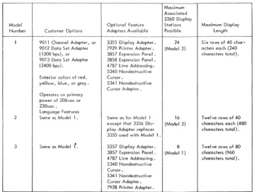
ruM 2848 Model Summary
Figure 1-1 summarizes the three 2848 models with· respect to the standard customer options, the applicable feature adapters, the models and num-ber of 2260 Display stations that can be serviced, and the maximum displayable message length. Special 2848 Features
Each of the customer-selection and special features that can be chosen to complement the three basic 2848 models is described in Figure 1-2. The in-formation provided on each feature consists of the feature code, the feature function, the 2848 models to which the feature can be attached, and any pre-requisite features. Language features are described separately in Appendix C.
The Isolation-Feature defined at the end of Figure 1-2 provides improved equipment performance by eliminating undesired logic signals that occur while power is removed from the unit. This feature enables the CE to perform maintenance tests on an "isolated" unit without affecting overall system operations. The feature is implemented by providing DSBL REQUEST/ INTF DSBLD switch (and indicator) on the 2848 op-erator's panel and a special selection Circuit modi-fication (explained in Chapter 2 under "Hold Select Circuits").
Operator Controls and Indicators
The 2848 controls and indicators available to the operator are limited to the control of unit power.
Maximum Associated
The controls (or indicator) and their functions are as follows:
1. Power On switch: provides ac power to dc power supplies.
2. Power Off switch: removes ac power from dc supplies.
3. Power On-Off indicator: lights when unit ac and dc power is on.
4. DSBL REQUEST/INTF DSBLD pushbutton/ indicator: permits a unit equipped with the Isolation Feature to be logically disconnected from the system.
5. REMOTE-LOCAL: in LOCAL, permits op-erator to control unit power; in REMOTE, transfers power control to system.
CE Panel
The 2848 Display Control is provided with aCE (maintenance) panel to permit local operation of the unit during checks and/or maintenance.
ruM 2260 DISPLAY STATION, GENERAL DESCRIPTION
The basic ruM 2260 Display Station contains the CRT display used to present data transferred from the associated System/360 and processed in the 2848 Display Control. There are two models of the ruM 2260 Display station: Modell, which is used with the Model 3 2848 Display Control only, and
2260 Display
Model Optional Feature Stations Maximum Display
Number Customer Opt ions Adapters Available Possible Length
1 9011 Channel Adapter, or 3355 Display Adopter. 24 Six rows of 40 char-9012 Data Set Adapter 7929 Pri nter Adapter. (Model 2) acters each (240 (1200 bps), or 3857 Expansion Panel. characters total). 9013 Data Set Adapter 3858 Expansion Panel.
(2400 bps). 4787 Line Addressing. 5340 Nondestructive Exterior colors of red, Cursor.
yellow, bl ue, or gray. 5341 Nondestructive Cursor Adopter. Operates on primary
power of 208voc or 230vac.
Language Features
2 Some as Modell. Same as for Model 1 16 Twelve rows of 40 except that 3356 Dis- (Model 2) characters each (480 play Adapter replaces characters total). 3355 used with Modell.
3 Same as Modell'. 3357 Di spl ay Adapter. 8 Twel ve rows of 80 3857 Expansion Panel. (Modell) characters (960 4787 Line Addressing. characters total). 5340 Nondestructive
Cursor.
5341 Nondestructive Cursor Adapter. 7928 Printer Adapter.
Figure 1-1. Summary of IBM 2848 Display Control Models
[image:13.613.61.427.429.700.2]3355 Display Adapter Contains storage and control logi c 1 only None for up to two 3355
to service two IBM 2260 Display adapters. A 3857 for up
Stations, Model 2. to six additional 3355
adapters. A 3858 for up to four additional 3355 adapters. A 3857 and a 3858 for maximum of 10 additional 3355 adapters.
3356 Display Adapter Contains storage and control logic 2 only None for one 3356
adap-to service two IBM 2260 Display ter. A 3857 for up to four
Stations, Model 2. additional 3356 adapters.
A 3858 for up to three additional 3356 adapters. A 3857 and a 3858 for the maximum of seven addi-tional 3356 adapters.
3357 Display Adapter Contains storage and control logi c 3 only None for one 3357. A
to service two IBM 2260 Display 3857 for up to three
addi-Stations, Modell. tional 3357 adapters.
9011 Channel Adapter Contains the circuitry required 1,2, None
(Selective Feature) to interface the 2848 with a and 3
System/360 selector or multi-plexor channel; operates in singl e-byte (8 bits) mode at a rate of up to 2560 characters per second.
9012 Data Set Adapter Interfaces the 2848 Display Control 1,2, Host System/360 must be
(Selective Feature) with a 1200-bps ( 120 characters and 3 equipped with an IBM
per second) communications data 4656 Term i nal Adapter,
set equivalent to the Western Type III (1200 bps).
Electric 202D Data Set. The data set interface meets the require-ments of the EIA 232A standard interface specification.
9013 Data Set Adapter Interfaces the 2848 Display Control 1, 2, Host System/360 must be
(Selective Feature) with a 2400-bps (240 characters and 3 equipped with an IBM
per second) commun i cations data set 4657 Terminal Adapter,
equivalent to the Western Electric Type II I (2400 bps).
201B Data Set. The data set inter-face meets the requirements of the EIA 232A standard interface speci-fication.
3857 Expansion Panel Permits the attachment of other 1,2, None
special features, as follows: and 3
For 2848 Modell: Six 3355 adapters.
For 2848 Model 2: Four 3356 adapters.
For 2848 Model 3: Three 3357 adapters.
Figure 1-2. IBM 2848 Display Control Features (Sheet 1 of 2)
Feature Code
3858 Expansion Panel
4787 Line Addressing
5340 Nondestructive Cursor
5341 Nondestructive Cursor .Adapter
7927 Printer Adopter
7928 Printer Adapter
IBM 4656 Terminal Adapter, Type III
IBM 4657 Terminal Adapter , Type III
Language Features
4700 Isolation Feature
Feature Description
Permits the attachment of other special features, as follows:
For 2848 Modell: Four 3355 adopters, one 7927 adapter. For 2848 Model 2: Three 3356 adapters, one 7927 adapter.
Permits the processor of the host ,ystem to select the first display-able position of any line within the CRT display of the 2260 Display Station as the starting location for the display of output data. The number of unique starting (or line) locations is:
2848 Modell: 6. 2848 Model 2: 12. 2848 Madel 3: 12.
Provides control logic for the
non-destructive cursor feature
repre-sented by the 5341 attached to the various display adapters. Allows the operator to move the cursor vertically and horizontally within the 2260 display.
Permits movement of the cursor within the CRT display of the 2260 without disturbing or destroying the dab displayed on the CRT.
Contains a buffer storage with a capacity of 960 characters and the logic required to control an IBM 1053 Printer.
Provides a means of obtaining a permanent printed record of dis-play group data under either
program or operator control.
Same as 7927.
Enables System/360 to communicate with the 2848 Display Control via a communications data set I ink formed by Western Electric 2020 Data Sets or their equivalent. Data transfer rate is 1200 bps (120 characters per second).
Same as 4656 except that the data set I ink must be formed by Western Electric 201B Data Sets or their equivalent. Data transfer rate is 2400 bps (240 characters per second).
See Appendix C.
Permits application and removal of power without affecting pro-gram operation.
2848 Model s to Wh ich Feature Can Be Attached
1 and 2
1, 2,
and 3
1, 2, and 3
Prerequisite 2848 Features
None
None
None
Note: If the 5340 Non-destructive Cursor feature is attached to a 2848 Display Control, all dis-play adapters used with the 2848 must be provided with the 5341 Nonde-structive Cursor Adapter.
Display Adapters: One 5340 per 2848. 3355 (Modell)
3356 (Model 2) 3357 (Model 3)
1 and 2 3858 Expansion Panel
3
Attaches to 2701 Data Adapter Units that include 2701 feature No. 3815 (one 4656 or 4657 can be attached) or 2701 feature No. 3855 (two 4656 or 4657 adapters can be attached) •
Same as 4656 •
1, 2, and 3
None
2848 Display Control at-tached to the same trans-mission I ine require the 9012 Data Set Adapter feature.
2848 Display Controls at-tached to the same
trans-mission I ine require the
9013 Data Set Adapter feature.
All Models using None the channel
adopter feature.
Figure 1-2. IBM 2848 Display Control Features (Sheet 2 of 2)
and related circuitry that matches the data capacity and character regeneration rate of the associated 2848 display control. Thus, a flicker-free display is assured whether the 2848 data capacity per diEi-play station is 960 characters (as in the Model 3 2848) or 240 or 480 characters (as in Models 1 and 2, respectively).
Optional features provide for the addition of an alphanumeric or numeric-only keyboard to the basic 2260 Display Station. This extends its capa-bilities to include man-to-machine communication, thus providing a complete visual I/O concept.
When an optional keyboard is included in the 2260 Display Station, input messages generated at the keyboard are displayed on the CRT as they are composed. This permits the operator to verify a message before it is transferred from the display group.
A total of 64 different characters can be dis-played on the 2260 Display Station CRT:
26 alphabetical characters 10 numerical characters
25 special symbols (includes space and new-line symbol)
3 control symbols (cursor, check, and start-manual-input symbols)
Special Features
Two special features, 4766 and 4767, are available to supplement the basic 2260 Display Station. Each feature provides the display station with an input keyboard as described below. The alphanumeric and numeric keyboards are also available with the key deSignations, special characters, and key-board arrangements required to complement the 2848 DC Language Features. (See Appendix C for a description of the language features.)
Feature 4766 Alphanumeric Keyboard
When optional feature 4766 is selected, the basic 2260 is fitted with the alphanumeric keyboard il-lustrated in Figure 1-3. The keyboard contains the 26 letters of the English alphabet, Arabic numerals 0-9, special symbol keys, and the control keys re-quired to format and enter the input message.
Feature 4767 Numeric Keyboard
Optional feature 4767 equips the 2260 Display Station with the numeric keyboard illustrated in Figure 1-4. The keyboard contains Arabic numerals 0-9 and the same set of control keys provided in the 4766 alphanumeric keyboard.
1-6 (4/67)
control keys are depressed is discussed in Chapter 6 for both the standard destructive cursor and the optional nondestructive cursor.
FUNCTIONAL DESCRIPTION
This operational description of the liM 2260 Display Station and liM 2848 Display Control display com-plex is at the block diagram level; it provides only enough detail to familiarize the reader with the broad concepts of equipment operation. A detailed discussion of display complex logic operation is provided in Chapter 2.
In the paragraphs that follow, the IBM 2260-liM 2848 display complex is first discussed at a level wherein the 2260 and 2848 are represented as blocks to show the functional make-up of the 2848 and to illustrate the relationship of the System/360 Chan-nel, the 2848, and the 2260. Next, an expanded block diagram illustrates the major logic areas within the 2848, and the function of each logic area shown is summarized. A similar block diagram analysis is provided for the IBM 2260. Finally, the data flow for a typical operation involving a maxi-mum of display complex logic areas is described.
liM 2848-2260 Display Complex
A typical IBM 2848-liM 2260 display complex is illustrated in Figure 1-5. Note that the 2848 is configured to include the channel adapter, the 1053 Printer Adapter, and two display adapters. Either the channel adapter or the data set adapter must be selected as part of the 2848. The channel adapter is shown in Figure 1-5. Similarly, at least one display adapter must be included in the 2848; two are shown in the figure to permit a more compre-hensive description of complex operation. The 1053 Printer Adapter has also been included although this adapter is optional. The liM 2260's shown all in-clude a manual input keyboard, which is optional.
All interchange between the System/360 channel and the 2848 is accomplished through the channel adapter. The channel adapter is capable of capturing common control under direction of the channel when the channel wishes to operate with a 2260 or with the 1053 Printer. The channel adapter also initiates communications with the System/360 under direc-tion of a 2260 Keyboard.
,
$ @l<
>
0/0 +*
( )1\
1
2
. 3 45
6 78
9 0 8KSP= #
,
PRINT ENTERI
Q
w
·
E. R T.y
U
0 P L ._ERASE NEW SURT
~ LINE
A~ S~ D::
F
'!
G
'·
H
~,l J -J<
:
L ' & DOWN UP:~ .~
·
~
c
!
l
i
v
~
;
B
.~'
~
N
~~
~~' ' /' ~.? SHIFT
~~I ! , X"
,.
" ;,'.
,I II" \ ii.~ SHIFTSPACE I ERASE - J. ADYANCE
Figure 1-3. Optional Alphanumeric Keyboard for 2260 OS
Figure 1-4. Optional Numeric Keyboard for 2260 OS
IBM 2848
Display Control Channel
T
J 053 Printer AdopterI
AdapterCommon Control
Disploy
I
Adopter
Display Adapter
I
Sync and Video
l
t
Kybd Inputs
I
I
t
Kybd InputsSync and Video
IBM 2260
Display Station
Kybd
, -Sync
ond Video [Kybd
II~puts
IBM 2260
Display Station
Kybd
~puts
Sync and
l
deo IBM 2260Display Station
Kybd
IBM 2260
Display Station
Kybd
Figure 1-5. IBM 2848 - IBM 2260 Display Complex, Block Diagram
commands from the channel (via the channel adapter) and from the keyboards. Common control also generates the sync used to control all displays as-sociated with the display control. The display stations are controlled in two groups, even displays and odd displays. In Figure 1-5, note that each display adapter services two display stations, one an even display and the other an odd. The even and odd designations normally agree with the device ad-dress assignment of the display station; i. e., Dis-play Station 03 is odd, 04 is even, 05 is odd, etc.
Common control first services all even displays as a group. This servicing includes only the alternate gating of video, first to one group and then to the other. Sync is supplied continuously to all display stations to maintain the desired sweeps (position-ing) within the display. The even-odd concept is used throughout display control operations as a means of selecting and updating on a particular display.
The display adapter contains the delay lines and controls required to service two 2260 Display Sta-tions. The controls portion includes the logic cir-cuits required to write and read data in the delay lines and parts of the keyboard selection and gating logic.
The IBM 2260 Display Station receives a com-posite sync and video signal from the display control. This signal both controls the sweeps (displa.y) on the CRT of the 2260 and transfers video that is t~ be
1-8 (4/67)
seven-bit bytes transferred as a result of a key de-pression at the keyboard. The seven-bit bytes con-tain either keyboard commands or data.
The 1053 Printer adapter contains the storage and controls required to permit control of a 1053 Printer by the channel or to print a hard copy of the contents of any display station's display.
IBM 2848 Display Control
The IBM 2848 is shown in block diagram form in Figure 1-6, with each major logical element repre-sented as a block. The function of each block is discussed. Note that the 2848, as illustrated, in-cludes the channel adapter, the 1053 Printer adapt-er, and two display adapters. The 2848 control and timing circuits are illustrated in Figure 1-7 and are discussed separately.
Channel Adapter
• Provides the required interface between System/360 channel and the IBM 2848 Dis-play Control.
• All communication with the channel is ac-complished through the channel adapter. When the 2848 Display Control is to operate in a local configuration with a System/360, the channel adapter is included to provide the required interface between the System/360 channel and the display con-trol. The channel adapter then forms the connecting link through which all data and control exchanges between the channel and display control are made. The interface established is essentially the same as the standard IBM System/360 Interface Channel to Control Unit, which is used for interfacing other I/O equipments to the system.
The major logic elements of the channel adapter are illustrated in block diagram form in Figure 1-6. The functions of the logic areas are as follows:
1. Bus Out: The channel adapter receives com-mands, addresses, and data from the system channel via Bus Out, which consists of nine lines (bit positions 0-7 and a parity bit). 2. Character Register: This eight-position latch
register can be loaded from Bus Out (8 bits) or from the common buffer register of common control (6 bits). The character register also converts the eight-bit code received from the channel to the six-bit code used within the 2848 and performs a reverse conversion when in-formation is transferred from the 2848 to the channel; i. e., six-bit to eight-bit conversion. 3. Command Decoder and Register: Decodes
Pulse Circuit
Bit Ring Counter (7 Bits)
L - - Row Counter
----+
(3 Bits)Character Display
~ Column Ring
..
(6 Bits)
Figure 1-7. Timing and Clock Circuits, Simplified Block Diagram
sets command register latch associated with the command.
4. Bus Out Parity Check: Checks for odd parity of each byte sent to channel adapter via Bus Out.
5. Address Check: Detects unit address on Bus Out and enables address register and encoder circuits when unit address is decoded.
6. Address Register: Converts eight-bit address byte from channel into five-bit device address; sets address into address register for trans-fer to address decoder of 2848 common con-trol.
7. Address Compare: Compares the address on Bus Out with contents of address register if a busy condition exists when the address is issued; if the addresses compare, a Device Busy latch is set, and a special sequence is entered. If an address compare is not made, the channel is presented with Control Unit Busy in the status byte.
8. Status Register: Records unit status for trans-fer to channel via Bus In.
9. Sense Register: Records information that amplifies unit status conditions indicated by the contents of the status register 0
10. Parity Assign: Assigns odd parity to all eight-bit bytes transferred to the channel via Bus In. 11. Bus In: A nine-line path (bits 0-7 and a parity
bit) over which all data transfers from the channel adapter to the System/360 channel are accomplished.
U
B Delay
Even Display Even
Odd Display
Odd Display Trigger
I
Segment Counter (3 Bits)
I
LI
RI I
VerticalHigh Speed Sync
Gener-Horizontal ator
Line Counter
-(9 Bits) Low Speed
IBM 2848 Common
• Command and data inputs are received as six-bit bytes via the character register of the optional channel adapter.
• Address information is received as a five-bit byte from the channel adapter addre ss register.
• Data and control information is transferred to the channel via the character register of the channel adapter.
• The address register of the channel adapter can be set with a five-bit address originating from the display control address register to identify the originating keyboard during Enter commands.
• Display common provides a seven-bit tilt-rotate code as an output to the 1053 Printer adapter.
• Accommodates up to 24 2260 Display Sta-tions (2848 Modell) and one 1053 Printer adapter.
·
·
·
·
..
The display common contains the control circuitry that is shared by the interface, printer adapter, and display stations (keyboards) to effect the various display operations. The major logical elements of display control are illustrated in block diagram form in Figure 1-6. Note that all communication with the System/360 channel is accomplished through the character register and address registers of the optional channel adapter. System/360, using the channel adapter as the connecting link, can configure
[image:20.618.65.583.58.307.2]the common display control circuits to permit chan-nel operation with any 2260 Display Station associated with the display control or with the 1053 Printer (via the optional 1053 Printer adapter).
The display common circuits can also be
con-trolled by any associated display station provided with a keyboard. Then, display control permits data entry into, or modification of, the display data stored in the display station adapter. Display control also causes input messages to be sent to the System/360 channel via the channel adapter when this action is initiated at a display station keyboard (Enter com-mand).
The functions of the major logic areas of display control are as follows:
1. Common Buffer: This seven-bit latch register serves as the hub for all data and control word transfers.
2. Data Decode: Senses contents of common buf-fer register for SOM, NL, and EOM codes except during Read Buffer commands. 3. Set EOM: Provides a means of setting the
six-bit EOM code in the common buffer reg-ister when required by the operation being performed.
4. Character Generator and Code Translator: Converts the six-bit character code set in the common buffer register from either the chan-nel (via chanchan-nel adapter) or the keyboards into five 7 -bit bytes, which are stored in the delay lines and used to generate video for character display; also performs code translations, e. g. , six-bit character code to 1053 tilt-rotate code. 5. Serializer: Converts the contents of the common
buffer register into serial data that can be writ-ten in the delay lines of the selected adapter. 6. Parity Assign: Assigns even parity to groups
of data (slots) stored in the delay lines. 7. Parity Check: Checks for even parity as BCD
data is read from the delay lines of the selected adapter for ultimate transfer to another location. 8. Address Encoder: Encodes a five-bit address
used to select a display and to identify the active keyboard.
9. Address Register: This five-bit latch regis-ter is set from either the address encoder
(keyboard operation) of the address register or the channel adapter (channel operation); also used to set address of originating key-board in the channel adapter address register during keyboard Enter commands.
10. Address Decoder: Decodes the five-bit ad-dress to select a particular display station or the 1053 Printer.
11. Keyboard Priority: Determines which key-board is to be serviced when more than one keyboard requests control of display control common.
1-12 (4/67)
12. Keyboard Gating: Accepts inputs from all associated keyboards on common bus; how-ever, only the selected keyboard's outputs are gated through to keyboard command
... "'"... ... .: ... +. ... ,.. .LvO~i:)LCJ. •
13. Keyboard Command: Decodes keyboard com-mand bytes and sets the comcom-mand latch as-sociated with the command.
The functions of the logic areas within the adapt-ers illustrated in Figure 1-6 are as follows:
1. Delay Lines: Provide a storage medium for display data; provide video outputs to associ-ated display station; provide six-bit BCD character codes during read operations. 2. Read Control: Controls the extraction of
data from the delay lines.
3. Write Control: Controls the entry of data into the delay lines.
1053 Printer Adapter
• Permits the use of a 1053 Printer as a sys-tem output device under control of the channel.
• Provides hard copy of any 2260 Display Station's display upon direction either by the channel or from the display station key-board (Print commands).
The functions of the 1053 Printer adapter logic elements, as illustrated in Figure 1-6, are as fol-lows:
1. Print In Buffers 1 and 2: Used to buffer character inputs from display control to the printer adapter. The two buffers enable the printer adapter to accept inputs at a speed adequate for operation under control of the System/360 channel.
When the character is in Print In Buffer 2, a check is made to determine whether a case-change (upper case to lower case, or lower case to upper case) is necessary. If a case-change must be made, a case-case-change charac-ter is inserted in the delay line before the character code is stored.
2. Parity Assign: Assigns odd parity to all characters written in the delay line; parity is stored with the character.
3. Delay Line: Provides a storage medium that permits proper message assembly and sub-sequent readout to the printout buffer. 4. Write-Read Control: Controls the storage
of data in the delay lines (write) and subse-quent extraction (read) of the data.
7. Character Decode: Detects the presence of nonfunction codes in the printout buffer and causes transfer of the code to the printer magnets.
8. Function Decode: Detects the presence of printer function codes in the printout buffer and causes the desired function to be per-formed.
9. Printer Controls: Controls the loading of print-in and printout buffers and the insertion of special characters (shift, carrier return, etc.) where required; includes a nine-bit ring counter which provides basic timing for printer adapter operations.
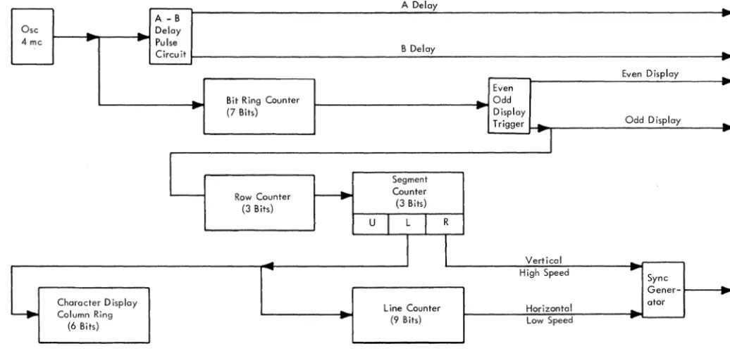
Control and Timing
The illustration of the common control area of the IBM 2848 in Figure 1-6 does not include the deriva-tion of basic machine timing, which affects all areas and is significant enough to warrant separate illus-tration and discussion. Figure 1-7 illustrates the timing scheme. Figure 1-8 shows the odd and even displays and illustrates much of the timing discussed in the paragraphs that follow. The functions of the timing blocks in the figure are as follows:
1. Oscillator: Provides basic timing pulses at a frequency of 4.0 mc.
2. A-B Delay Circuits: Provide 2.0-mc A Delay and B Delay timing pulses 180 degrees out of phase.
3. Bit Ring Counter: This seven-bit ring counter is stepped at a rate of 4 mc; it is stepped al-ternately from 1 to 7 during even display outs and from 1 to 7 during odd display read-outs. The seven outputs of the bit ring counter are used throughout the machine as timing pulses and are used in bursts of 7 to write and read the delay lines of the display adapters. 4. Even-Odd Display Trigger: This trigger is
complemented each time the bit ring counter reaches a count of 7. The outputs of the trigger are used to establish time intervals for operating with either the even or the odd display serviced by a display adapter.
5. Row Counter: Essentially, this counter keeps track of the horizontal rows of characters dis-played on the CRT. Note that the row counter is stepped each time that the Even-Odd trigger is at Odd. This represents the indexing of (for example) row 1 on the even display, row 1 on the odd, and next (since the row counter is stepped upon odd display), row 2 of of the even display, row 2 of the odd, etc.
the vertical sweep: "upper" refers to the upper half of the display area, "lower" re-fers to the lower half of the display, and "retrace" refers to vertical retrace time during which the CRT beam must move from the bottom of the display area to the top. The segment counter is stepped each time the row counter has counted all the rows in a segment. (There are six rows in upper and six in lower, and the row counter continues to count during retrace time.)
7. Character Display Column Ring Counter: As shown in Figure 1-8, each character is com-posed of six lines within the display. These lines are deSignated as BCD, VI, V2, V3, V4, and V5. The character display column ring counter keeps track of which type of line (BCD or VI (video 1), V2, V3, V4, or V5) is being displayed. The counter is stepped at the end of lower segment time since this rep-resents the point at which the sweep of one particular line is ended.
8. Line Counter: This nine-bit line counter keeps track of a horizontal position within the dis-play by counting vertical lines (or sweeps). The line counter is stepped at the end of lower segment time, which represents the end of a vertical sweep.
IBM 2260 Display Station
The IBM 2260 Display station is illustrated in block diagram form in Figure 1-9. Note that its only interconnection with the 2848 Display Control is a composite signal which contains both video and the sync signals necessary to generate the vertical and horizontal sweeps for the CRT plus a character spacing signal. The composite signal is amplified and applied to the cathode of the CRT to effect the video presentation. Sync signals within the composite signal are extracted through the integrator and dif-ferentiator circuits shown as blocks in Figure 1-9. The horizontal and vertical deflection voltages (sweeps) are then developed and applied to the de-flection coils of the CRT. The vertical sweep is very fast in relation to the horizontal sweep because, as can be seen in, Figure 1-8, many vertical excursions of the beam are required for each horizontal pass across the tube.
The 12-kv high-voltage supply provides the high dc anode voltage required for CRT operation.
2260/2848 - 60,000S FETOM (4/67) 1-13
SYSTEM/360 - CHANNEL ADAPTER INTERFACE
• The I/O interface signal lines connect the channel adapter of the IDM 2848 Display Control to other control units and to the System/360 channel.
• The lines are functionally divided into five groups:
1. Bus Out 2. Bus In 3. Tags
4. Selection Controls 5. Metering Controls
• All transfers of data and control information between the 2848 and the System/360 pro-cessor channel are made through these lines.
Understanding basic interface operation is essential to understanding the 2848 and, particularly, this section of the manual. This information is avail-able in the Original Equipment Manual (OEM), IDM System/360 Channel Interface, Form A22-6843. Although an understanding of the basic interface is assumed, this information is reviewed in the fol-lowing paragraph.
General
The I/O interface is a set of signal lines connecting an I/O control unit to the host System/360. The ex-ternal cables physically connect all control units in a chain, with the first control unit being connected to a System/360 channel.
The signal lines of the I/O interface consist of an output and an input bus for passing information from channel to control units, tag lines for inter-locking and for controlling the information on the buses, selection control lines for scanning or selecting the
II
0 device, and metering controls for conditioning the usage meters.The following signal lines are used (the terms Out and In are in reference to the channel):
Line Name Abbreviation
Bus Out Position P Bus Out P
Bus Out Position 0 Bus Out 0
Bus Out Position 1 Bus Out 1
Bus Out Position 2 Bus Out 2 Bus Out
Bus Out Position 3 Bus Out 3
Bus Out Position 4 Bus Out 4
Bus Out Position 5 Bus Out 5
Bus Out Po