2016 International Conference on Electronic Information Technology and Intellectualization (ICEITI 2016) ISBN: 978-1-60595-364-9
Based on the FPGA Video Image Enhancement
System Implementation
Hui Li, Fei Xiang and Ligong Sun
ABSTRACT:
According to the changing external environment, or night fog cases collected a blurry image. In this paper, the conventional histogram equalization algorithm is optimized and improved, as well as an adaptive histogram equalization algorithm is proposed, which can effectively control the contrast ratio. To convert images from the RGB space to HSI space, and then to HSI space of luminance component (I) of gray histogram for optimization of the algorithm, and then convert to RGB space. The realization of the algorithm by FPGA, image recognition degree enhanced obviously, improve the quality of the image, the actual application effect is superior.
INTRODUCTION
With the acceleration of industrialization process, the environment is rapidly deteriorating, severe haze weather, under the environment of high resolution is not collected image resolution is not very ideal. So the study of color image enhancement technology is particularly important. Because of the color image R, G, B components are related to each other, if the color image enhancement directly, easy to result in enhanced image color distortion[1]. Convert RGB to HSI space can better reflect the visual characteristics, and then in HSI space for the processing of image enhancement algorithm, after processing the image contrast and image quality was increased obviously[2].
_________________________
On the hardware, the FPGA is parallel processing in the structure, so it can carry out high speed operation, and FPGA system structural is strong, flexibility. Considering the above factors, the system adopts the CycloneIV series EP4CE10E22C8N FPGA as the processor, convert RGB space to HSI space, realize the image enhancement in HSI space, and then converted into RGB color space to HSI space. This scheme is relatively simple, high integration, low power consumption advantages.
IMAGE ENHANCEMENT ALGORITHM
A. Algorithm Principle
RGB (red, green, blue) color space is one of the most widely used color space. Through the change of the red, green, blue three primary colors and overlay each other between them for a variety of different colors. HSI (hue, saturation, intensity) of H for color wavelength is called tonal, S for color depth degree is called saturation, I for intensity or brightness, corresponding to the image brightness and image grayscale[3]. People feel the color way is closely related to the H and S components and the I component has nothing to do with the image color information. They can be handled separately and are independent of each other, so it is suitable for image analysis and processing[4].
The ideas of the algorithm is to convert the image from the RGB space to HSI space, secondly the I component of the gray histogram of HSI space effectively control contrast adaptive histogram equalization processing, to improve the brightness of the image and then back to the RGB space to display.
A. Color Image is Firstly Transformed From RGB Space to HSI Space.
The basic idea of the transformation process is to separate the luminance component first and transform the three-dimensional space into a two-dimensional one, then with the help of the vector dot product formula of analytic geometry, the hue value of the HSI model in the two-dimensional plane can be further derived.
The specific process is as follows: 1) Normalize the values of RGB.
R r
R G B
,
G g
R G B
,
B b
R G B
(1)
1
1
2 2
0.5 [( ) ( )]
cos
[( ) ( )( )]
r g r b h
r g r b g b
0,h forbg (2)
1
1
2 2
0 .5 [( ) ( )]
co s
[( ) ( )( )]
r g r b h
r g r b g b
1 3 min( , , )
s r g b (3)
[0,1]
s ,i(R G B) / (3 255) ,i[0,1]
3)Transform the values of H, S and I into the ranges of [0,360], [0,100] and [0,255], respectively.
180 /
H h ; S s 100 ; I i 255 (4)
B. Use Optimal Histogram Equalization Algorithm to Process The I Component.
Histogram Equalization algorithm is one kind of image processing method that adopts the image histogram to adjust image contrast[5]. However, the appearance of image detail information loss always occurs brought by conventional histogram equalization algorithm processing course, which makes the effect is not as good as expected. In this paper, the conventional histogram equalization algorithm is optimized and improved, as well as an adaptive histogram equalization algorithm is proposed, which can effectively control the contrast ratio. According to the maximum gray level probability density of the histogram and the average brightness of the image, the proposed algorithm can realize the self-adaptive adjustment of the histogram. With the processing course of the proposed algorithm, the dynamic scope of the pixel gray scale is expanded, as well as the image contrast is significantly enhanced.
The specific algorithm processing steps are as follows:
1) Get the probability density ( )P k (k=0,1,…,L-1) for all gray levels of the original image, where L is the total number of the gray levels;
2) Calculate the maximum probability density Pk and define P0 Pk /2;
Calculate the average luminance value Im:
Calculate the newly generated histogram P t
k :
k h
k ( ) ( )( 0 ( ))P t P k k P P k whenP k( )P0; (7)
among: ( ) (1 m )2 (1 )
m
I k
k
I
when 0andkIm; (8)
2
( ) (1 ) (1 ) ( 1)
m
m
k I
k
L I
when 0andkIm; (9)
( ) 0k
when 0; (10)
、 are regulation parameter.
Transform pixel gray-value D into gray value ( , )f x y :
0
( ) ( 1) D ( )j
j
f D L P t
(11)C. After The Recombination of I,H And S Components, And Then Transform Each of Them Into RGB Space.
The transformation of HSI space into RGB space is the inverse process of the calculation course of transforming RGB into HSI, as is shown below.
/180;
hH sS/100; iI/ 255
(1 )
x i s , [1 cos( ) ]
cos( / 3 )
s h
y i
h
,z 3i (x y); (12)
whenh2 / 3 , bx,r y,g z;
when 2 / 3 h 4 / 3, h h 2 / 3, rx,g y,bz.
The R, G, B parameters are normalized values obtained by using the equations above, whose ranges are between 0 and 1, and these three values need to be multiplied by 255 to get the final RGB values.
HARDWARE IMPLEMENTATION
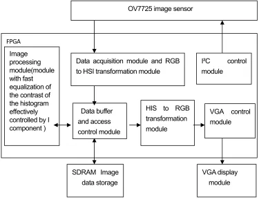
OV7725 digital image sensor is introduced in the system for image acquisition, in addition, the image processing module and the rest of peripherals are combined with a Cyclone IV series FPGA microchip, whose model is EP4CE10E22C8N with 10000LE on-chip resource. A Hynix HY57V641620 RAM chip is chosen as the SDRAM of the system, which has 4M*16bit capacity available. The overall structure of the proposed system is presented in Figure.1.
A 50MHz crystal oscillator is adopted to provide the input clock for the FPGA based system. OV7725 image sensor is controlled by the FPGA through I²C interface where the I²C bus transmitting information is simulated by the control logic inside the FPGA, hence the control register, working mode and the output RGB image format of the image sensor can be preset in this way. After the accomplishment of system parameter initialization , the integrated PLL circuit would provide a 24MHz clock for the image sensor, and the RGB data then can be read from the sensor synchronized with the control signal as the VSYNC and HREF data must be valid here.
CMOS_PCLK signal is taken as the system master clock. Simply by capturing CMOS-VSYNC and CMOS-HREF signals, the data acquisition course can be achieved with the data expressions of 1280 in each row and 640 rows in each frame.
The data transmitted through the OV7725 image sensor is then transferred to the format conversion module, in which unit the conversion of the format is done for the transformation of RGB space into HSI space. After transformation process finished, it only needs to collect the I component information for the transformed image. Subsequently the collected values of I are taken as the RAM addresses, then by storing the each pixel with diverse brightness into different addresses to complete the histogram statistics, and the proposed algorithm is adopted for coping with the image according to the statistical results of the histogram.
In this design, due to OV7725 image sensor working in 24MHz, as well as the CMOS_PCLK signal is 24MHz, the control clock of SDRAM is 100MHz, the driving clock signal of SDRAM is 100MHz after the phase-offset, and the VGA scan clock is 25MHz with a resolution of 640*480@60Hz. Therefore, the integrated PLL is used for the managements of the global clock..
module. The processed image data will be stored in SDRAM subsequently. At last the ping-pong operation is adopted to cope with the data, and by
Figure 1. Overall structure of the proposed system.
means of the row caching process of the FIFO, the processed image data in the SDRAM memory is then transferred into the HSI-RGB transformation module. Finally, the HSI space of the image is transformed into RGB space, and with the help of VGA control module, the enhanced color image is displayed on the VGA display. The architecture of I²C protocol is one kind of serial communication bus. By means of this interface, the resolution, internal clock, brightness, chromatic aberration and 3A parameters of an applied system can be preset. I²C bus only occupies two signal interfaces, i.e., the serial data line SDA and the serial clock line SCL. In this system, the slave unit, OV7725 image sensor, is controlled by the primary FPGA controller .
EXPERIMENTAL RESULTS AND ANALYSIS
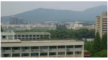
The FPGA based testing board is designed for the propose of image processing, as is shown Fig.2. And the processing course has been implemented on a specific image with the help of the proposed algorithm, and the comparison results of the pre-processing and post-processing of the image are shown as follows.
FPGA
OV7725 image sensor
SDRAM Image data storage
VGA display module Image
processing module(module with fast equalization of the contrast of the histogram effectively controlled by I component )
Data acquisition module and RGB to HSI transformation module
Data buffer and access control module
I²C control
module
VGA control module HIS to RGB
Figure 2. The proposed image processing platform. Figure 3. Original image.
[image:7.612.306.479.95.191.2]
Figure 4. The result of conventional histogram Figure 5. Image processed by the equalization processing. proposed Algorithm.
TABLE I. A performance comparison for the conventional and the proposed algorithms.
Fig.3 shows the image status before processing, and Fig.4 presents the comparison results of the pre-processing and post-processing of the image, and the same comparison course has been made on the by using the proposed algorithm, as is shown in Fig.5. It can be seen that the original image tends to be gray, and the image effect has been greatly improved after applying the conventional histogram equalization algorithm, and the contrast effect is not as obvious as expected yet, whose overall look still appears to be a little dark, and it is also can be seen that, after the processing course of the proposed algorithm in this paper, the clarity and visual effects of the image have been improved significantly, as well as the image details tends to be more rich, and the experimental effects are evident. In the external environment is not very good, Enhancement algorithm Average gradient value of the gray level Real time performance/ms
Conventional algorithm 8.516 3.362
[image:7.612.99.288.244.344.2] [image:7.612.90.494.424.503.2]increase the sharpness of the image well, in the case of low resolution is applied in video monitoring, etc. Has extensive practical applications.
CONCLUSIONS
FPGA has the function of the flexible parallel, real-time processing image data, very suitable for a large amount of data, transmission speed of the color image enhancement processing, so choose FPGA as the core of the whole algorithm processor. Through the synergy to complete each image processing module and mutual transformation between RGB space and HSI space gray image acquisition and real-time enhancement algorithm, and use the software to realize the histogram statistics and histogram equalization algorithm in parallel. System by using Verilog hardware programming language to write each functional module. Table I shows using this algorithm is faster than traditional algorithm 0.83 ms, the experimental results show that this system has high integration, good real-time algorithm, has a good practicability.
REFERENCES
1. Yin Chuan-li, Wang Xiao-zhe. Design and Realization of Airborne Embedded Image Enhancement System [J]. Chinese Journal of Liquid Crystals and Display, 2013(4); 604-607.
2. Zhao Jian, Zhao Fan, Qu Feng. Implement of system for color image enhancement in real-time based on FPGA [J]. Chinese Journal of Liquid Crystals and Display, 2014(4); 629-636.
3. Yang Fan, Zhang Hao. Image processing system based on FPGA [J]. J. Huazhong Univ. of Sci, 2015, 43(2): 119-123.
4. Kwiatkowski, Jan; Daniec, Krzysztof; Jdrasiak, Karol; Sobel, Dawid; Real time Thermogram enhancement by FPGA-based contrast stretching [J]. Intelligent Information and Database Systems - 8th Asian Conference, ACIIDS 2016, 487-496.