2017 3rd International Conference on Computer Science and Mechanical Automation (CSMA 2017) ISBN: 978-1-60595-506-3
The Direct Quaternion Method in Initial Alignment of SINS
Shi-Jiao AN
1,2,*and Chun-Xi ZHANG
11
School of Instrumentation Science and Optoelectronics Engineering, Beihang University, Beijing, China
2
Beijing Institute of Electronic System Engineering, Beijing, China E-mail: [email protected]
Keywords: Quaternion, Initial alignment, SINS, Mathematical simulation.
Abstract. In this paper, the initial quasi-quaternion method of strapdown inertial navigation system (SINS) is proposed, in order to solve the singularity problem of the initial alignment algorithm. And mathematical simulations is conducted and analysed Simulation results show that the method is feasible.
Introduction
The purpose of the initial alignment of the strap down inertial navigation system (SINS) is to establish the initial value of the strap down matrix. The initial alignment error is one of the main error sources of the SINS, which directly affects the precision of the inertial navigation system (INS). At present, there are three main methods for calculating the attitude angle of the SINS, that is the direction cosine method, the Euler angle method and the quaternion method. The directional cosine method, which solves the direction of the cosine differential equation, needs to solve the nine significant computational differential equations. It is not practical in engineering. The Euler angle method can be directly to the three attitude angle. But it depends on the rotation order, and it cannot work in all pose. Having advantages of relatively small amount of calculation, the quaternion method has been widely used in engineering. At present, the method commonly used in engineering is based on the initial alignment method of the quintuple of Euler angles. The method needs to find the Euler angle first, and then calculation of the initial quaternion. There is a singularity in solving the Euler angles. In this paper, an initial alignment method is investigated to solve this problem. This method avoids solving the Euler angles and can obtain the quaternion directly through the quaternion attitude transformation matrix.
Initial Alignment method for SINS
For a SINS, the key to the initial alignment lies in the precise pursuit of the high-precision strap down attitude matrix. The attitude matrix in the strap down inertial navigation system is equivalent to making a coordinate transformation on the platform system. This mapping plays a platform role. Therefore, the attitude matrix can also be regarded as a "mathematical platform". Attitude matrix is the function of the attitude angles named
ψ
,ϑ,γ
, which are formed in accordance with a certain Euler angle sequence on the rotation of the coordinate system.The transformation from the navigation coordinate systemO X Y Zn n n n to the projectile coordinate
systemO X Y Zb b b b is achieved by successive rotation (without considering the movement of the origin
of the coordinate): the First, rotate around the axisO Yn n by the angle
ψ
.Then rotate around the newaxisO Zn 'nby the angleϑ,and then around new axis O Xn "n (ie, the axisO Xb b) by the angle
γ
.ψ
,ϑ,γ
cos cos
sin
cos sin
sin cos cos
sin sin
cos cos
sin sin cos
cos sin
sin cos sin
sin cos
cos sin
cos cos
sin sin sin
b n
C
ψϑ γ
ϑ
ψ
ϑ
ϑ
ψ
ϑ
ψ
γ
ψ
γ
ϑ
γ
ϑ
ψ
γ
ψ
γ
ϑ
ψ
γ
ψ
γ
ϑ
γ
ψ
γ
ϑ
ψ
γ
−
= −
+
+
+
−
−
(1)With the elements of the above matrix we can determine the main value of the attitude angleϑ,
ψ
,γ
. The commonly used acquisition methods of the attitude matrix are numerous including used direction cosine method, Euler angle method, quaternion method and rotation vector method, etc. In order to reduce the computational complexity and avoid the singularity. In this paper, a direct quaternion method is proposed to calculate the attitude matrix.
Quaternion Initial Alignment Method
Coordinate System Definition
The coordinate system involved in this paper is as follows:
a)the navigation coordinate system(O X Y Zn n n n)
OriginΟn: located in the launch frame positioning point;
AxisΟnXn: with the point through the tangent line of heavy, pointing to the north is positive;
AxisΟnZn: with the point through the weft tangent, point to the east is positive;
AxisΟnYn: along the origin of the vertical line, pointing to the positive;
After the launch with the earth, with the earth together.
b)the missile coordinate system(O X Y Zb b b b)
OriginOb: located in the missile center of mass;
AxisO Xb b: along the longitudinal axis of the missile, pointing to the missile head is positive;
AxisO Yb b: in the longitudinal plane of the missile, perpendicular to the axisO Xb b, pointing to the
positive;
AxisO Zb b: according to the right hand rule to determine.
Relationship between Quaternion and Attitude Angle
The quaternion, which represents the attitude matrix from the navigation coordinate system to the missile coordinate system is:
2 2 2 2
0 1 2 3 1 2 0 3 1 3 0 2
2 2 2 2
1 2 0 3 0 1 2 3 0 1 2 3 2 2 2 2 1 3 0 2 2 3 0 1 0 1 2 3
2( ) 2( )
2( ) 2( )
2( ) 2( )
+ − − + −
= − − + − +
+ − − − +
b n
q q q q q q q q q q q q
C q q q q q q q q q q q q
q q q q q q q q q q q q
(2)
The attitude angle is defined as the order of the first yaw and then the last roll. The attitude matrix from the navigation coordinate system to the missile coordinate system is:
1 0 0 cosϑ sinϑ 0 cosψ 0 −sinψ
Initial Alignment Method Using the Quaternion
In the initial attitude, the initial alignment equation is:
0 1 0 x y b n z f g f C g f g = (4) Then (5) According to the relationship between the quaternion and the attitude angle, the equation is:
(6) The equation of direct quaternion method is:
2 2 2 2
2 2
2 2 2 2
2 2 2 2
2 2
2 2 2 2
2 2 2
2
2 2
1 1
0 (1 1 ( ) ) cos (1 1 ( ) ) sin
2 2 2 2
1 1
1 (1 1 ( ) ) cos (1 1 ( ) ) sin
2 2 2 2
1 1
2 (1 1 ( ) ) cos
2 2 2
y z y y y z y y
y z y z
y z y y y z y y
y z y z
y z y y y z
y z
f f f f f f f f
q
g g
f f f f
f f f f f f f f
q
g g
f f f f
f f f f f f
q g f f ψ ψ ψ ψ ψ + + + − = + − − − − + + + − + + = + − + − − + + + − + = − − + + 2 2 2 2
2 2 2 2
2 2
2 2 2 2
(1 1 ( ) ) sin 2
1 1
3 (1 1 ( ) ) cos (1 1 ( ) ) sin
2 2 2 2
y y
y z
y z y y y z y y
y z y z
f f
g
f f
f f f f f f f f
q
g g
f f f f
ψ ψ ψ + + − + + + + − = − − − + − + + (7)
where
ψ
is obtained by binding.Mathematical Simulation
[image:3.612.104.486.285.454.2]The specific conditions and simulation results of the initial alignment simulation condition are shown in Table 1. Simulation of the relevant curve shown in Figure 1 to Figure 4.
Table 1. Specific conditions and simulation results.
Attitude angle character paragraph
Simulation conditions
set0 -0.6 -0.646
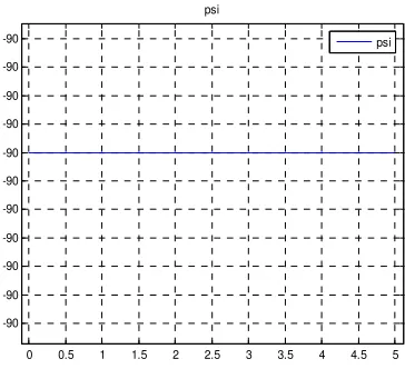
psi0 -90 -90
Figure 1. Initial alignment pitch curve. Figure 2. Initial alignment yaw curve.
Figure 3. Initial alignment of the roll angle curve.
1 1.5 2 2.5 3 3.5 4 4.5 5 -0.6467
-0.6467 -0.6466 -0.6466 -0.6465
set
set
0 0.5 1 1.5 2 2.5 3 3.5 4 4.5 5 -90
-90 -90 -90 -90 -90 -90 -90 -90 -90 -90
psi
psi
1 1.5 2 2.5 3 3.5 4 4.5 5 -0.2996
-0.2995 -0.2995 -0.2994 -0.2994
gam
gam
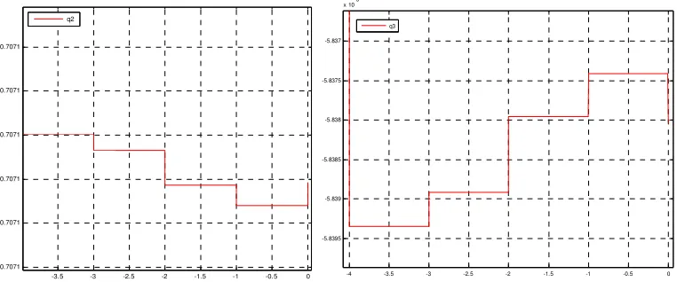
0.7071 0.7071 0.7071 0.7071 0.7071 0.7071 0.7071 0.7071
0.7071 q0
2.1418 2.1419 2.142 2.1421 2.1422 2.1423 2.1424 2.1425 2.1426
Figure 4. Initial alignment quaternion curve.
Conclusion
Aiming at solving problems of pose angle singularity in the initial alignment of SINS, a quaternion alignment method is proposed. The calculation amount of quaternion method is small and there is no singularity. The initial alignment method of quaternion is obtained directly by quaternion attitude transformation matrix, which can improve both the efficiency of initial alignment and apply larger attitude angle range.
References
[1]Qin Y. Inertial Navigation [M]. Science Press, 2010: 203-355.
[2]Su Z, Li Q, Li K, etc. Inertial technology [M]. National Defence Industry Press. 2010: 92-168.
[3]Wan D, Fang J. Inertial navigation initial alignment [M]. Southeast University Press. 1998: 1-82.
[4] Wu T, Ma L, Li Z. Application of strapdown inertial navigation system analysis [M]. Defence
Industry Press. 2011: 117-258.
[5]Zou Z, Du Z. Study on Initial Alignment of Platform Inertial Navigation System and Its
Debugging [J]. Journal of Chinese Inertial Technology, 1995, 3 (3): 25-31.
[6] Fang J, Wan D. Study on Fast Alignment Method of Strapdown Inertial Navigation System [J].
Journal of Southeast University, 1996, 26 (2).
[7]Chen L, Liu J, Sun Y, etc. Study on Analytical Alignment Method for Micro Strap-down Inertial
Navigation System [J]. Space Control, 2005, 23 (4): 9-23.
[8] Ren L. Initial alignment method of strap-down inertial navigation system [D]. Harbin: Harbin Engineering University Master's thesis, 2010: 1-7.
[9]Yang Y, Tan J, Deng Z. Overview of Initial Alignment of Inertial Navigation System [J]. Journal
of Chinese Inertial Technology, 2002, 10 (2): 68-72.
-3.5 -3 -2.5 -2 -1.5 -1 -0.5 0
-0.7071 -0.7071 -0.7071 -0.7071 -0.7071 -0.7071
q2
-4 -3.5 -3 -2.5 -2 -1.5 -1 -0.5 0
-5.8395 -5.839 -5.8385 -5.838 -5.8375 -5.837