2017 3rd International Conference on Electronic Information Technology and Intellectualization (ICEITI 2017) ISBN: 978-1-60595-512-4
Study on Modeling and Simulation of Leg
Hydraulic System of Trailer Concrete
Pump
Qing Zhao, Huiyong Liu* and Yeping Xiong
ABSTRACT
According to the working principle of leg hydraulic system of a trailer concrete pump, the simulation model of leg hydraulic system is established based on AMESim, and the dynamic characteristics of leg hydraulic system is analyzed. The research result indicates that with the gravity center moves to a leg, the pressure in the corresponding cylinder will increase, and the velocity of the rod will decrease. The greater the gravity center offsets, the greater the influence of the dynamic characteristics. In order to reduce the damage to the leg cylinder, the gravity center and the geometry center should be coincident as much as possible when using a trailer concrete pump.
INTRODUCTION
Trailer concrete pump mainly consists of pumping unit, lubrication system, washing system, leg system and chassis, etc. Usually, it is towed to construction site by concrete mixing vehicle, and by linking concrete delivering pipe with the outlet of trailer concrete pump, the concrete can be pumped out. Since it has some merits including high degree of mechanization, high construction efficiency, et al., it has been widely used in lots of construction engineering such as bridges, civil building, _______________________
Qing Zhao, College of Civil Engineering, Guizhou University, Guiyang, China Huiyong Liu, School of Mechanical Engineering, Guizhou University, Guiyang, China
hydropower station, etc[1]. The function of leg hydraulic system of trailer concrete pump is to let all tires of concrete pump leave the ground and lift the entire concrete pump to avoid the impact of pumping load so as to guarantee the trailer concrete pump has enough safety and stability during pumping process. Therefore, it is important to study the dynamic characteristics of leg hydraulic system of trail concrete pump.
In recent years, there have been some literatures contributing to leg force of trailer concrete pump. An approximate method for calculating the force of legs of trailer concrete pump was put forward, and a method for calculating the maximum possible leg counterforce was proposed in [2]. The design procedure of the bear range of front legs was introduced in [3]. The leg counterforce and lift displacement was analyzed and corresponding calculation method was given in [4]. The calculate method and general calculation formula of leg counter force was discussed in [5].
The aim of this paper is to provide some reference for improving leg hydraulic system of trailer concrete pump. The remainder of this paper is organized as follows: In section 1, the working principle of leg hydraulic system was introduced. The simulation model of leg hydraulic system of trailer concrete pump was established based on AMESimin section 2. The simulation of leg hydraulic system of trailer concrete pump was fulfilled, furthermore, the dynamic characteristics of leg hydraulic system of trailer concrete pump was analyzed in section 3. Finally, conclusions and some future work are pointed out in section 4.
WORKING PRINCIPLE OF LEG HYDRAULIC SYSTEM
The leg hydraulic system is mainly composed of engine, hydraulic pump, and leg cylinders, etc., as shown in Fig. 1. When engine drives hydraulic pump, pressure oil enters into the rodless chamber of four leg cylinders, then the piston rod protrudes and lifts all tires off the ground. When all piston rods of four leg cylinders extend and make all tires leave the ground entirely, all direction valves keep center position, and by using hydraulic locks to ensure corresponding leg cylinder works in a stable position. When pumping work is finished, by changing the control signal of direction valves and the pressure oil enters into the rod chamber of four leg cylinders, then piston rods retract so that all tires of trailer concrete pump touch the ground.
AMESIM MODEL OF LEG HYDRAULIC SYSTEM
library and control library, the AMESim model of leg hydraulic system of trailer concrete pump was established, as shown in Fig. 2.
Figure 1. Leg hydraulic system of concrete pump. 1-engine 2-hydraulic pump 3- relief valve
4-direction valve
5- hydraulic lock 6-leg vertical cylinders 7-tank
Figure 2. AMESim model of leg hydraulic system of concrete pump.
RESULTS AND DISCUSS
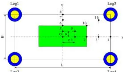
[image:3.612.191.401.479.603.2]The simulation parameters for leg hydraulic system are as follows: for a certain trailer concrete pump, weight is 6800kg, transverse span and longitudinal span of four legs are 2000mm and 4000mm respectively. The rotational speed of engine and pump is both 1450 rev/min, and the displacement of pump is 75cc/rev. The cylinder diameter, rod diameter and stroke of leg cylinders are 180mm, 125mm and 800m respectively. The position of the center of gravity of trailer concrete pump is shown in Figure 3. Where, y is the longitudinal coordinate axis, x is the transverse axis, O is the origin, c is the longitudinal eccentricity, e is transverse eccentricity.
Figure 3. The position of the center of gravity of trailer concrete pump.
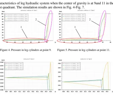
characteristics of leg hydraulic system when the center of gravity is at 9and 11 in the first quadrant. The simulation results are shown in Fig. 4-Fig. 7.
Figure 4. Pressure in leg cylinders at point 9. Figure 5. Pressure in leg cylinders at point 11.
Figure 6. Speed of piston rods at point 9. Figure 7. Speed of piston rods at point 11.
It can be seen that during the extending process, pressure in each cylinder is very low before 40 seconds. After 40 seconds pressure in each cylinder can be divided into two stages. Stage 1: Pressure rises slowly. Pressure in cylinder 3 is the biggest, Pressure in cylinders 1 and 4 are equal but lower than pressure in cylinder 3, while pressure in cylinder 2 is the smallest. With the center of gravity moves from 9 to 11, pressure in cylinder 3 increases accordingly. Stage 2: pressure in each cylinder rises sharply, and it will last about 0.8 second. In addition, velocity of cylinder 3 slows down at first, and then rises quickly. Velocity of cylinder 1, 2 and 4 rises slowly. Where, velocity of cylinder 2 is the fastest, velocity of cylinder 1 and 4 is lower than that of cylinder 2, and velocity of cylinder 3 is the slowest. With the center of gravity moves from point 9 to point 11, velocity of cylinder 3 is greatly affected.
CONCLUSIONS
According to the working principle of leg hydraulic system of trailer concrete pump, the simulation model of leg hydraulic system of trailer concrete pump is
1
2
1
[image:4.612.112.492.82.406.2]established based on AMESim, and the dynamic characteristics of leg hydraulic system of trailer concrete pump is analyzed. With the center of gravity moves towards one leg, the pressure in the corresponding leg will rise accordingly, and the extending speed of piston rod will decrease. The greater the center of gravity offset, the greater the influence of the dynamic characteristics of the leg cylinder. When using trailer concrete pump, in order to reduce the damage to leg cylinder, the center of gravity and the center of geometry should be coincident as much as possible.
ACKNOWLEDGEMENTS
This work was financially supported by the National Natural Science Foundation of China [grant number: 51365008]; the Joint Foundation of Science and Technology Department of Guizhou Province [grant number: Qiankehe LH Zi [2015]7658]; the Foundation of Science and Technology Department of Guizhou Province [grant number: Qiankehe J Zi [2010]2247]. The authors gratefully acknowledge their support. Additionally, Liu Huiyong acknowledges the financial support from China Scholarship Council (CSC) to visit the Fluid-Structure Interaction Research Group (FSIRG) in the Faculty of Engineering and the Environment at the University of Southampton [grant number 201606675008].
REFERENCES
1. Zhang Guozhong: Modern concrete pump truck and its application technology in construction
(China Building Materials Press, China 2004).
2. Chen Guoan, Zhu Zhencai, Li Siding: Maximum loading calculation for construction machinery
outriggers. Chinese Journal Of Construction Machinery, Vol.8(2) (2010), p. 162-165.
3. Tang Yongzhi, Que Shenghua: Optimal design of X-style supports’ angle of concrete pump
truck. Construction Mechanization, Vol.2 (2011), p. 47-48.
4. Zhang Yanwei, Sun Guozheng, Shi Laide: Counterforce Calculation and Structure Analysis
Method of Concrete Pump’s Stabilizers. Chinese Journal Of Construction Machinery, Vol.2(3) (2004), p. 253-258.
5. Kang Huimei: Analysis of concrete pump truck leg reaction force and the rising height.
Construction Machinery Technology & Management, Vol.4 (2002), p. 7-10.
6. Fu Yongling and Qi Xiaoye: System Modeling and Simulation Based on AMESim -- From