2017 3rd International Conference on Electronic Information Technology and Intellectualization (ICEITI 2017) ISBN: 978-1-60595-512-4
Research and Improvement of Test Case
Design Method for Program Logic
Cuiye Song and Xia Zheng
ABSTRACT
Test case design is an extremely important but very complicated task for dynamic test in white-box testing. In this paper, two commonly used methods, logical covering and basic path method are analyzed in detail, in order to show the deficiencies of them in high complexity, hard to use, and error prone. By combining the advantages of them, we make some improvement to the basic path testing, where independent paths are selected one by one, whose effectiveness is checked and conditions and data for the path is collected at the same time. An example is illustrated to show the feasibility and good traceability of the new design method for practical application.
INTRODUCTION
Software testing is an important way to guarantee the quality of the software, and it’s an activity through the whole life cycle of the software [1][2]. In the stage of implementation, coding, testing and debugging are the main activities to implement the software and make sure the program is correct as designed. Specifically, programmers should check the logic and the structure of the program, set check points, select special input data and run the program in order to observe whether the program act as desired. The most important and difficult thing is the selection of the input data and the derivation of the expected result, which we do in test case design according to the logical structure of the program.
_______________________
Logical coverage driven testing and basic path testing are the most commonly used methods for designing test case as illustrated in [3]. Usually, the fully covered test result is too complicated to get, thus the former becomes unfeasible for the programmers [4]. Basic path testing takes the control flow chart of the program as input as described in [3] and [5], but still hard to apply and error prone. Even though the path sets can be derived directly like in [6] and [7], the data in test case is hard to select. In this paper, i try to improve the basic path testing to make the test case design easier and clearer for the designer when they do the work manually. In this paper the cause of the complexity of logical covering testing is analyzed firstly, then the deficiencies in the basic path testing is described, finally the improvement is illustrated with an example to make the work more easier and traceable.
CAUSE OF THE COMPLEXITY IN LOGICAL COVERING
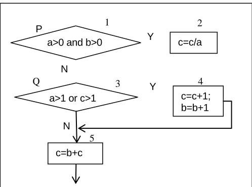
Logical covering provides quantified criteria for testers to select data for testing the program [3]. Figure 1 shows the flow chart of a simple code segment, where the
[image:2.612.162.411.406.591.2]input variable is a,b and c, and the cared output includes variables b and c. There are totally five nodes number from 1 to 5, two decision nodes named P and Q ,three statement blocks 2,4 and 5. There are totally four conditions in P and Q, they are a>0, b>0, a>1, c>1, numbered 1,2,3,4 respectively. T1,T2,T3,T4 represent that the conditions get true, and F1,F2,F3,F4 represent the false respectively.
Figure 1. A sample flow chart.
N N
Q
P
c=b+c
Y a>0 and b>0
a>1 or c>1 c=c+1; b=b+1 c=c/a Y
1 2
3 4
Complexity in Applying Steps
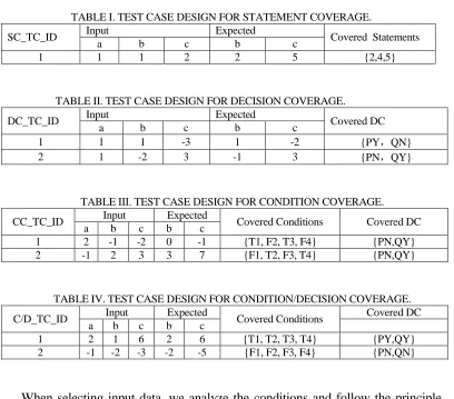
[image:3.612.98.506.141.500.2]Table I, Table II, Table III and Table IV show the test case design courses according to Figure 1 when applying the former four criteria in [3].
TABLE I. TEST CASE DESIGN FOR STATEMENT COVERAGE.
SC_TC_ID Input Expected Covered Statements
a b c b c
1 1 1 2 2 5 {2,4,5}
TABLE II. TEST CASE DESIGN FOR DECISION COVERAGE.
DC_TC_ID Input Expected Covered DC
a b c b c
1 1 1 -3 1 -2 {PY,QN}
2 1 -2 3 -1 3 {PN,QY}
TABLE III. TEST CASE DESIGN FOR CONDITION COVERAGE.
CC_TC_ID Input Expected Covered Conditions Covered DC a b c b c
1 2 -1 -2 0 -1 {T1, F2, T3, F4} {PN,QY} 2 -1 2 3 3 7 {F1, T2, F3, T4} {PN,QY}
TABLE IV. TEST CASE DESIGN FOR CONDITION/DECISION COVERAGE.
C/D_TC_ID Input Expected Covered Conditions Covered DC a b c b c
1 2 1 6 2 6 {T1, T2, T3, T4} {PY,QY} 2 -1 -2 -3 -2 -5 {F1, F2, F3, F4} {PN,QN}
Complexity in Multiple Conditions
The fundamental goal of software testing is to discover defects in the software. Among the six covering criteria, the former four, including statement coverage, decision coverage, condition coverage, condition/decision coverage, are easier to satisfy, but they leave out certain severe logical defects. Actually, if the logical operators in P and Q are not written properly, i.e., “&&” was written as “||”, or “||” as “&&”, the test cases in Table IV can not discover them. So multiple condition coverage is necessary.
TABLE V. COMPOSITIONS OF CONDITIONS.
TABLE VI. TEST CASE DESIGN FOR MULTIPLE CONDITION COVERAGE.
MC_TC_ID Input(a,b,c) Exp(b,c) Cov_C C_D C_Num 1 2,1,6 2,6 T1, T2,T3, T4 PY,QY 1,5 2 2,-1,-2 0,-1 T1, F2, T3, F4 PN,QY 2,6 3 -1,2,3 3,7 F1, T2,F3, T4 PN,QY 3,7 4 -1,-2,-3 -2,-5 F1, F2, F3, F4 PN,QN 4,8
As shown in Table V, when the multiple condition coverage is applied, all the possible logical composition of all the conditions in each decision node should be listed. All the conditions should be listed explicitly in case of being forgotten, which is still not enough for data choosing, because they scatter in different nodes in the graph, and the values may vary when the statements get executed.
Again, we run the algorithm in Figure 1 four times because we need four test cases, as shown in Table VI. The complexity grows linearly, and the criteria gets too complicated for practical application. Obviously we get that all the complexity grown from decision coverage to multiple condition coverage is caused by the operations of logical composition. If there is no logical “and” and “or”, the four criteria, including decision coverage, condition coverage, condition/decision coverage and multiple condition coverage, become one. Since the basic path testing decomposes all the logical composition, it’s more easier to apply.
DEFICIENCIES IN BASIC PATH TESTING
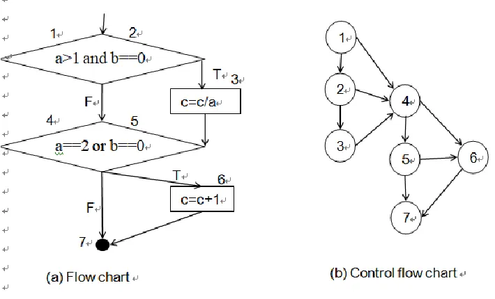
Basic path testing emphasizes the control flow chart, which derives from the
the Figure 1 and adjust the conditions and statements as Figure 2 (a) as in [3]. As shown in Figure 2 (b), the control flow chart, where only cycle with unique number and directed edge are reserved, is constructed according to the Figure 2 (a).
[image:5.612.118.473.246.461.2]Though the logical composition is decomposed, it actually covers the defects that the multiple condition coverage can discover, because at least one of the compositions 01 and 10 will be used to expose the logical error. But the deficiencies are 1) independent path is selected just according to the control flow chart which may introduce unreachable path; 2) data selection is still hard since we should calculate the actual branch of the decisions; 3) The test case only contains input data and expected result, thus it’s hard to trace the actual path and the changes of the variables, which is helpful to programmer to debug the program.
Figure 2. From flow chart to control flow chart.
IMPROVEMENT FOR APPLYING BASIC PATH TESTING
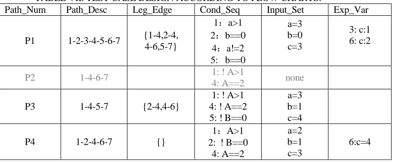
Some improvements are given for the test case derivation process is this section. As shown in Table VII, both the data selection and path checking are carried out according to a table with six columns, where Path_Num records the unique independent path, Path_Desc gives the complete path in the form of node sequence.
Step One: Choose a new independent path according to control flow chart in Figure 2 (b), analyze and record the conditions in each node in the Cond_Seq column;
[image:6.612.100.500.204.368.2]Step Two: If a set of input data can be found according to the condition set, record it in column Input_Set, and record the expected variation in each node in column Exp_Var where only the execution nodes are listed. Else if no input set exists, we discard the path as an unreachable path like P2 in gray.
TABLE VII. TEST CASE DESIGN ACCORDING TO FLOW CHARTS.
Path_Num Path_Desc Leg_Edge Cond_Seq Input_Set Exp_Var
P1 1-2-3-4-5-6-7 {1-4,2-4, 4-6,5-7}
1:a>1 2:b==0
4:a!=2 5: b==0
a=3 b=0 c=3
3: c:1 6: c:2
P2 1-4-6-7 1: ! A>1
4: A==2 none
P3 1-4-5-7 {2-4,4-6}
1: ! A>1 4: ! A==2 5: ! B==0
a=3 b=1 c=4
P4 1-2-4-6-7 {}
1:A>1 2: ! B==0
4: A==2
a=2 b=1 c=3
6:c=4
Step Three: For each effective path, we record the legacy edges that have not been covered yet in the column Leg_Edge.
Step Four: If there are still edges uncovered yet, go to Step One, else if the new Leg_Edge value becomes empty, finish the work.
Compared with the original basic path testing, the improvement brings high traceability and less error prone because of the sufficient information. And what’s more, unreachable path can be discarded directly during the design process.
CONCLUSIONS
REFERENCES
1. Zhitao He, Chao Liu and Haihua Yan. 2015.”Software testing evolution process model and growth of software testing quality” in Science China(Information Sciences). 58(3):1-6.
2. GJ Myers. The Art of Software Testing, Second Edition. Wiley, 2004 , 17 (2) :174-179. 3. Fasheng Wang, Xucheng Li, 2016, Practical software testing course.41-52. In Chinese.
4. Jun-wei DuWen-wen Yin. “A Test Case Generation Method for Specific Path Coverage Oriented” in the World Conference on Control, Electronics and Electrical Engineering, 2015-1-17.
5. McCABE T J. 1976.”A complexity measure” inIEEE Transactions on Software Engineering, SE-2(4): 308-320.
6. Min Yu, Shaomin Chen, Yaguang Chen. 2013, “Test case design algorithm for basic path test” in
Journal of Computer Applications, 33(11): 3262-3266.